
International Journal of Scientific & Engineering Research, Volume 4, Issue 12, December-2013 314
ISSN 2229-5518
Design and Analysis of Automatic Fuse Circuit
Model Based on Simulation
C.Maruthi Ratna Kishore,
Electrical Engineering.Dept, Rise group of Institutions,
Ongole-523001, AndhraPradesh, India.
Abstract— This paper deals with a newly proposed fuse circuit namely “Automatic Fuse Circuit” and its working is mainly based on thermal property of current carrying conductor. This may be a better electrical fuse circuit than the rewirable, resettable fuses which are used in domestic and industrial loads at present. The fuse circuit model is built in National Instruments Multisim 11.0 software and the parameters of the fuse circuit are as user interface. Also this paper indicates several advantages of the automatic fuse and compared with that of the rewirable fuses used mainly in domestic and industrial loads.
Index Terms— Automatic fuse, Electrical-circuit fuse, resettable fuse, rewirable fuse, thermal based fuse, temperature sensor, simulation, comparator.
HE use of rewirable and resettable electrical fuses occupies highly significant place in providing protection
from over load current both in domestic as well as in
The design and working of automatic fuse mainly depends on temperature of the supply in the conductor. At the time of fault, large Amperes of current or overload current is drawn
IJSER
industrial sectors at present. But a notable disadvantage of
these fuses is that,passing overload currents through fuse element causes heat and open the current path[1]. So when such fault occurs, supply will be cut off and the supply will be restored when fuse is rewired manually. Till the supply is restored every activity to be done by electricity will be held up. To clear fault currents in such fuses, improvements are made with all the required considerations using elements such as aluminum, cadmium and bounded silica sand, etc, in the construction of fuse. [2], [3], [4].
In spite of the improvements made for the effective
working of fuses, the fault in fuses continues. To come over this problem, sincere efforts are put forward and an automatically working circuit is developed in this paper. Its working is based on different temperature levels of conductors used in the supply with regarding to various current ratings, cross-sectional areas. The procedure is useful to put an end to the discontinuity gap where fault occurs. So it is evident that the fuse serves two purposes- it restores electricity when fault occurs and also works as safety measure in providing protection from overloads and such protection depends on the selection of fuse criteria. [5]. Also the available protection depends on different types of fuse construction in various electrical circuits. [6].The proposed automatic fuse construction stands good both for safety and accurate
functioning.
by loads and the low resistance wire inside fuse gets melted due to high temperature current flows through it and isolate faulted equipment from the network [7].The characteristics of different size copper external and internal conductors with different currents carrying through them produce various temperatures, with X-(cross-sectional area in square. Millimeter), Y-(current in amperes), Z-(temperature in degrees centigrade) axis, shown in fig (1), fig (2). From this analysis, the temperature of a normal current in domestic load can be estimated.
Automatic fuse system mainly consists of a temperature
sensor LM135, OP-AMP 741 as a comparator, and a relay of solenoid type with contact of require supply rating to close or open the connection. The temperature sensor (Voltage dependent voltage source V2 in simulation circuit) sense the temperature of the supply wire and it should be kept in a closed box to avoid error from atmosphere temperature. The closed box contains a copper metal strip of having same capacity that of supply conductor, the passing of electrical current in the copper strip introduces electrical-thermal- mechanical interactions in which temperature sense by LM135, [8], [9].
IJSER © 2013 http://www.ijser.org
International Journal of Scientific & Engineering Research, Volume 4, Issue 12, December-2013 315
ISSN 2229-5518
700
600
500
400
300
200
100
0
1 3 5 7 9 11 13 15 17 19
cross-section area(sq.mm)
Current(Amp' s)
Temperature(
celsius)
The designed and tested circuit by using Multisim/Simulation with user interface parameters is shown in fig(3)&fig(4),and the DC transfer characteristics of the designed circuit also shown in fig(5).From the fig’s3,4 the accuracy of temperature sensor LM135 is clearly visible. The components of circuit work more accurately and effectively even in case of small change in current is shown by DC transfer characteristics of
the circuit. The open and close of the circuit depends on the
Fig.1. Different sizes of external copper conductor temperatures with
different currents.
reference value of input to the comparator.
700
600
500
400
300
200
100
0
cross-section area(sq.mm)
current(Amp's)
Temperature(cel sius)
1 3 5 7 9 11 13 15 17 19 21

Fig.2.Different sizes internal of copper-conductor temperatures with different currents.
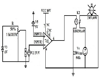
The LM135 works with +5V and sense temperature in terms of 100milliVolts/1degreeCelsius, output is connected to comparator as a second input. The first input of comparator is fixed to a certain value (V5) greater than the second input, then inside the comparator if Input2 < Input1 takes place then the pin. No 7(VCC) is highlighted. The output value resulted is equal to the value of Vcc, which is equal to the relay input value. By giving the input to the relay, it closes the two wires of supply, one from supply and other from the load, and then the load gets electricity. In the other condition where Input2 > Input1, the pin. NO 4 is highlighted, and it must be connected to ground to get no output, then relay opens the connection between supply and load. Thus the open and close action of automatic fuse circuit happens. The total circuit will work by DC supply which is provided by an AC-DC converter circuit of +5v and also by voltage regulator IC’s. The whole circuit can be arranged in a compactable size due to electronic
components utilization.
Fig.3. Input2 < Input1 condition, the relay is closed and load gets power.
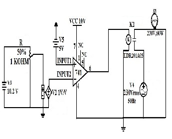
Fig.4. Input2 > Input1 condition, the relay is opened and load doesn’t get power.
IJSER © 2013 http://www.ijser.org
International Journal of Scientific & Engineering Research, Volume 4, Issue 12, December-2013 316
ISSN 2229-5518
[5] Huang, R.K.; Nilsson, S. "Fuse selection criteria for safety applications “Product Compliance Engineering (ISPCE), 2012 IEEE Symposium, pp.1-8.
[6] Wright, A.; Nottingham Univ., UK, "Construction, behaviour and application of electric fuses ", IEEE Power Engineering Journal (Volume: 4, Issue: 3, 1990 )pp.141 – 148.
[7] WrightA, and Newbery PG(2004). "Electric Fuses", Chapter3, London: IEE.
[8] Zhao, Guangfeng ; Liu, Ming ; An, Zhinan ; Ren, Yang ;Liaw, Peter K.
; Yang, Fuqian , "Electromechanical responses of Cu strips",IEEE Journal of Applied Physics (Volume: 113 , Issue: 18, 2013).pp.183521 -
183521-10.
[9] Gomez,J.C.;Campetelli,N.G.;Reineri,C.A.,"Cablesandconductorsprote ction,partI:cables",LatinAmericaTransactions,IEEE(RevistaIEEEAmer icaLatina),Volume:11, Issue:1,2013,pp. 426 – 431.
Fig.5.DC Transfer Characteristics of OP-AMP circuit.
In the automatic fuse, closing and opening of the circuit is highly accurate. The size of the circuit will be small and compact. The system works automatically. Hence no need of rewiring manually. The automatic fuse is economical since available for low cost and risk less.
In the light of the working of the automatic fuse and its advantages, it can be concluded that the automatic fuse is a better one than the rewirable, resettable and reclose fuses.
[1] Farahani, H.F.; Asadi, M.; Kazemi, A., "Analysis of thermal behavior of power system fuse using finite element method ",IEEE Power Engineering and Optimization Conference (PEOCO), 2010 4th International, (June 2010),.pp. 189 – 195.
[2] Westrom A, Crooks W R et al. (1981). "Current limiting fuses – a comparative evaluation", 9th IEEE Power Engineering Society, vol PER-2(7), 25–26.
[3] Leach J G (1985). "New application flexibility for medium–voltage current–limiting fuses ", IEEE Transaction on Industry Applications, vol IA21 (4), 1075–1080.
[4] Narancic V, Braunovic M et al. (1979). “The composite fuse – a new technology for current limiting fuses", 7th IEEE Power Engineering Society Transmission and Distribution Conference and Exposition,
462–470.
IJSER © 2013 http://www.ijser.org
International Journal of Scientific & Engineering Research, Volume 4, Issue 12, December-2013
ISSN 2229-5518
317
IJSER 2013 http://www 11ser.org