International Journal of Scientific & Engineering Research, Volume 6, Issue 2, February-2015 9
ISSN 2229-5518
Design And Simulation Of Binary Floating Point
Multiplier Using VHDL
Miss. U. V. Chaudhari Prof. A. P. Dhande
Abstract -Most of the DSP applications need floating point numbers multiplication. The possible ways to represent real numbers in binary format floating point numbers are; the IEEE 754 standard represents two floating point formats, Binary interchange format and Decimal interchange format. To improve speed multiplication of mantissa is done using specific multiplier replacing Carry Save Multiplier. To give more precision, rounding is not implemented for mantissa multiplication. The binary floating point multiplier is plane to do implemented using VHDL and it is simulated and synthesized by using Modalism and Xilinx ISE software respectively. The result so got will be compare with the previous work done.Floating point multiplication is important in many commercial applications including financial analysis, banking, tax calculation, currency conversion, insurance, and accounting.
Keywords -floating point, Modalism, Xilinx ISE, Binary interchange format, Decimal interchange format.
—————————— ——————————
1 INTRODUCTION
Floating point numbers are one possible way of represent- ing real numbers in binary format, the IEEE 754[1] standard presents two different floating point formats, Binary inter- change format and Decimal interchange format. Multiplying floating point numbers is a critical requirement for DSP appli- cations involving large dynamic range. This paper focuses only on single precision normalized binary interchange for- mat. It consists of a one bit sign (S), an eight bit exponent (E), and a twenty three bit fraction (M or Mantissa). An extra bit is added to the fraction to form what is called the significant. If the exponent is greater than 0 and smaller than 255, and there is 1 in the MSB of the significant then the number is said to be a normalized number. Multiplying two numbers in floating point format is done by adding the exponent of the two num- bers then subtracting the bias from their result,and multiply- ing the significant of the two numbers, and calculating the sign by XORing the sign of
the two numbers. The multiplier was verified against Xilinx floating point multiplier. In this seminarrepresentation of floating point multiplier in such a way that rounding support isn’t implemented, thus accommodating more precision if the multiplier is connected directly to an adder in a MAC unit. Exponents addition, Significant multiplication, and Results sign calculation are independent and are done in paral- lel.Xilinx ISE Design Suite 13.3 tool & VHDL programming is used. ISIM tool is used for Simulation process .Xilinx core generator tool is used to generate Xilinx floating point multi- plier core The whole multiplier (top unit) was simulated against the Xilinx floating point multiplier core generated by Xilinx core generator.
A Binary multiplier is an integral part of the arithme- tic logic unit (ALU) subsystem found in many processors. In- teger multiplication can be inefficient and costly, in time and hardware, depending on the representation of signed num- bers. Both's algorithm and others like Wallace-Tree suggest techniques for multiplying signed numbers that works equally well for both negative and positive multipliers. In this project, we have used VHDL as a HDL and Mentor Graphics Tools (MODEL-SIM & Leonardo Spectrum) for describing and veri-
fying a hardware design based on Both's and some other effi- cient algorithms. Timing and correctness properties were veri- fied. Instead of writing Test- Benches & Test-Cases we used Wave-Form Analyzer which can give a better understanding of Signals &variables and also proved a good choice for simu- lation of design. Hardware Implementations and synthesiza- bility has been checked by LeonardoSpectrum and Precision Synthesis.
2. ANALYSIS OF PROBLEM
2.1Floating Point Multiplication Algorithm
The normalized floating point numbers are of the form shown in
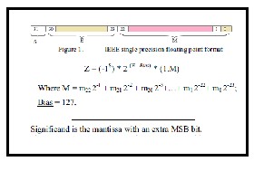
Figure 1: IEEE single precision floating point format
Floating point multiplication can be done by multi- plying the significant of two floating point numbers and add- ing the exponents,then subtract the Bias from added exponent result (E1 + E2 – Bias).Sign is obtained by xor-ing the MSB of two numbers,then normalize the result.Rounding of result is done to fit in the available bits and if desired finallycheck the underflow/overflow occurrence.The bias constant used is (127
= 001111111).
IJSER © 2015 http://www.ijser.org
International Journal of Scientific & Engineering Research, Volume 6, Issue 2, February-2015 10
ISSN 2229-5518
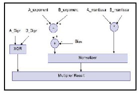
Figure 2: Block diagram of floating point multiplier
2.2 Design Of Floating Point Multiplier
2.2.1 SIGN BIT CALCULATION
Multiplying two numbers result is a negative sign if one of the multiplied numbers is of a negative value. By the aid of a truth table we find that this can be obtained by XORing the sign of two inputs.
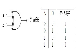
Figure 3: Sign bit calculator-XOR gate
2.2.2 UNSIGNED ADDER (FOR EXPONENT ADDITION)
This unsigned adder is responsible for adding the exponent of the first input to the exponent of the second input and after that subtract the Bias (127) from the addition result (i.e. A_exponent + B_exponent - Bias). The result of this stage is called the intermediate exponent. The addition operation is done on 8 bits, and there is no need for a quick result because most of the calculation time is spent in the significand multi- plication process (multiplying 24 bits by 24 bits); thus we need a moderate exponent adder and a fast significand multipli- er.An 8-bit ripple carry adder is used to add the two input exponents. A ripple carry adder is a chain of cascaded full ad- ders and one half adder; each full adder has three inputs (A, B, Ci) and two outputs (S, Co). The carry out(Co) of each adder is fed to the next full adder (i.e each carrybit "ripples" to the next full adder).The addition process produces an 8 bit sum (S7 to
S0) and a carry bit (Co,7). These bits are concatenated to form a 9 bit addition result (S8 to S0) from which the Bias is sub- tracted. The Bias is subtracted using an array of ripple borrow subtractors. The addition process produces an 8 bit sum (S7 to S0) and a carry bit (Co,7). These bits are concatenated to form a 9 bit addition result (S8 to S0) from which the Bias is sub- tracted. The Bias is subtracted using an array of ripple borrow subtractors.
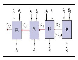
Figure 4:Unsigned Adder
2.2.3 BIAS SUBTRACTION
Subtract the bias constant (127 = 001111111) from un- signed exponent adder result for this, two zero substractors (ZS) and seven one subtractors (OS) are used . S0…..S8 is the unsigned adder result (9 bit ) .T=001111111 is the Bias con- stant. Bias subtractor result is R =S-T.
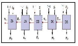
Figure 5: Bias Subtractor
2.2.4 UNSIGNED MULTIPLIER (FOR SIGNIFICAND MULTIPLICATION)
This unit is responsible for multiplying the unsigned significand and placing the decimal point in the multiplication product. The result of significand multiplication will be called the intermediate product (IP). The unsigned significand mul- tiplication is done on 24 bit. Multiplier performance should be taken into consideration so as not to affect the whole multipli- ers performance. A 24x24 bit carry save multiplier architecture
is used as it has a moderate speed with a simple architecture.
IJSER © 2015 http://www.ijser.org
International Journal of Scientific & Engineering Research, Volume 6, Issue 2, February-2015 11
ISSN 2229-5518
In the carry save multiplier, the carry bits are passed diagonal- ly downwards (i.e. the carry bit is propagated to the next stage). Partial products are made by ANDing the inputs to- gether and passing them to the appropriate adder.This is done in significand multiplication process which is one of the im- portant steps in floating point multiplication
2.2.5 NORMALIZER
The result of the significand multiplication (interme-
diate product) must be normalized to have a leading 1 just to
the left of the decimal point (i.e. in the bit 46 in the intermedi-
ate product). Since the inputs are normalized numbers then
the intermediate product has the leading one at bit 46 or 47. If
the leading one is at bit 46 (i.e. to the left of the decimal point)
then the intermediate product is already a normalized number
and no shift is needed. If the leading one is at bit 47 then the
intermediate product is shifted to the right and the exponent is
incremented by 1.
2.2.6 OVERFLOW/UNDERFLOW DETECTION
Overflow/underflow means that the results exponent
is too large/small to be represented in the exponent field. The
exponent of the result must be 8 bits in size, and must be be-
tween 1 and 254 otherwise the value is not a normalized one
.An overflow may occur while adding the two exponents or
during normalization. Overflow due to exponent addition
maybe compensated during subtraction of the bias; resulting
in a normal output value (normal operation). An underflow
may occur while subtracting the bias to form the intermediate
exponent. If the intermediate exponent < 0 then its an under-
flow that can never be compensated; if the intermediate expo-
nent = 0 then its an underflow that may be compensated dur-
ing normalization by adding 1 to it .When an overflow occurs
an overflow flag signal goes high and the result turns to
±Infinity (sign determined according to the sign of the floating
point multiplier inputs). When an underflow occurs an under-
flow flag signal goes high and the result turns to ±Zero (sign
determined according to the sign of the floating point multi-
plier inputs). Denormalized numbers are signaled to zero with
the appropriate sign calculated from the inputs and an under-
flow flag is raised.
3. OBJECTIVES
Although computer arithmetic is sometimes viewed as a specialized part of CPUdesign, still the discrete compo- nent designing is also a very important aspect. Atremendous variety of algorithms have been proposed for use in floating- point systems.Actual implementations are usually based on refinements and variations of the few basicalgorithms present- ed here. In addition to choosing algorithms for addition, sub- traction,multiplication, and division, the computer architect must make other choices. Whatprecisions should be imple- mented? How should exceptions be handled? This report willgive the background for making these and other decisions.
3.1 VHDL
The VHSIC (very high speed integrated circuits) Hardware Description Language(VHDL) was first proposed in
1981. The development of VHDL was originated by IBM,Texas Instruments, and Inter-metrics in 1983. The result, contributed by manyparticipating EDA (Electronics Design Automation) groups, was adopted as the IEEE1076 standard in December
1987.VHDL is intended to provide a tool that can be used by the digital systemscommunity to distribute their designs in a standard format. Using VHDL, they are able totalk to each other about their complex digital circuits in a common lan- guage withoutdifficulties of revealing technical details.As a standard description of digital systems, VHDL is used as input and output tovarious simulation, synthesis, and layout tools. The language provides the ability todescribe systems, net- works, and components at a very high behavioral level as well asvery low gate level. It also represents a top-down methodol- ogy and environment. Simulations can be carried out at any level from a generally functional analysis to a verydetailed gate-level wave form analysis.
3.2 Floating Point Arithmetic
Many applications require numbers that aren’t inte-
gers. There are a number ofways that non-integers can be rep-
resented. Adding two such numbers can be done withan inte-
ger add, whereas multiplication requires some extra shifting.
There are variousway to represent the number systems. How-
ever, only one non-integer representation hasgained wide-
spread use, and that is floating point.
4. OUTCOME
The result of the significand multiplication (interme- diate product) must be normalized to have a leading „1‟ just to the left of the decimal point (i.e. in the bit 46 in the interme- diate product). Since the inputs are normalized numbers then the intermediate product has the leading one at bit 46 or 47. If the leading one is at bit 46 (i.e. to the left of the decimal point) then the intermediate product is already a normalized number and no shift is needed. If the leading one is at bit 47 then the intermediate product is shifted to the right and the exponent is incremented by 1.
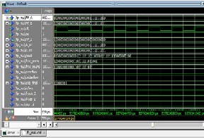
Figure 6: Input and output waveform
IJSER © 2015 http://www.ijser.org
International Journal of Scientific & Engineering Research, Volume 6, Issue 2, February-2015 12
ISSN 2229-5518
5. RESULT ANALYSIS
The design has been implemented and simulated by
using ModelSim. Consider inputs to the floating point multi-
plier are:
A = 00111111110000000000000000000000
B = 11111111100000000000000000000001
The output of the multiplier should be
010000000000001011111101100001111111010000000100
Flag outputs of this multiplier are Overflow = 0; underflow =
1; final exponent = 10000001; zero = 0
This presents design and simulation of a floating
point multiplier that supports the IEEE 754-2008 binary inter-
change format, the proposed multiplier doesn’t implement
rounding and presents the significand multiplication result as
is (48 bits), this gives better precision if the whole 48 bits are
utilized in another unit; i.e.with a floating point adder to form
a MAC unit. But the floating point multiplier core generated
by Xilinx core generator does not indicates the entire 48 bits of
mantissa due to rounding and is not beneficial in case of DSP
application of large dynamic range especially when using it in
another high precision floating point units like Multiply and
Accumulate (MAC) unit.
6. REFERENCES
1.Remadevi R / International Journal of Engineering Research
and Applications (IJERA) ISSN: 2248-9622 www.ijera.com Vol.
3, Issue 2, March -April 2013, pp.283-286 283 “Design and
Simulation of Floating Point Multiplier Based on VHDL” .
2.International Journal of Engineering Research and Develop- ment e-ISSN: 2278-067X, p-ISSN: 2278-800X, www.ijerd.com Volume 10, Issue 3 (March 2014), PP.73-78 73 “Design of Float- ing Point Multiplier Using Vhdl” P.Gayatri(Department of Electronics & Communication Engineering, Lendi Institute of Engineering and Technology/JNTUK, India).
3.L. Louca, T. A. Cook, and W. H. Johnson, “Implementation of IEEESingle Precision Floating Point Addition and Multiplica- tion on FPGAs,”Proceedings of 83 the IEEE Symposium on FPGAs for CustomComputing Machines (FCCM’96), pp. 107–
116, 1996.
4.A. Jaenicke and W. Luk, "Parameterized Floating-Point
Arithmetic on FPGAs", Proc. of IEEE ICASSP, 2001, vol. 2,
pp.897-900.
5.B. Lee and N. Burgess, “Parameterisable Floating-point Op-
erations on FPGA,” Conference Record of the Thirty-Sixth Asi-
lomar Conference onSignals, Systems, and Computers, 2002.
6.Mohamed Al-Ashrafy, Ashraf Salem and WagdyAnis” An
Efficient Implementation of Floating PointMultiplier” Elec-
tronics, Communications and Photonics Conference (SIECPC),
2011 Saudi International.
IJSER © 2015 http://www.ijser.org