The block diagram and front panel of pressure
measurement VI is shown in figure 1.1 & 1.2
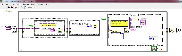
Fig. 1.1 Block diagram of pressure measurement VI
International Journal of Scientific & Engineering Research, Volume 3, Issue 11, November-2012 1
ISSN 2229-5518
DEVELOPMENT OF LABVIEW BASED WIRELESS CONTROL SYSTEMS FOR ION BEAM MICROMACHINING SYSTEMS
Abstract- Ion beams are becoming increasingly important in miniaturization of semiconductor devices. When ion beam is focused to micron / submicron spot size, several processes takes place on the substrate at the same time. Ion beam interaction with the surface produces various phenomena such as sputtering of substrate material, ion implantation, secondary electron emission etc. Sputtering mechanism is the most important one in the field of micromachining applications. Few months ago plasma based focused ion beam system has been developed in Variable Energy Cyclotron Centre, kolkata for high speed micromachining applications which has immense application in Material science, MEMS etc. Previously the entire system was controlled using conventional control system (using cables).The aim of the project was to eliminate the cables by utilizing wireless communication to enhance the performance of the system and develop few applications to automate the operation.
All the work is carried out in the Dept. of Atomic energy/VECC/Kolkata.
The key parts in this paper are LabVIEW, Xbee and RS-232.The parameters which are controlled are vacuum dual gauge , RF power generator, KE 6487 picoammeter. The following part gives the brief introduction of the LabVIEW and Xbee.
In LabVIEW, you build a user interface with a set of tools and objects. The user interface is known as the front panel. You then add code using graphical representations of functions to control the front panel objects. The block diagram contains this code. In some ways, the block diagram resembles a flowchart.
LabVIEW programs are called virtual instruments, or VIs, because their appearance and
operation imitate physical instruments, such as
IJSER © 2012 http://www.ijser.org
International Journal of Scientific & Engineering Research, Volume 3, Issue 11, November-2012 2
ISSN 2229-5518
oscilloscopes and multimeters. Every VI uses functions that manipulate input from the user interface or other sources and display that information or move it to other files or other computers.
A VI contains the following three components: Front panel—Serves as the user interface. Block diagram—contains the graphical source code that defines the functionality of the VI.
to a subroutine in text-based programming languages.
International is a wireless transceiver. The XBee uses a fully implemented protocol for data
communications that provides features needed for robust network communications in a wireless sensor network (WSN). Features such as addressing, acknowledgements and retries help ensure safe delivery of data to the intended node. The XBee
also has additional features beyond data communications for use in monitoring and control of remote devices.
The TPG 262 is used together with Pfeiffer vacuum compact gauges for total pressure measurement. By using the block diagram and front panel of pressure measurement VI we can very easily understood how to measure the pressure in the vacuum chamber.
The block diagram and front panel of pressure
measurement VI is shown in figure 1.1 & 1.2
Fig. 1.1 Block diagram of pressure measurement VI
IJSER © 2012 http://www.ijser.org
International Journal of Scientific & Engineering Research, Volume 3, Issue 11, November-2012 3
ISSN 2229-5518
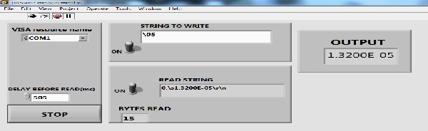
Fig. 1.2 Front panel of pressure measurement VI
The code for the pressure measurement VI is shown in block diagram and the required output is shown
in the front panel.
Power is generated using the RF power generator. Using the set point VI we can control the input power given to the ion beam micromachining systems. Set point VI front panel & block diagram is shown in figure 1.3 & 1.4
The code for the set point VI is shown in the block diagram. We can see that after writing the hex string to set the input power level as 100w we got the required response which is indicated in the read buffer. The power indicator shows the input power reading .
The KE 6487 picoammeter is used for the ion beam current measurement. The block diagram & front panel of the current measurement VI is shown in
figure 1.5 & 1.6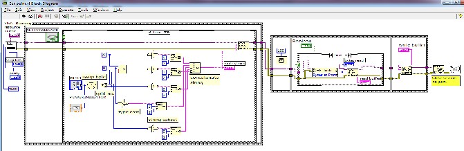
Fig. 1.3 Block diagram of set point VI
IJSER © 2012 http://www.ijser.org
International Journal of Scientific & Engineering Research, Volume 3, Issue 11, November-2012 4
ISSN 2229-5518
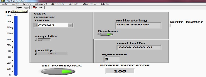
Fig. 1.4 Front panel of Set point VI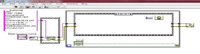
Fig.1.5 Block diagram of current measurement VI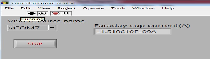
Fig.1.6 Front panel of current measurement VI
IJSER © 2012 http://www.ijser.org
International Journal of Scientific & Engineering Research, Volume 3, Issue 11, November-2012 5
ISSN 2229-5518
The KE 6487 picoammeter supports to send number of commands at a time as shown in block diagram. The front panel shows the current measurement reading.
All the experimental results are shown in the previous part. The results shows that the use of LabVIEW , Xbee and RS-232 have effectively being applied for wireless controlling of vacuum dual gauge, RF power generator and KE 6487 picoammeter. We can use this system for controlling any type of serial instrument if its
having the data rate supported by Xbee wireless module.
The performance & efficiency of this system having advantages over the conventional wired system. We can control the system remotely by limiting the complexity and increasing the suitability of the system.
1. www.ni.com
2. www.digi.com
3. Larsen LabVIEW for engineers
4. LABVIEW - PRACTICAL APPLICATIONS AND SOLUTIONS Edited by Silviu Folea
IJSER © 2012 http://www.ijser.org