International Journal of Scientific & Engineering Research, Volume 5, Issue 1, January-2014 1874
ISSN 2229-5518
DESIGNING OF THE CONICAL CORRUGATED HORN ANTENNA
Divya Gupta
Abstract— The objective of the paper is to provide the overview of the principle of operation and designing approach that is used to design the conical corrugated horn antenna. This paper deals with the designing of the conical corrugated horn with large aperture and narrow flare angle of 15 degree using brass plates that would produce symmetric radiation patterns, good impedance match and low crosspolarisation which would be used as feed horn for the Cassegrain antenna working at 35.6 GHz for cloud radar. The final design using High Frequency Simulator System (HFSS), shows successful simulated results with symmetrical E and H radiation patterns with good impedance match and low cross polar levels.
Index Terms— Corrugated horn, Conical corrugated horn, Feed horn
1 INTRODUCTION
—————————— ——————————
properties such as symmetrical radiation pattern, low sidelobes, low crosspolarisation and a resulting good
THERE are three main reasons for the existence of
corrugated horn antennas. Firstly, they exhibit radiation pattern symmetry, which offers the potential for
producing reflector antennas with high gain and low
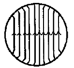
return loss. In order to obtain these properties, in particular the symmetrical radiation pattern and low crosspolar level, the aperture field must be almost linear as shown in figure 1 below.
spillover; secondly, they radiate with very low crosspolarisation, which is essential in dual polarisation systems and finally, they offer a wide bandwidth response.
Now-a-days, in the age of the communications, horn antennas take a very important role in the development of the actual and future communications systems with
high requirements in their radiations patterns. In fact,
corrugated feeds are the best feeds ever developed.
Ten to twenty years ago, corrugated horn antennas were restricted to be used in high performance applications, like being on board of satellites, earth station radio telescope horns, antenna measurement chambers and very few more applications. They were restricted to those applications for two main reasons: difficulties in the design and difficulties in the manufacture process of a corrugated feed.
Now-a-days, likely global market applications for
corrugated feeds are: compact parabola feeds, covert surveillance, secure communications, base station power saving, reduced interference.
Fig 1. Ideal aperture electric field in corrugated horn
Looking at figure 1, a small amount of field curvature is present and the fields are not precisely linear. This particular aperture electric field is required to cancel all the crosspolar components, thus yielding very low crosspolarisation. By examining the aperture fields of an
'open-ended corrugated waveguide, the dominant mode


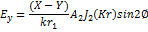
in a hybrid mode waveguide that produces the aperture electric fields is [1]
(1)
2 PRINCIPLES OF OPERATION OF CORRUGATED HORN
The corrugated wall that alters the field pattern in a
corrugated waveguide describes the principle of operation of corrugated horns. The corrugations of the walls will change the fields to achieve desirable
IJSER © 2014 http://www.ijser.org
International Journal of Scientific & Engineering Research, Volume 5, Issue 1, January-2014 1875
ISSN 2229-5518

Where  and are amplitude coefficients,
  and are the Bessels function of the first kind . K and k are the transverse and the free-space wavenumbers and X and Y are the impedance and the admittance at the boundary r

= r1 given by
waveguide and the mode converter, and a
corrugated transition section between the mode converter and the output flare. The transition section accommodates any necessary changes in flare angle, slot depth, and pitch between the mode converter and output flare. Slot widths are varied between 0.1λ and 0.3λ. Ridge width to
slot width ratios are taken between 0.1 to 1[3].


And is the admittance of free space.
(2)

4 DESIGN STEPS
4.1 Choosing the waveguide feed Normally, conical corrugated horn is fed from a smooth-wall circular waveguide supporting the

fundamental mode. A circular waveguide of
diameter 6.35 mm is selected circular waveguide
From equation 1, no crosspolarised field exists
when the term (X-Y) vanishes. This is because the angular variable ɸ will not affect the aperture field with Ey = 0. For (X - Y) term to approach zero, both X and Y will have the same value. Due to the corrugations, both X and Y value will be
zero. With these properties, the electric and
standards, whose operating band is 33.0 – 38.5
GHz as we are working for Ka band and our operating frequency is 35.6GHz and mode cutoff frequency is 27.27 GHz for  mode.
mode.
4.2 Dimensions of the corrugated
IJSER
magnetic fields are exactly balanced to produce
radiation pattern symmetrical copolar patterns
and low crosspolarisation. This is described as a

'balanced hybrid' mode. Low crosspolarisation
can be achieved by designing the corrugation geometry in such a way that no current flows axially along the corrugated ridges. With quarter of wavelength deep corrugations, the corrugations will behave as short transmission lines. This is to ensure that the axial current will not flow. This condition is based on assuming that the corrugated wall is a flat plane surface.
3 DESIGN METHODOLOGY
For most applications the horn is fed from a smooth-wall circular waveguide supporting the fundamental  mode. We therefore require a mode converter, which transforms the
  to the
  mode. This conversion must be carried out with negligible mismatch and excitation of higher order modes, particularly the highly cross- polarized
  slow (surface) wave and the

mode.
For optimum performance it is essential to optimize the parameters of the mode converter independently of the input waveguide diameter and the horn output flare. Two additional sections are therefore required to complete the horn; an input taper between the input
horn
Usually, for a normal corrugated horn antenna, the input mode at the throat region will be the smooth circular waveguide mode; this
mode defines approximately the input radius of
the corrugated horn antenna profile. For minimum return loss of this mode, corrugation depth at the throat region must be around λ/2.
So, the corrugated horn antenna is designed
using HFSS(High Frequency Structure Simulation)with slot width s=1mm,ridgewidth w=0.5mm as width-to-pitch ratio δ is usually taken to be 0.7≤ δ≤ 0.9 [2] and the pitch p,is usually chosen to be such that  ≤ p≤
≤ p≤ . [4].
For 1 ≤ j ≤  +1, then the slot depth of the jth
slot is
 (3) where σ (0.4 ≤ σ ≤ 0.5) is a percentage factor for the first slot depth of the mode converter.
 is the number of slots in the mode converter.
5 RESULTS
All simulated results are obtained using
HFSS(High Frequency Simulator System).
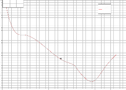
Figure 2, shows the return loss plot of the
designed conical corrugated horn antenna. And
IJSER © 2014 http://www.ijser.org
International Journal of Scientific & Engineering Research, Volume 5, Issue 1, January-2014 1876
ISSN 2229-5518
for a chosen operating frequency of 35.6GHz the return loss is -23.606GHz. The return loss measured from the corrugated horn exhibits an excellent impedance match at the throat region of the horn with a design operating frequency of
35.6GHz
22.50
20.00
17.50
15.00
12.50
Name X Y
m1 0.0000 20.1416
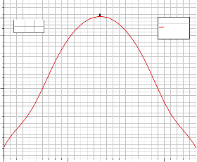
XY Plot 15
m1

HFSSDesign1 ANSOFT
Curve Info dB(GainTotal)
Setup1 : LastAdaptive
Freq='35.6GHz' Phi='90deg'
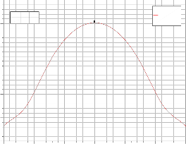
Figure 3a and figure 3b shows the rectangular plot of the E and H plane of the radiation pattern respectively. From fig. 3a and fig. 3b, the obtained gain of the designed conical corrugated horn antenna is 20.1416dB.This figure shows the copolar plot of the radiation pattern
10.00
7.50
5.00
2.50
0.00
-30.00 -20.00 -10.00 0.00 10.00 20.00 30.00
Theta [deg]
Figure 4 shows the copolar and crosspolar level
Fig 3b Rectangular Plot of H Plane Radiation Pattern
XY Plot 3

HFSSDesign1 ANSOFT
of the designed conical corrugated horn antenna. From Fig4, at boresight, gain (copolar) in dB is
20.1416dB and the cross-polarization to this in dB
is -39.5512 dB. So, the
cross-polarization level at boresight is -
59.6922dB.
25.00
0.00
-25.00
Name X Y
m1 0.0000 20.1416 m2 0.0000 -39.5512
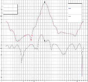
m1
Curve Info dB(GainPhi)
Setup1 : LastAdaptive
Freq='35.6GHz' Phi='0deg'
dB(GainTheta) Setup1 : LastAdaptive Freq='35.6GHz' Phi='0deg'
IJSERm2
0.00
-5.00
Name X Y
m1 35.6000 -23.6067
XY Plot 1
Curve Info dB(S(1,1))
Setup1 : Sw eep

HFSSDesign1 ANSOFT
-50.00
-10.00
-75.00
-15.00
-20.00
-25.00
-30.00
-35.00
m1
28.00 30.00 32.00 34.00 36.00 38.00 40.00 42.00 44.00
Freq [GHz]
Fig 2 . Return Loss Plot
-100.00
-200.00 -150.00 -100.00 -50.00 0.00 50.00 100.00 150.00 200.00
Theta [deg]
Fig 4 Rectangular plot of Copolar and Crosspolar Level of Radiation Pattern
6. CONCLUSION
The conical corrugated horn antenna is designed
25.00
20.00
15.00
Name X Y
m1 0.0000 20.1416
XY Plot 13
m1

HFSSDesign1 ANSOFT
Curve Info dB(GainTotal)
Setup1 : LastAdaptive
Freq='35.6GHz' Phi='0deg'
with the stimulated results showing good return
loss at operating frequency of 35.6GHz and the excellent pattern symmetry i.e. both E-plane and H-plane radiation pattern are almost similar. The
crosspolar level obtained is also excellent
10.00
5.00
0.00
-5.00
-30.00 -20.00 -10.00 0.00 10.00 20.00 30.00
Theta [deg]
Fig 3a Rectangular Plot of E Radiation Pattern
7 REFERENCES
[ 1 ] A. D. Olver, P. J. B. Clamcoats, A. A. Kishk, and L. Shafai, “Microwave horns and feeds,” in IEE Electromagnetics Waves Series 39, New York: IEEE Press, 1994
[2] P. J. B. Clarricoats and A. D. Olver, “Corrugated horns for microwave antennas,’’
IJSER © 2014 http://www.ijser.org
International Journal of Scientific & Engineering Research, Volume 5, Issue 1, January-2014 1877
ISSN 2229-5518
Chapter 9 in IEE Electromagnetics Waves Series
18, UK: Peter Peregrinus, 1984
[3] Olver A.D., P.J.B. Clarricoats. 1980.
Corrugated Horns as Microwave Feeds. Peter
Peregrinus, IEE Electromagnetic Waves Series,
England.
[4] Christophe Granet and Graeme L. James, “Designed of the Corrugated Horns:A Primer”in
IEEE Antennas and Propogation Magazine
,vol.47,No.2,April 2005
IJSER
IJSER © 2014 http://www.ijser.org