in any direction using a wireless camera which is connected to a robot that can move with the speed and direction specified by the robot
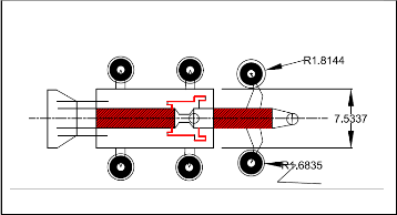
Fig 3.1 2D design of robo
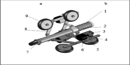
Fig 4.1 Essential parts of robot
International Journal of Scientific & Engineering Research, Volume 5, Issue 7, July-2014 1521
ISSN 2229-5518
The project aims in designing a pipe climbing Robot which is operated using computer wirelessly from a remote location wirelessly using Zigbee modules. The advent of new high- speed technology and the growing computer Capacity provide realistic opportunity for new robot controls and realization of new methods of control theory. This technical improvement together with the need for high performance robots created faster, more accurate and more intelligent robots using new robots control devices, new drivers and advanced control algorithms. This project describes a new economical solution of robot control systems. The presented robot control system can be used for different sophisticated robotic applications.
Zigbee is a PAN technology based on the IEEE 802.15.4 standard. Unlike Bluetooth or wireless USB devices, Zigbee devices have the ability to form a mesh network between nodes. Meshing is a type of daisy chaining from one device to another. This technique allows the short range of an individual node to be expanded and multiplied, covering a much larger area.
The project aims in designing “Robot to rescue of a child in a borehole” which is capable of moving inside the pipe according to the user commands given from PC. The project also used for Picking and Placing of objects based on arm design. The robot is operated through PC using wireless Zigbee technology and using wireless camera you can view both audio and video on the TV. This robot has a high power LED which acts as a light source when light intensity inside the pipe is low. It is a low cost robot used to monitor the changes of different parameters in the industrial pipes.
The advent of new high-speed technology and the growing computer Capacity provided realistic opportunity for new robot controls and realization of new methods of control theory. This technical improvement together with the need for high performance robots created faster, more accurate and more intelligent robots using new robots control devices, new drivers and advanced control algorithms. This project describes a new economical solution of robot control systems. The presented robot control system can be used for different sophisticated robotic applications.
The robot is operated through PC using wireless Zigbee technology and using wireless camera you can view both audio and video on the TV. This robot has a high power LED
IJSER © 2014 http://www.ijser.org
International Journal of Scientific & Engineering Research, Volume 5, Issue 7, July-2014 1522
ISSN 2229-5518
which acts as a light source when light intensity inside the pipe is low. It is a low cost robot
used to monitor the changes of different parameters in the industrial pipes.
Zigbee is a PAN technology based on the IEEE 802.15.4 standard. Unlike Bluetooth or wireless USB devices, Zigbee devices have the ability to form a mesh network between nodes. Meshing is a type of daisy chaining from one device to another. This technique allows the short range of an individual node to be expanded and multiplied, covering a much larger area. The controlling device of the whole system is a Microcontroller. Whenever the user presses a button from the keyboard of the PC, the data related to that particular button is sent through Zigbee module interfaced to PC. The robot also has arm to lift the obstacle using servo motor. The system also has head lamp vision with high power LED’s and it gets ON when the LDR sensor detects the darkness inside the bore hole. This data will be received by the Zigbee module in the robot system and feds this to Microcontroller which judges the relevant task to the information received and acts accordingly on the robot and arm movement. The live images from the camera in the robot system can b sent to TV through AV transmitter system. The Microcontrollers used the project are programmed using Embedded C language.
1. Wireless controlling of Robot through PC using Zigbee technology.
2. Live Audio and video can be seen on TV.
3. Implementation of pick and place concept to the robot.
4. DC motor based gripper operation for robotic arms
An embedded system is a combination of software and hardware to perform a dedicated task. Some of the main devices used in embedded products are Microprocessors and Microcontrollers.
Microprocessors are commonly referred to as general purpose processors as they simply accept the inputs, process it and give the output. In contrast, a microcontroller not only accepts the data as inputs but also manipulates it, interfaces the data with various devices, controls the data and thus finally gives the result.
The Project “DESIGN & CONSTRUTION OF PIPELINE INSPECTION & RESCUE ROBOT” using 16F877A Microcontroller is an exclusive project that can move the robot according to the instructions given by the above said microcontroller. The system
IJSER © 2014 http://www.ijser.org
International Journal of Scientific & Engineering Research, Volume 5, Issue 7, July-2014 1523
ISSN 2229-5518
also has a camera that is fixed to the Robot; this project enables the user to capture the image
in any direction using a wireless camera which is connected to a robot that can move with the speed and direction specified by the robot
Fig 3.1 2D design of robo
Fig 4.1 Essential parts of robot
The main parts of the robo are described below . which are shown in the figure 4.1
1. Helical spring
2. Slider
3. Motors
4. Gripper
IJSER © 2014 http://www.ijser.org
International Journal of Scientific & Engineering Research, Volume 5, Issue 7, July-2014 1524
ISSN 2229-5518
5. Warm and warm wheel
6. Links
7. Central element
8. Links
9 .Wheels
1) Central element The term central element is most essential part of this pipe line climbing robot . It works as like a back bone of this project. The links those are attached to this main frame for actuating movement. The central element which is in hallow portion .Which carries links along with wheels for movement of the robot. On the top of the central element one slider will be arranged with hallow portion for freely sliding which is made up of the cast iron six fixed joints for gripping the another links . In this project we are using circular type of the robot for free movement of the slider on it
Fig 4.2 Central Element
length of the hallow tube or rod 45cm
diameter of the hallow tube 28 cm internal diameter of the hallow tube 4 cm external
In this project manufacturing of the central element is made by the cast iron
The following things should be kept in mind while designing the central element
• Cost of the metal
• Durability of the metal
IJSER © 2014 http://www.ijser.org
International Journal of Scientific & Engineering Research, Volume 5, Issue 7, July-2014 1525
ISSN 2229-5518
• Weight of the metal
• Easy for machining
2) Slider
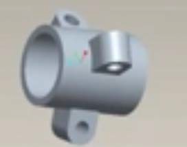
Fig 4.3 Slider
Transitional element is placed on the CENTRAL FRAME.The Frame is Actuating on the
CETRAL FRAME for TO AND FRO motion of the WHEELS Diameter of the slider : 38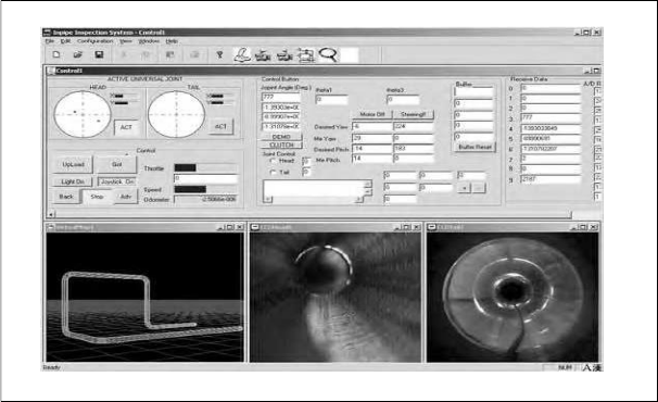
Fig 4.4 .Inside a pipe line
IJSER © 2014 http://www.ijser.org
International Journal of Scientific & Engineering Research, Volume 5, Issue 7, July-2014 1526
ISSN 2229-5518
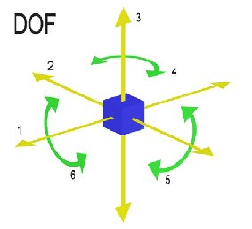
Fig 4.5 (b) number of degrees of freedom
The position of a rigid body in space is defined by three components of translation and three Components of rotation, which means that it has six degrees of freedom. The Exact constraint mechanical design method manages the degrees of freedom to neither under constrain nor
over constrain a device.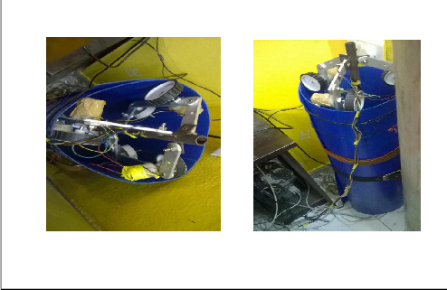
Fig 5.3 robo climbing in pipe
IJSER © 2014 http://www.ijser.org
International Journal of Scientific & Engineering Research, Volume 5, Issue 7, July-2014 1527
ISSN 2229-5518
5.2 . Wheel Leg Mechanism
One of the most important issues in the design of a driving vehicle is how to obtain the traction force enough to pull instrumentation as well as the vehicle itself. Especially in vertical pipelines, it is desirable to keep adequate wall pressing forces in order to ensure sufficient traction forces. Excessive forces may dissipate power and be in danger of damaging the robot. On the contrary insufficient forces may cause the robot to fall down. On the condition that the wheel does not slip on the pipeline surfaces, the traction force is proportional to the friction coefficient and the pressing force between the wheel and the pipeline surface, and the friction coefficient depends on the material of wheel and the surface condition of pipelines. In addition, the link mechanism of the vehicle should minimize the variation of traction force caused by variation of pipeline diameters. Therefore, a leg mechanism has to meet the following three requirements. At first, it should be possible to push against the pipeline wall with adequate pressing forces. In the second, the pressing force should not show significant change during navigation in order to provide stable traction force and flexible locomotion. At last, the mechanism should be simple and small in size to occupy minimal space inside the pipelines. For example, the driving vehicle of MRINSPECT III has three wheeled legs circumferentially spaced 120 degree apart on the main shaft of the vehicle.
Illustrates the kinematic diagram of the wheeled leg mechanism of MRINSPECT III. The mechanism employs a pantograph mechanism with a sliding base that permits the natural folding and unfolding of the leg. Here, l is the length of link, θ means the folding angle of the link measured by the rotary potentiometer, K denotes the spring constant, h represents the distance of the center of the wheel from the base. Fw denotes the wall
Pressing force, Ax and Ay are the forces acting on the link by the spring, x is the displacement of the sliding base. In the proposed mechanism when the wheels are pressed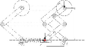
Fig 5.4 wheel leg mechanism
IJSER © 2014 http://www.ijser.org
International Journal of Scientific & Engineering Research, Volume 5, Issue 7, July-2014 1528
ISSN 2229-5518
They just contract or expand along the radial direction. It is a very advantageous feature because undesirable distortion forces are not exerted on the robot when the robot goes over obstacles. Using Fig. 5 we can derive several basic equations necessary for optimizing the
wall pressing forces. First the relation between h and x can be obtained as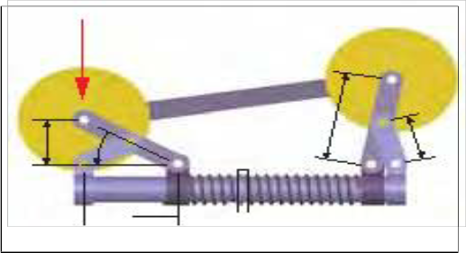
Links calculations:
Fig 5.5 Wheel leg mechanism
To find number of links we have l = 2p-4
To find joints we have the j = (3/2)xl-2
Here l is abbrivated as “ LINKS”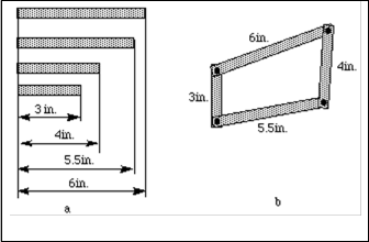
J is abbrivated as the “ JOINTS”
Fig 5.15 Basic Links
IJSER © 2014 http://www.ijser.org
International Journal of Scientific & Engineering Research, Volume 5, Issue 7, July-2014 1529
ISSN 2229-5518
The function of a link mechanism is to produce rotating, oscillating, or reciprocating motion from the rotation of a crank or vice versa Stated more specifically linkages may be used to convert:
1. Continuous rotation into continuous rotation, with a constant or variable angular velocity ratio.
2. Continuous rotation into oscillation or reciprocation (or the reverse), with a constant or variable velocity ratio.
3. Oscillation into oscillation, or reciprocation into reciprocation, with a constant or variable velocity ratio.
Linkages have many different functions, which can be classified according on the primary goal of the mechanism:
• Function generation: the relative motion between the links connected to the frame,
• Path generation: the path of a tracer point, or
• Motion generation: the motion of the coupler link.
The project “DESIGN AND CONSTRUTION OF PIPELINE INSPECTION AND RESCUE ROBOT” was designed to construct a Robot which is capable of climbing thepipeline. The robot was operated using computer wirelessly using zigbee from are motelocation and also such that Robot can move either Forward by pressing button ‘f’ or Backward by pressing button ‘b’, from the PC through the Hyper Terminal. This robot has high power LED which acts as a light source inside the pipe.
Integrating features of all the hardware components used have been developed in it. Presence of every module has been reasoned out and placed carefully, thus contributing to the best
working of the unit. Secondly, using highly advanced IC’s with the help of growing
IJSER © 2014 http://www.ijser.org
International Journal of Scientific & Engineering Research, Volume 5, Issue 7, July-2014 1530
ISSN 2229-5518
teclmology, the project has been successfully implemented. Thus the project has been successfully designed and tested.
IJSER © 2014
International Journal of Scientific & Engineering Research, Volume 5, Issue 7, July-2014
ISSN 2229-5518
1531