International Journal of Scientific & Engineering Research, Volume 4, Issue 4, April-2013 464
ISSN 2229-5518
Cracking strength of steel fiber reinforced concrete shallow beams under impact actions
James H Haido, Ismaeel H. Musa
Abstract— The relationship between impact resistance of steel fiber reinforced concrete wide beams and the length of steel fiber used have been investigated in present endeavor. Two fiber sizes have been adopted in current experiments namely 2 cm and 4 cm with two shapes which are hooked ends and corrugated. The impact resistance of concrete wide beams has been measured in terms of number of blows required to make first crack, first diagonal crack and collapse of the beams. Finite element analysis has been implemen ted for the beams by using tetrahedral and hexahedral elements in ANSYS Workbench 14. Regression analysis was employed to find r easonable relationships for impact capacity and ductility of the wide beams in terms of long fiber contents. It was concluded that the long fibers improved the ductility and impact resistance of wide beam by a percentage of 45.66% more than that in case of using short fibers. Present finite element simulation proved the validity of using the tetrahedral elements with RHT nonlinear model in ANSYS for the cas e of steel fiber reinforced concrete shallow beams.
Keywords— shallow reinforced concrete beam, impact absorption capacity, solid finite elements
1 INTRODUCTION
—————————— ——————————
ide beams are characterized by their large width which approximately equivalent to twice of their total depth or more [1-3]. According to related reinforced concrete
codes, no shear reinforcement is required for concrete wide beam as usual. Nowadays, shallow beams are widely used in concrete constructions such as residential buildings, garages, bridges etc.
Impact forces are special cases of impulsive dynamic loads. The collision of objects with structural elements is considered the main sources of impact actions. The impact bodies can be separated into two sorts namely soft (deformable) and rigid objects [4]. The concrete structures which subjected to free fall bodies or projectiles are almost represented as single concen- trated forces, while, detonations will produce the distributed impact actions on a structure. Concrete is a brittle material so it has low impact resistance which based mainly on impact force rate [5-9]. It has been demonstrated previously that the performance of concrete structures under shear and bending will improved with introducing steel fibers [10-15]. Impact resistance is considered as an important parameter to assess the dynamic behavior of reinforced concrete material [16].
Present endeavor involved the investigation of perfor- mance for concrete shallow or wide beams which contain steel fibers with different sizes. In addition to that, current work included the simulation of the impact behavior of these wide beams by using finite element modeling available in ANSYS
————————————————
James H Haido is currently lecturer at University of Duhok, Iraq., PH-
009647504503573. E-mail: james.haido@uod.ac
Ismaeel H. Musa is currentlylecturer at Duhok Polytechnic University,
Iraq.
workbench 14 program.
2 RESEARCH SIGNIFICANCE
Present study demonstrates the effect of steel fiber size on the improvement of impact energy and ductility of concrete wide beams. Current investigation is represented as a first endeavor toward the investigation of impact resistance of steel fiber re- inforced concrete wide beams with different steel fibers aspect ratios.
3 EXPERIMENTAL INVESTIGATION OF IMPACT RESISTANCE FOR STEEL FIBER REINFORCED CONCRETE WIDE BEAMS
The experimental program in present study included briefly the casting of wide beam specimens and performing the im- pact behavior test as explained in the following sections:
3.1 Preparation of Steel Fiber Reinforced Concrete
Wide Beam Samples
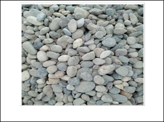
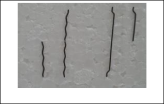
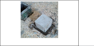
The key materials that used in preparing the sample are Ordinary Portland Cement OPC with specific gravity of 3.15, river sand with fineness modulus of 2.5 , rounded local Iraqi gravel (Fig. 1) with bulk density of 2600 kg/m3 and maximum size of about 20 mm, tap water with a ratio of 50% of the used cement weight per con- crete mix and steel fibers with different shapes namely hooked ends and corrugated fibers (Fig. 2) with an equivalent diameter of 1 mm and lengths of 40 mm and 20 mm. Two steel fiber contents that are 10 kg/m3 and 20 kg/m3 have been adopted in present experi- ments to reinforce the concrete. The concrete mix has been de- signed according to the main material proportions listed in Table 1. Present mix has been used in casting of all concrete specimens. Concrete cubes with size of 15 cm (Fig. 3) have been made with using aforementioned steel fibers types and concentrations. These cubes were used for compression strength test. Many shallow
IJSER © 2013
http://www.ijser.org
International Journal of Scientific & Engineering Research, Volume 4, Issue 4, April-2013 465
ISSN 2229-5518
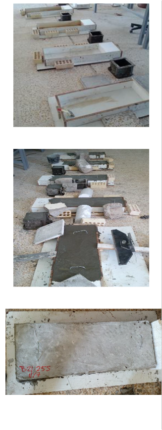
(wide) beams (Fig. 4) have been prepared with different steel fibers contents that depend on the amount of both long and short fibers. The detailed mixture compounds of the fresh concrete are given in Table 2. The number of samples per each mix is two.
Fig. 1. Local coarse aggregate (gravel)
Fig. 2. Used steel fibers
TABLE 1

FRESH CONCRETE MIXTURE COMPONENTS
Ordinary Portland Cement - OPC
Sand
(kg/m3)
Gravel
(kg/m3)
Water
(kg/m3)
Steel fibers
(kg/m3)
(kg/m3)
429.8 644.7 1074.5 214.9 10 and 20
Fig. 3. Concrete cube for compression test
IJSER © 2013
ttp://www.ijser.org
International Journal of Scientific & Engineering Research, Volume 4, Issue 4, April-2013 466
ISSN 2229-5518
F S
3.2 Procedure of Current Experimental Tests
Standard compression strength test steps according to the Iraqi standards for concrete material [17] were employed to measure the compression strength after 28 days of curing at 25oC.
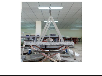
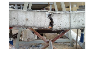
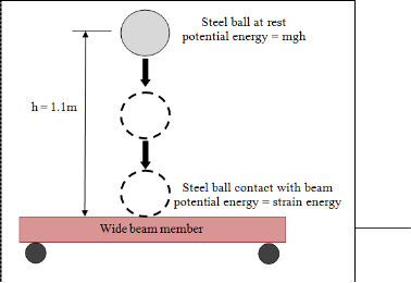
Shallow beams were tested under the effect of impact load created by a steel ball with weight of 7.4 kg and diameter about 12 cm dropped in free fall from the height of 1.1 m above the top surface of the wide beam (Fig. 5). The ball contacts with the shallow beam at a specified point (mid span location) so it is considered as a con- centrated single impact force. The beam is rested on steel tubes and the supports are partially fixed as depicted in Fig. 5.
IJSER © 20
Fig. 5.Concrete wide beam specimen under the force of dropped steel ball
http://www.ijser.org
International Journal of Scientific & Engineering Research, Volume 4, Issue 4, April-2013 467
ISSN 2229-5518
3.3 Experimental Outcomes
3.3.1 Compression Test Result
The compression strength values for concrete cubes refer to im- provement in strength with increasing the fiber length or fiber as- pect ratio as appeared in Fig. 6. It is obvious also that the strength increased with increasing of fibers dosage by a percentage of about
16.34%. However, the steel fibers may not have great role in im- proving the compression strength of concrete material but they have this role in increasing the tensile strength of concrete due to the fact of arresting the cracks which generate from the applied loading.
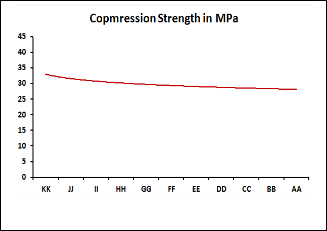
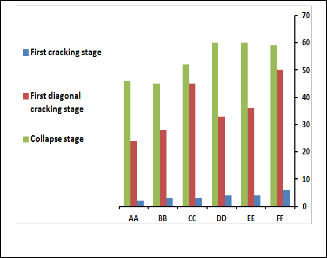
Fig. 7. Number of steel ball blows to produce cracking for wide beams with steel fiber content of 10 kg/m3
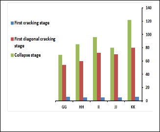
Fig. 5. Compressive strength of present concrete cubes
3.3.2 Initial Cracking, Diagonal Cracking and Collapse
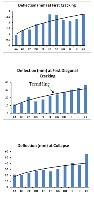
The wide beam failure has been investigated in three forms namely first crack at any direction, first diagonal crack and collapse (final crack formation). The number of blows for the dropped steel ball on the beams to form first crack, diagonal crack and collapse or final cracking stage is given in Figs. 7 and 8. After the occurring of first crack, the dropping of ball on the wide beam was continued until the impact strength at diagonal crack was reached. According to the test outcomes which given in terms of the required ball blows to make a diagonal crack in beam body, it can be said that the diagonal failure is the intermediate failure stage between the first bending cracking stage and collapse stage. The strength of wide beams which contain long fibers alone at first crack and first diagonal crack is considered the best one compared to the other beam cases which have been observed in the recorded data in the Figs. 7 and 8. After this mid cracking stage or diagonal crack (Fig.
9), the blows of ball were kept on till achieving the eventual failure. The collapse of the wide beams was usually appeared in the form of splitting the beam into two main pieces as shown in Fig. 10.
The presence of steel fibers at both sides of cracking surfaces has been seen which indicates the great role of these randomly distrib- uted fibers to bridge these sides (Fig. 11). In dependence on the data in Fig. 12, it can be demonstrated that using long steel fibers in wide concrete beams led to delay the collapse of the beam by per- centages of 32.5843% and 76.6% compared to beams reinforced with short steel fibers alone with dosages of 10 kg/m3 and 20 kg/m3 respectively.

Fig. 8 Number of steel ball blows to produce cracking for wide beams with steel fiber content of 20 kg/m3
Fig. 9. Diagonal cracking of wide beam
IJSER © 2013
http://www.ijser.org
International Journal of Scientific & Engineering Research, Volume 4, Issue 4, April-2013 468
ISSN 2229-5518
k = flexural stiffness of the wide beam = 48 x modulus of elasticity of beam x beam moment of inertia / (length of beam)3 [19] (5)
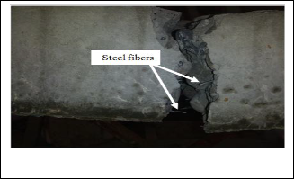
Fig. 10. Collapse of wide beam
Fig. 12a
Fig. 11 Fibers at cracking interfaces on cracked wide beam
3.3.3 Absorbed Energy by Wide Beam
The mechanics matter involved in present experiments is repre- sented in the steel fiber reinforced concrete wide beam perfor- mance that given as a function of absorbed gravitational potential energy as hereunder [18]:
Gravitational potential energy = weight of falling ball x dropping height of the ball above the target (wide beam) (1) As the steel ball falls from the rest at the height of 1.1 m as in pre- sent work, the gravitational potential energy is changed to kinetic energy after contacting the wide beam. This transformation of en- ergy can be given in the following relationship:
Kinetic energy = Potential energy (2)
or
0.5 x mass of falling ball x (ball velocity)2 = mass of ball x gravita-
tional acceleration x dropping height (3)
The converting of these aforementioned energies is called the con-
servation of energy which can be expressed graphically as illustrat-
ed in Fig. 13.
Based on the conservation of energy, the potential energy (input to
the beam) is equal to the output energy (strain energy or energy produced by the deformation of the beam), thus:
m x g x ( h + ∆ ) = 0.5 x k x ∆2 (4)
where
m = mass of the steel ball in kg
g = gravitational acceleration of 9.81 m/s2
h = dropping height of 1.1 m measured from the center of ball to
the top surface of the wide beam
Fig. 12b
Fig. 12c
Fig. 12. Deformation of wide beam at different cracking stages
∆ = dynamic deflection generated from the hit of steel ball and the beam = ∆s x (1+(1+2hkK/∆s)0.5) (6)
K = [1+17 x mass of beam / (25 x mass of ball)] / [1+5 x mass of beam / (8 x mass of ball)2] (7) The impact strength was influenced directly by the density or mass of target (shallow beam) as illustrated in Fig. 14. Thus, in the other
IJSER © 2013
http://www.ijser.org
International Journal of Scientific & Engineering Research, Volume 4, Issue 4, April-2013 469
ISSN 2229-5518
TABLE 3
ABSORBED IMPACT ENERGY BY THE FIBROUS W IDE BEAMS AT DIFFERENT CRACKING STAGES

Absorbed
Concrete type designation
AA BB CC DD EE FF GG HH II

JJ KK
Absorbed
energy at first crack- ing (N.m)

162.8
244.2
244.2
284.9
284.9
447.7
284.9
366.3
529.1
366.3
366.3
energy at first diagonal cracking (N.m)
1953.6
2238.5
3744.4
2645.5
2889.7
3052.5
4354.9
4843.3
5820.1
5698
6512
Absorbed
energy at collapse (N.m)
3744.4
3622.3
4070
3988.6
3703.7
4802.6
5616.6
6878.3
7773.7
6512
9890.1
Fig. 14. Best trend line relationship between wide beam mass and absorbed energy
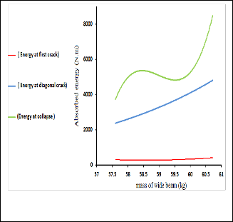
words, the number of blows or the absorbed impact energy and ductility of the beam are increased with increasing the mass of the beam.
Best impact performance has been exhibited by the wide beam reinforced with long steel fibers and large fiber content as shown in Table 3. Where, the increasing has been seen in the impact re- sistance (absorbed impact energy) for fibrous concrete wide beams contain long fibers by about 60.2067% more than the resistance of wide beam with short steel fibers alone.
It was also demonstrated that the ductility was improved by intro- ducing long steel fibers in the wide beam fabrication. This can be observed in improvement the deflection at first cracking, first diag- onal cracking and collapse stages of the wide beam by approxi- mately of 56.26%, 43.88% and 36.85% respectively for a wide beam contains long fibers alone with comparison to beam with short steel fibers alone.
4. Simulation of Wide Beam Behavior with Finite
Element in ANSYS Workbench 14 Program
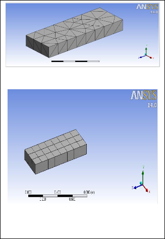
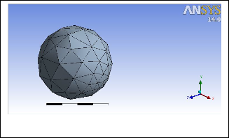
Different material behaviors treated in engineering are presented in terms of various differential equations using specified mathemati- cal models of continuum mechanics [20]. Exact solutions for these equations are difficult to determine, thus numerical approaches (such as finite element solutions) are adopted to find the approxi- mate solution of the differential equations. In the other words, the performance of complicated structural systems can be investigated today with using the perfect computer programs which consider numerical analysis [21]. ANSYS Workbench 14 is a premier finite element program which used for analysis of many complicated structural cases such as irregular beams shapes, beam under dy- namic actions, structural elements with complicated boundary conditions etc. ANSYS Workbench finite 14 element program was employed to implement the analysis of present wide beams under the effect of falling ball. The steel ball (Fig. 15) was simulated in this program by using four nodes tetrahedral elements (Fig. 16) with a material model named as structural steel model. The wide beam (Fig. 17) has been modeled in analysis with employing of hexahe- dral solid elements (Fig. 18) and tetrahedral elements incorporated with nonlinear model of concrete material called RHT Concrete Strength. RHT Concrete Strength is considered as the best nonline- ar material constitutive model for concrete in explicit dynamic problem like present analysis case. Originally, the models are de- fined according to present experimental data in the item of engi-
ER © 2013
/www.ijser.org
International Journal of Scientific & Engineering Research, Volume 4, Issue 4, April-2013 470
ISSN 2229-5518
neering data. After that, the structural system was modeled using Geometry or Design Maker subprogram. In subprogram named as Model, the finite element mesh for the beam and ball, support con- ditions of wide beam and the displacement (which is 1.1 m) of the ball over the beam surface were assigned. The explicit dynamic parameters were as follows:
Maximum number of time steps (cycles) = 1E7 cycle
End time of analysis (time of falling or reaching the ball to the wide
beam surface) = 0.47 s
Maximum size of the element = 0.1 m
Maximum energy error = 0.1
Time step = 1E-6 s
Beam solution type = Bending
The solving time for each run was about 40 minutes. The impact or
contact force between ball and the beam are varied with the magni-
tude of wide beam density. The numerical results were given in
terms of the absorbed energy at the first cracking, first diagonal
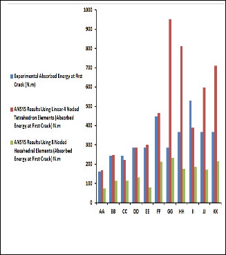
cracking and collapse failure stages as shown in Figs. 19 – 21. Compared to using of hexahedral elements, it was demonstrated that the using of tetrahedral elements in modeling gave more
matching of numerical outcomes to the experimental data. This is referred to the number of elements used in analysis, where this number will increase with using of tetrahedral elements with fixing the maximum size of the element in the analysis. The difference between current experimental and finite element outcomes is at- tributed to the approximation provided in the finite element mod- eling such as neglecting the influence of air friction and beam fric- tion with the steel ball during the free falling and at the contact moment respectively.
Fig. 17a
Fig. 17b
Fig. 17. Finite element meshes for wide beam
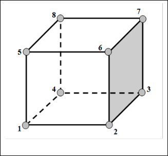
Fig. 15. Steel ball finite element mesh
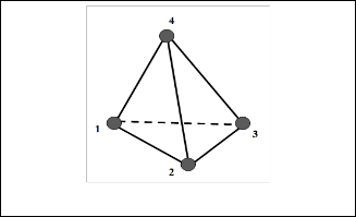
Fig. 18 Hexahedral solid element
Fig. 16. Tetrahedral solid element
IJSER © 2013
http://www.ijser.org
International Journal of Scientific & Engineering Research, Volume 4, Issue 4, April-2013 471
ISSN 2229-5518
Fig. 19. Comparison between present finite element analysis and experimental outcomes for wide beams energy absor ption at first cracking
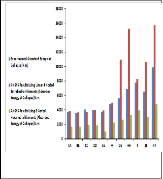
Fig. 21 Comparison between present finite element analysis and experimental outcomes for wide beams energy absor ption at collapse failure
5- Proposed Models for Absorbed Energy and Dynamic
Deflection of Wide Beam
Depending on present experimental test results, mathematical models have been formulated for the impact energy absorption capacity of the wide beams used and their deformation as func- tions of long steel fibers content. The models were found by using a regression of present experimental data in IBM SPSS Statistics 20 program. The models were proposed as the following equations: Absorbed energy at first crack = 0.0001C3 – 0.0458C2 + 6.1763C –
36.5210 (8) Absorbed energy at first diagonal crack = 0.0076C3 – 3.0571C2 +
503.79C – 24497 (9) Absorbed energy at collapse = 0.0058C3 – 2.2441C2 + 356.33C –
14823 (10) Deflection at first crack = 0.0001C3 – 0.0285C2 + 3.1714C – 131.08
(11) Deflection at first diagonal crack = -0.0009C3 + 0.1979C2 – 20.588C +
822.08 (12) Deflection at collapse = -0.0002C3 + 0.0444C2 – 4.0734C + 161.39
(13)
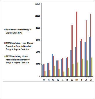
Fig. 20 Comparison between present finite element analysis and experimental outcomes for wide beams energy absor ption at first diagonal cracking
where
C = 800 x steel fibers content + 4 x long fiber content (14)
The index of determination for equations 8-13 is about 80%.
These mathematical models demonstrate the improvement of im-
pact resistance with increasing the length of fibers and their con-
centrations.
6. Conclusions
The relationship between the impact resistance of fibrous wide beam and the length of steel fibers has been investigated in present experimental-theoretical work. The performance of wide beams
IJSER © 2013
http://www.ijser.org
International Journal of Scientific & Engineering Research, Volume 4, Issue 4, April-2013 472
ISSN 2229-5518
has been simulated with the modeling in finite element program i.e. ANSYS Workbench 14. Two elements have been adopted in current analysis namely hexahedral and tetrahedral solid elements with RHT nonlinear model for concrete material. The results have been given in terms of deformation and absorbed energies as func- tions of number of blows for many failure modes of wide beam. According to present experimental and numerical analysis out- comes, the conclusions have been drawn as hereunder:
1- Steel fiber reinforced concrete wide beam with long fibers has the superior impact resistance compared to other beams.
2- The ductility and capacity of impact energy absorption of the wide beams are increased with increasing the aspect ratio or length and content of steel fibers used.
3- In finite element model for wide beam, the using of nonlinear RHT model for fibrous reinforced concrete with tetrahedral ele- ments gives more reasonable results which close to the experi- mental data. The matching between present experimental out- comes and numerical results with using of tetrahedral elements in beam modeling is around 90% in comparison to using of hexahe- dral elements in analysis. In the other words, the hexahedral ele- ments give an underestimating in the outcomes for present simula- tion.
4- The increasing in the mass of wide beams plays a great role in improving the ductility of the beams.
5- The reasonable models for absorbed impact energy and maxi- mum deflection for concrete wide beams influenced greatly by the dosage of long steel fibers and content of steel fibers as all. The cor- relation between the proposed absorbed energy and deformation models with aforementioned long fibers content is considered proper with a correlation coefficient R2 of 80%.
Acknowledgments
The authors are very grateful to the Faculty of Engineering and Applied Sciences at University of Duhok for the finical support for this research. Thank you very much goes to Professor Assistant Dr. Jawhar Rasheed for his assistance.
9- Travas V, Ozbolt J, Kozar I (2009) Failure of plain concrete beam at impact load: 3D finite element analysis. Int J Fracture 160:31-41.
10- ACI Committee 544 (1984) State of the art report on fiber rein- forced concrete. In: Fiber reinforced concrete int., symposium. De- troit: ACI Publication, SP-81, pp. 411–432.
11- Hsu LS, Hsu CTT (1994) Stress-strain behavior of steel-fiber high-strength concrete under compression, ACI Struct. J. 91(4):448–
457.
12- Abdul-Razzak AA, Mohammed Ali AA (2011) Modelling and
numerical simulation of high strength fibre reinforced concrete
corbels. Appl Math Model J 35(6):2901–2915.
13- Abdul-Razzak AA, Ali AAM (2011) Influence of cracked con-
crete models on the nonlinear analysis of high strength steel fibre
reinforced concrete corbels. Compos Struct 93:2277–2287.
14- Haido JH (2012) Prediction of static behavior for SFRC deep
beams using new and simple nonlinear models. Caspian J Appl Sci
Res 1(5):1-26.
15- Haido JH (2012) Investigation of SFRC corbel performance us- ing a developed nine-noded lagrangian elements. ARPN J Eng and Applied Sci 7(8):963-970.
16- Liu F, Chen G, Li L, Guo Y (2012) Study of impact performance of rubber reinforced concrete. Constr Build Mater 36:604–616.
17- Building Research Center, Scientific Research Council- Iraq (1987) Iraqi building code requirements for reinforced concrete, Code 1.
18- Rao HS, Ghorpade VG, Ramana NV, Gnaneswar K (2010) Re- sponse of SIFCON two-way slabs under impact loading. Int J Im- pact Eng 37:452–458.
19- Karnovsky IA, Lebed O (2010) Advanced Methods of Structural
Analysis. Springer Science+Business Media, LLC.
20- Nakasone Y, Yoshimoto S, Stolarski TA. (2006) Engineering
analysis with ANSYS software. Elsevier Butterworth-Heinemann
Linacre House, Jordan Hill, Oxford OX2 8DP 30 Corporate Drive,
Burlington, MA 01803.
21- Tavazo H, Estekanchi HE, Kaldi P (2012) Endurance time
method in the linear seismic analysis of shell Structures. Interna-
tional Journal of Civil Engineering 10 (3):169-178.
References
1- American Concrete Institute ACI committee-318 Code (1971) Requirements for structural concrete and commentary.
2- American Concrete Institute ACI committee-318 Code (2005) Requirements for structural concrete and commentary.
3- Prota A, Tan KY, Nanni A, Pecce M, Manfredi G (2006) Perfor- mance of shallow reinforced concrete beams with externally bond- ed steel-reinforced polymer. ACI Struct J 103(2):163-170.
4- Ozbolt J, Sharma A (2011) Numerical simulation of reinforced concrete beams with different shear reinforcements under dynamic impact loads. Int J Impact Eng 38: 940-950.
5- Brandon DG (1987) Dynamic loading and fracture. In: Blazynski
TZ, editor. Materials at high strain rates. Elsevier, pp. 187-218.
6- Ozbolt J, Rah KK, Mestrovic D (2006) Influence of loading rate
on concrete cone failure. Int J Fracture 139:239-252.
7- Ozbolt J, Sharma A, Reinhardt HW (2011) Dynamic fracture of
concrete compact tension specimen. Int Jr Solids Struct 48:1534-
1543.
8- Saatci S, Vecchio JV (2009) Effect of shear mechanisms on impact
behavior of reinforced concrete beams. ACI Struct J 106(1):78-86.
IJSER © 2013
http://www.ijser.org