International Journal of Scientific & Engineering Research, Volume 5, Issue 7, July-2014 1071
ISSN 2229-5518
Consideration of security in the design process
Alami Ayoub. * Naciri oumaima.* Herrou Brahim. ** El Hammoumi Mohammed. **
Abstract— Detailing the integration of security design model This article aims. It is a systematic integration and earlier security during the devel- opment of the industrial system. The objective is to take into consideration the security inherently in the design of final industrial system.
To do this we derive the characteristics of the correspondence points (or mapping) between design and security. We offer three types of interaction design with man. We have created a process of risk evolving with a design process mutually reinforcing. This process of risk admits six contexts of risk analysis.
Index Terms— integration, security, design, risk mapping process.
—————————— ——————————
1 INTRODUCTION
In general, the design is based on four characteristic stages of development of the industrial system requirement definition, research concepts, research on the structure of the solution and establishment of comprehensive industrial system. These steps clearly reflect the types of modeling to do in order to achieve industrial system that meets the needs of the user.
The model we propose for the integration of security into the design is developed in the process of systematic design de- scribed by [6] and based on four characteristic steps: clarifica- tion of tasks or the definition of customer needs, conceptual design, architectural design and detailed design of the indus- trial system. A systematic approach has the advantage of be- ing an algorithmic approach, that is to say, it describes the best path to achieve a goal. However, when it comes to designing a well-defined goal, these approaches are impractical because some steps can merged [8]. Pahl and Beitz were the first to describe the design process as a systematic process [6]. We retain the advantage of this approach precise and structured description of any industrial system throughout its develop- ment process. The first stage of planning and clarification of tasks in the transcription phase of customer needs in terms of functions. In the end, this step leads to a first draft of a specifi- cation (CoC) expressing the requirements that the industrial system is intended to satisfy the user.
Typically, this step is the subject of descriptive tools need (FIT) and external functional analysis (octopus diagram). Thus at this level, security objectives can be integrated as accidents or statistical annex of the CoC report; or through the characteri- zation of the type of users, considered adapting elements (also called elements of the environment of use) of the industrial
system.
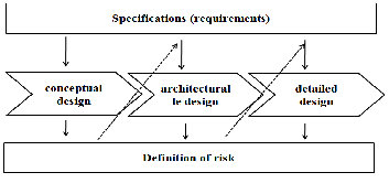
The model of integration of design and security is shown in Figure 1. CoC content and hence the clarification step tasks are considered in parallel with the three stages of conceptualiza- tion of the industrial system. Definition (or identification) risk is performed at each step of the design process. Thus, the risks are considered to be operating simultaneously with the design and technological choices. Security requirements developed during the design are introduced in the CoP. This definition of risk and the development of security requirements are what we call the "process of risk".
Why are we talking about a process of risk? As explained, the risks defined over the design and hence the security require- ments depend on the step of corresponding design. Hence, the nature of requirements and hence their impact on the design and the user are not the same. Just as the effects of technologi- cal choices made at each step are not similar in terms of added value in the design of the industrial system. The evolution of knowledge about the risks and effects is therefore a process of risk.
In summary, the integration of security earlier in the design of industrial system is to (1) identify risks through analysis of technology choices and feedback (2) translate these risks secu- rity requirements and (3) take into account these requirements systematically in the synthesis of new solutions as well as technical requirements.
————————————————
*Ayoub Alami Doctorant, FST FES, Industrial technology laboratory, uni- versity SMBA, B.P. 2202; ayoub.alami@usmba.ac.ma
*Oumaima Naciri Doctorante, FST FES, Industrial technology laboratory, university SMBA,B.P. 2202 ; oumaima.naciri@usmba.ac.ma
**Brahim Herrou Professor, EST FES, Industrial technology laboratory, university SMBA, B.P. 2202 ; herroubrahim@yahoo.fr
**Mohammed El hammoumi Professor, FST FES, Industrial technology la- boratory, university SMBA, B.P. 2202; m_elhammoumi@yahoo.fr
IJSER © 2014
Fig 1: Proposed for integrating security earlier in the design model
http://www.ijser.org
International Journal of Scientific & Engineering Research, Volume 5, Issue 7, July-2014 1072
ISSN 2229-5518
2. MAPPING THE DESIGN PROCESS OF RISK PROCESSES
The word mapping is defined as the mapping. Mapper is to establish a correspondence between two objects. In our model to take account of security in the design, we mean by mapping the development and description of the relationship between design and security. The design process is accompanied by a process of identifying and evaluating risks that we have called "process risk".
How these two processes evolve?
First, the design begins with the establishment of a number of key functional requirements (which are rather technical na- ture) resulting in an abstract manner to customer. These re- quirements will be used to define the design parameters first. Mapping functional requirements to design parameters is per- formed iteratively and in a well-defined law (independence axiom). The description of the first design parameters (called technical solutions) will enable early identification and defini- tion of risk. The risk takes effect when the level exceeds the limits of the human. Thus, risks are identified through analy- sis of the possible interaction of the technical solution with the characteristics of the human. Analysis of this interaction on the one hand implies a knowledge of the nature of the re- sources contained in the technical solution and other knowledge of the characteristics of man. As explained, the technical solution (in physical form) has three levels of de- scription (or model) following the progress of the develop- ment of the industrial system. Each level recognizes its own resources. The process may also recognizes three levels of de- scription of risks according to human interaction (set by hu- man characteristics) with the nature of the available physical solution to a particular stage of design resources.
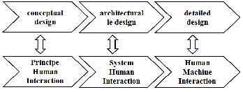
Fig 2: Mapping between process design and process risk
Accordingly, the design process interacts with a process of risk is similarly divided into three stages which we have called interactions. Thus, we note three types of interactions depend- ing on the level of abstraction of the solution:-Human Interac- tion Principle (IHP)-Human Interaction System (IHS), Human- Computer Interaction (HCI). Figure 2 illustrates the corre- spondence between the process design and process risks. The IHP is the description of the interaction characteristics of the man with the resources of the design stage of conceptual de- sign. The IHS is the description of the interaction characteris- tics of the man with the resources of the design stage of archi- tectural design. The HMI is the description of the interaction characteristics of the man with the resources of the design to
the detailed design stage.
2.1 Interactions of the human with the design
The process of risk is divided into three types of interaction: Human Interaction Principles (IHP)-Human Interaction Sys- tem (IHS) and Human-Computer Interaction (HCI) each cor- responding to a stage of the design process. We consider that risk to an effect when it reaches man. Thus, during the design, we assume by default that for a given task, the man is interact- ing with the corresponding physical design characteristics.
2.1.1. Human Interaction Principles
This interaction corresponds with the stage of conceptual de- sign of the design process. From the point of view of design, this step is to decompose the main requirements and sub- requirements to select or principle (s) of solution. Interactions with humans are of two types. The first type is those relating to the environment of use, which are known risks and express- ible in terms of functional requirements. The second type of interaction that is directly related to the nature of physical quantities contained in the principle of solution selected. In the latter case, the requirements are generated for the selected physical solution. At this stage of the design requirements are divided between the industrial system and the human. The principle proposed solution can therefore go full automation of the solution to a completely manual solution. From this fol- lows a human activity (typical use) from the manipulation commands to work handling and a full presence in the work- space. In the case where there is no feedback, the risks associ- ated with physical quantities can be derived from regulations and standards (such as design standards and risk assessment).
2.1.2. Human-System Interaction
This interaction corresponds with the architectural design stage of the design process. From the point of view of design, technical and physical structure of the industrial system are established and occupied space requirements is defined. First- ly, the dangerous zones (energy) associated with the selected solution and the other places of the human intervention may be specified. Hazardous areas are characterized by shape, vol- ume, location and severity. The shape is selected depending on the kind of energy. The volume depends upon the energy level present in the solution. The location is the result of the functional structure and the structural arrangement of the principles of solution. Finally, the severity depends on the energy level and the possible effects on humans. These effects depend on the location of man in relation to the areas and there will result the seat of the lesion. Thus, depending on the effects on humans tolerated, the solution is accepted or reject- ed.
At this stage of design, human interactions are again of two types. First, there are those on the use environment that relate more specifically to the man through the specification of its human characteristics that are known and expressible in terms of constraints. And there are those directly related to the na- ture of the structural parameters of the selected solution. In
IJSER © 2014 http://www.ijser.org
International Journal of Scientific & Engineering Research, Volume 5, Issue 7, July-2014 1073
ISSN 2229-5518
this second case of interaction requirements are generated for the selected physical and solution are expressed as functional security detail requirements.
2.1.3. Human-Computer Interaction
This interaction corresponds to the stage of detailed design of the design process. From the point of view of design, plans definition of the industrial system are established and the choice of components, materials, ... is realized. Note that this interaction is the step after which the risks are traditionally analyzed and corrective actions are implemented detailed so- lution. In our approach, the risk of accidents and major usabil- ity problems are treated in the previous steps. Here, we focus on the study of the effect of selected components on human characteristics. As in the preceding step, these components are described by the physical characteristics. We study the nature of the interaction of these characteristics with those of man. It is to treat juveniles remaining risks in the industrial system. The analysis of failure modes may also be subject to this level of interaction. But that really does make sense vis-à-vis human security if there are risks from the preceding steps have not been resolved to the corresponding step. Finally, interactions with humans, at this stage of the design, derived mainly from the technical solution and are expressed as functional security requirements.
3. DESCRIPTION OF THE DESIGN PROCESS OF THE MODEL
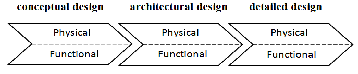
As illustrated in Figure 3, the requirements of CoC involved in the three stages of the design. Thus, depending on the nature of the requirement and the level of abstraction, it will respond to either the design stages. More functional requirements, even techniques, are never fully defined at the beginning of the design. It is thus clear that the process of the industrial system is accompanied by physical integration and ongoing development requirements. Accordingly, each step of the de- sign process is divided into two areas: physical and functional. Functional area corresponds to the technical requirements and the physical realm to technical solutions.
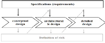
Fig 3: Functional view and physical view of the design process
Thus, in our design process every step of conceptualization of the systematic approach defined by [6] admits a functional view and a physical view. The clarification step task is consid- ered to be operating simultaneously with the other three steps. Therefore, we have a representation of the design as shown in Figure 4.
Fig 4: Design Process Model
Indeed, the design process presented above is based on the design process described by [2] and called extended axiomatic design (Extended Axiomatic Design noted EAD). The EAD is a two-dimensional process linking the systematic approach [6] and axiomatic design [7]. It considers that each of the three stages of the systematic approach (conceptual, architectural and detailed), corresponding to the physical development of the solution is divided into four areas: customer, functional, physical and process. Thus, the requirements identified in the clarification stage of the systematic approach tasks are divided according to their nature and level of abstraction in three stag- es. The contribution of this description of the design process is to cover the shortages of both axiomatic and systematic ap- proaches and highlighting their complementarity. The sys- tematic approach is a description of multiple tasks to do (what) to lead the development of the industrial system. In any case, this approach explains how to perform these tasks (the How) considered as a phase of creativity. This lack shows the need to complement this approach with an approach that explains how to transition from what. Indeed, the axiomatic design gives the laws of the transition of the functional area (what) the physical domain (the how). In our work, we limited ourselves to the functional and physical domains. The design process that we hold is a process that is both systematic and iterative and consists of six phases (denoted Pi (i = 1 .. 6)) as shown in Figure 5.
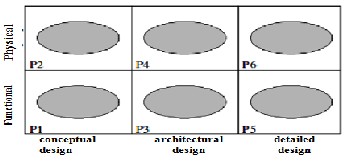
Fig 5: The design process in six phases
But what happens specifically in each phase? How the indus- trial system be modeled? The following paragraphs draw up typologies modeling of the industrial system in each phase of the design.
3.1 Phase 1 (P1): Requirements conceptualization
This phase has as an input the overall requirement (denoted FR) faithfully reflecting the desire of the client. This require- ment admits a (more abstract) level of abstraction 0. It is link- ing two elements of the operating environment (EMU). Thus, an EMU is through the industrial system design on another EMU
IJSER © 2014 http://www.ijser.org
International Journal of Scientific & Engineering Research, Volume 5, Issue 7, July-2014 1074
ISSN 2229-5518
. It is usually expressed by a verb in the infinitive + 2 + EMUs supplements
. This formulation should be independent of any constructive solution.
Example of formulating a FRi: in the case of tractor tools bonds overall requirement phase coupling of a worn tool must be formulated as follows: Wear the tool and not the tractor Linking tool tractor. The overall requirement should be closest to the desire of the user. Indeed, the second formulation is governed by existing technical solutions.
Decomposition of the overall requirement in sub-requirements (or major requirements) - Depending on the complexity of the problem, the overall requirement is in turn more or less com- plex. The complexity of a requirement means that the relation- ship between the two corresponding EMUs is not transparent, which means that the number of components is that it will generate relatively large. Indeed, in the same way that a sys- tem can be decomposed into components and subsystems, an overall requirement can be divided into smaller sub- complexity requirements. The objective of this decomposition is twofold; First it identifies the key requirements that will facilitate the search for solutions, then it combines these re- quirements in a simple functional structure and unambiguous.
The functional decomposition of the base is derived (1) the characteristics of the overall requirement of EMUs and those of the same overall requirement; (2) the first principle of solu- tion imagined (in the physical realm) corresponding to the most abstract global requirement.
At this stage of the design, functional decomposition stops when the solution satisfying the principle of sub-requirements defined. Below is a list of the types of objects that form this phase:
• industrial system - which the user feels the need and
/ or feels the desire, including its implicit expecta- tions.
• Life Cycle industrial system - set of all situations in which there is (or find) the industrial system during his life, from the expression of his need until decom- missioning.
• Life Profiles of the industrial system - all situations
the industrial system in its use phase. These situa- tions can be manual or non-manual (storage, mainte- nance, ...).
• Requirements conceptualization (or Key) - require- ments which express the desire of the user and from the decomposition of the overall requirement to the stage of conceptual design. Generally, the level of ab- straction of these functional requirements varies be- tween 0 and 3.
• constraints (Csi) - limitations on the freedom of the
designer deemed necessary by the applicant of vari- ous kinds such as deadlines, standards, security ....
• Elements of the operating environment (EMU) - ele- ments interacting with the industrial system in the phase of life considered.
• criteria Variables - variables that a functional re-
quirement must meet to be accepted so that the solu- tion is valid. These variables correspond to an inter- val at both terminals.
• Values EMUs - level matching solution. This is usual- ly. a limit beyond which the solution is not accepted;
• Users - types of users. This object describes the char-
acteristics of the target
3.2. Phase 2 (P2): Principle of the solution
From the overall requirement, one or more principles are pro- posed solutions. Search principles of solutions is guided by methods and tools solutions. For each functional requirement, several principles of solutions may be possible.
Decomposition of the principle of sub-principles solution - If the complexity and level of abstraction of the problem allow a functional decomposition (in the functional area), this will result in the physical domain decomposition of principle solu- tion in sub- principles. Thus, it is necessary to find one or more ingredient (s) of solution for each sub-requirement. The sub-combination of these principles will generate the principle solution of the solution. A principle of solution must reflect the physical effects constituting the solution to fill the corre- sponding functional requirement. The analysis of the decom- position (or functional structure) will identify the sub- requirements that require the search of a new principle solu- tion for those that standard solutions may be used.
To find a solution principle of sub-requirements, it is always useful to consider the following: (1) focus on the first sub- requirements that determine the principle of detailed solution and for which there is no standard solution; (2) whether the principle of solution is not standard, it must derive physical effects. Otherwise, it is necessary to choose the appropriate settings (functional geometry, materials and necessary move- ments). It is helpful to use checklists to stimulate new ideas;
(3) the solutions in an intuitive way must be analyzed in order to highlight the key criteria for the evaluation of a particular principle of solution; (4) comparing the solutions made according to the characteristic properties of each solution principle.
Among the criteria for selection and comparison to the stage of conceptual design, we find [6]:
• The characteristics of the principle of solution; sim- plicity and clarity of operation, the adequacy of the physical effect in question with the needs of the de- sign.
• The structural data; a minimum number of compo-
nents, complexity minimum space required.
• Quality control; requires a minimum number of tests and monitoring, simple and reliable procedure.
IJSER © 2014 http://www.ijser.org
International Journal of Scientific & Engineering Research, Volume 5, Issue 7, July-2014 1075
ISSN 2229-5518
• Transport; risks related to the energy in case of transport. Below is a list of the types of objects that form this phase:
• Physical effect of the principle of solution - scientific
effect that allows for the "movement" necessary;
• Energy - type of energy that the principle of solution contains;
• Level of energy available - maximum intensity of en-
ergy use;
• Characteristics of interfaces with EMUs - main di- mensions, spacing, positioning necessary;
• Methods of propagation of energy - the type and
manner in which the energy propagates between the elements;
• Physical quantities - physical characteristics explain- ing how the physical principle of the solution;
• Design Parameters - unquantified parameters that
will allow to define the industrial system. The majori- ty of these parameters is identified and quantified over design.
3.3. Phase 3 (P3): Requirements structuring
This phase has as an input terminal functional requirements of the tree to the stage of conceptual design. These are the main requirements needed explaining the features of the industrial system. At the stage of architectural design, these require- ments will be divided into sub-requirements.
As the requirements of the stage of conceptual design, these requirements can be expressed by a verb in the infinitive + 2 + EMUs supplements. These requirements will express the type of relative movement between the principles of solutions se- lected in phase 2 and thus refine the structural arrangement of the functional groups of the solution.
Decomposition of the requirement sub-requirements - As with the overall requirements, the requirement of first hierarchical and on this stage of the design (called requirement mother) level is in turn more or less complex. To reduce this complexi- ty, the parent requirement is decomposed into sub- requirements of any complexity.
The objective of this decomposition is twofold; First facilitate the search for solutions; then combine these solutions into one responding to the parent requirement.
The basis of the functional decomposition is derived (1) the characteristics of EMUs or components of the parent require- ment and those of the parent requirement; (2) and the first principles of solution devised in the physical realm in previ- ous phases of the design. Traceability of choices (functional and physical) is stored in a tree to allow more refinement in line as possible with the original objectives and the solution to avoid redundant or coupled designs.
At this stage of the design, functional decomposition stops when all requirements defining the relationship and conse- quently the type of bonds and the various major components of the industrial system have been identified. Below is a list of
the types of objects that form this phase:
• Requirements structuring - requirements that deter- mine the relative positioning, movement direction, the necessary flow.
• criteria Variables - variables must comply with a re-
quirement to be accepted so that the solution is valid.
• space constraints - constraints that determine the spa- tial positioning of the solution and its first dimension;
• temporal constraints - constraints that determine se-
quencing of how different principles;
• constraints of resistance to the environment - con- straints that determine the torque weight / material;
• Assembly Constraints - Constraints compatibility be-
tween different types of energy.The values of these requirements can come from both the use situation of the industrial system and other situations of life recy- cling, production, dismantling installation ....
3.4. Phase 4 (P4): Structure of the solution
From functional requirements, one or more principles are proposed solutions. Search principles of solutions is guided by methods and tools for resolving technical problems. In this phase, the principles of links correspond to solutions which will allow the arrangement of the structure of the solution.
Decomposition of the principle of solution components and connections - The result of this design step is to define the structure of the solution. If the complexity and level of abstrac- tion of the problem allows a functional decomposition (in the functional area), this will result in the physical domain de- composition of principle solution in sub-principles. Thus, it is necessary to find one or more solutions for each requirement. The combination of these solutions will generate the structure of the solution.
The analysis of the decomposition (or functional structure) will identify the requirements that require the search of a new principle solution for those that solutions or standard compo- nents can be used. First and assumed solution (P2) (see Figure
5), it is essential to identify the ancillary requirements (such as
racks, coolers, insulators, ...) and if possible watch known to satisfy solutions (standard components, catalogs, ..). In case, it is impossible to solve the problem, it will seek new solutions not previously exploited.
During the development of the physical tree and due to the architecture of the industrial system, all design variables must be identified, clarified, approved and optimized. The more we spend time to examine them, unless there are uncertainties in the choice of solutions and it is certain to make the right choice. It may seem over designing one or more requirements are not met or certain characteristics of the selected concept are inadequate. In this case, it is useful to review the previous stages of the conceptual design for the best architectural de- sign can not improve a bad concept.
This step starts with the principle of the solution selected in the step of identification and conceptual design of the first
IJSER © 2014 http://www.ijser.org
International Journal of Scientific & Engineering Research, Volume 5, Issue 7, July-2014 1076
ISSN 2229-5518
requirements of structuring. It is useful to begin by meeting the requirements which have a crucial effect on the architec- ture of the solution:
• Requirements determining dimensions;
• The key requirements of the arrangement;
• Requirements determine the type of material.
Once these requirements are met, it is important to meet the design variables of components meeting the requirements of conceptualization.
At this stage of the design, physical decomposition stops when all links the defining relations between the different compo- nents and the main components are identified. The following is a non exhaustive list of the types of objects that form this phase:
• Architecture - structural arrangement of the selected components, the architecture is usually presented in a diagram;
• Technology - choose standard components;
• Component - Component to define sizing;
• Dimension - any dimension characterizing the indus- trial system and its components;
• Link - link type, number and type of degrees of free-
dom, axes, spatial position;
• Functional form - form nature of functional surfaces;
• Design Parameters - unquantified parameters that will allow to define the industrial system. The majori- ty of these parameters is identified and quantified over the design;
• Material - types and physical, chemical characteris-
tics ...;
• Constraints rigidity - loads, bending, torsion, pres- sure, ...
3.5. Phase 5 (P5): Requirements finishing
This phase has as entry requirements for terminal structure of the tree to the stage of architectural design. At the stage of detailed design, these requirements will be divided into sub- requirements. It is basic functional requirements or finishing. We propose to express this type of requirement, in the same way that the requirements of conceptualizing and structuring, with a verb in the infinitive + 2 + EMUs supplements. These basic technical functions will express new components and basic solutions.
Decomposition of the requirement under requirements - As for requirements P1 and P3 (see Figure 5), the first elementary level (called mother requirement) technical function is in turn divided into two or several sub-requirements, if the complexi- ty of the problem allows. The objective is to facilitate and capi- talize on the choices made throughout the design.
The basis of the functional decomposition is derived (1) the characteristics of EMUs and components of the parent re- quirement and those requirements to a higher level; (2) and bonds selected in the physical realm in previous phases of design (P4) (see Figure 5).
At this stage of the design, functional decomposition stops when the industrial system is completely defined. Below is a list of the types of objects that form this phase:
• Requirements finish - requirements that express need the latest components completely determining the in- dustrial system;
• Variables criteria a requirement - a requirement Vari- ables must meet to be accepted and that the solution is valid. These variables relate more specifically to the surfaces interface with EMUs and components of the industrial system;
• barrier function - a function that determines the properties of a security fence..
3.6. Phase 6 (P6): Detail of the solution
The detailed design is the step that completes the architectural design of technical industrial systems by defining final in- structions on the form, arrangement, size and surface proper- ties of all components taken individually. This step is also to make a final selection of materials and review of production methods, procedures and costs.
The most striking aspect of this step is the preparation of doc- uments for manufacturing and assembly, including the plans for the detailed definition of components, assemblies, and a list of appropriate components. Today, these activities are greatly facilitated through software computer aided design CAD.
Detailed design involves the following actions:
• Finalize the detailed definition of components, shapes, arrangements, surfaces, tolerances and as- sembly;
• Develop the definition documents;
• Position the individual components relative to the complete industrial system;
• Complete production documents by evidence about
the tools, assembly, transport and instructions on the necessary operations;
• Verify all documents, mainly drawings and detailed list of components to eliminate any inconsistency or omission.
At this stage of the design, physical decomposition stops when the industrial system is completely defined. Below is a list of the types of objects that form this phase:
• Fasteners secondary - holding elements position and force transmission;
• secondary sealing elements - elements that prevent the passage of objects may affect the quality of the component;
• Locking elements - elements blocking position;
IJSER © 2014 http://www.ijser.org
International Journal of Scientific & Engineering Research, Volume 5, Issue 7, July-2014 1077
ISSN 2229-5518
• Elements of secondary energy dissipation - elements that allow to identify the residual energy in the com- ponents;
• secondary form - any form has no effect on the func- tionality of the industrial system;
• Security Barrier - components with the objective of improving security and admitting of no value in the functionality of the industrial system.
Different lists of objects presented for the different phases are indicative and do not allow exhaustive. They just aim to de- fine the type of objects each phase constituent. However, these lists may vary depending on the type of design (innovative, groovy, ...) and the main requirements of the industrial sys- tem.
4. DESCRIPTION OF MODEL RISK PROCESS
As explained previously, the security can be defined as the absence of an adverse event (accidents, incidents, injuries, sick leave, etc..), Or as the state in which the risk to human health are reduced or maintained at an acceptable level. This safe state is achieved through a continuous process of identifying and managing risks.
Arriving in a safe state requires prior identification of events that can cause side effects as well as side effects themselves. This identification is the heart of the methods and techniques of analysis and evaluation of risks.
However, these methods and techniques recognize a number of limitations and to be effective requires a good knowledge and understanding of the scope and type of work involved. In addition, the effectiveness of these methods depends consid- erably on the capacity of the expert to imagine failure modes and combinations.
To overcome these limitations, our model suggests to perform a systematic analysis of resources in an industrial system and this throughout the development process.
This analysis corresponds to the description of the risk of
evolving with the process previously described design pro-
cess. The process of risk corresponds to the description of risks
arising from the interaction of man with the results of the de-
sign at each stage.
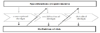
Fig 6: Relationship between physical and functional areas of risk process
The integration of security into the design consists of iterations of analysis and synthesis solutions reinforcing one another. As shown in Figure 6, the definition of risk is accompanied by a continuous development of new requirements. Therefore, each
type of interaction of the risk process is divided into two areas: physical and functional (Figure 6). Functional area meets the requirements of security and the physical realm to the defini- tion of risk. Indeed, both physical and functional views are from the correspondence between the design process and the risk. Since the design process consists of six phases (denoted Pi, i = 1 .. 6), the risk of the process also consists of six phases we call contexts (denoted Ci, i = 1 .. 6) ( Figure 7). Next the difference inherent characteristics of these two processes (con- cepts against knowledge), this correspondence is not done directly. The mapping can be one-to one, one-to-many or many-to-one (Figure 7).
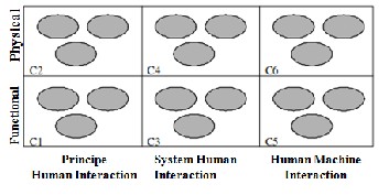
Fig 7: Process of risk in six contexts
This section is dedicated to explain the process which helped build and establish typologies of contexts risk process [3][4].
Each compound level of interaction is a functional area and a physical area.
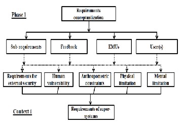
4.1. Context 1 (C1): Security requirements for super- systems
We define the super-systems as elements of the operating en- vironment. These can be defined as the set of physical, human, economic components ... in relation to the industrial system in a given life cycle situation.
This context expresses the security requirements from the op- erating environment of the industrial system.
These requirements are derived from the risks disclosed in the past (the feedback) by the use of the industrial system or simi- lar industrial system. From the perspective of the design in the respective phase (P1), the industrial system is essentially de- fined by technical-functional requirements, constraints, and the characteristics of a use environment. This context allows to complete these requirements by expressing requirements risks related to the context of use and offset through the design of the industrial system. These requirements must be possible the more detached expression highlighting the solution or EMUs involved. Then, they are integrated into the design specifica- tion either as a requirement or functional as a constraint. When it comes to consider specific actions; such as:
Prevent related accidents reversal of the machine; in this case the security requirement is specified and corresponds to a functional requirement. However, in situations where the de- sign can not exceed a certain limit, the security is then consid-
IJSER © 2014 http://www.ijser.org
International Journal of Scientific & Engineering Research, Volume 5, Issue 7, July-2014 1078
ISSN 2229-5518
ered as a constraint.
As explained above, in any design industrial system there are two types of requirements: external requirements and internal requirements. External requirements are specific for any de- sign. Internal requirements are those relating to a given de- sign; they are the result of decisions taken. Similarly, we be- lieve that the security requirements are scalable with the de- sign. Some external (EMUs requirements and constraints on human characteristics) from other analyzes of risk decisions and thus correspond to internal requirements. Unlike the technical requirements, the security requirements are mainly identified during the design.
Characteristic actions of this context are:
• Identify the elements of the operating environment, identify the hazards associated with them, identify
the nature and severity;
• Break the hazards taking into account the phases of life involved and potentially dangerous events;
• Describe the resources, the mode of operation of the
EMU affected and modes of user intervention;
• Define the spatial and temporal constraints of the user on the operating environment;
• Formulate security requirement. We propose the fol-
lowing a security requirement formulation: Minimize (hazard) of (EMUi) compared to (characteristic as- signed by the user);
• Specify the requirement depending on the level and nature of the hazard and characteristics or EMUs con- cerned;
• Giving orders of priorities different requirements de-
pending on their severity.Indeed, the type of this con- text is derived from the nature of the information in phase 1 of the design. We considered that there is a correspondence between phase 1 and Context 1. Ty- pology of information from this correspondence is shown in Figure 8.
The following is a non exhaustive list of the types of objects that form this context:
• Requirements external security - Functional require- ments for elements of the environment of use;
• Vulnerability man - effects that energy on human be- ings;
• Stress anthropometric - constraints on the dimen- sions of the human body of the population concerned;
• Physical Limitation - constraints on postures, move- ments and physical forces of the human population concerned;
• Mental Limitation - level of education, experience, age and number of concurrent tasks allowed for the population considered. We do not take into account organizational factors.
Fig 8: Mapping Phase 1/1 Context
4.2. Context 2 (C2): Risk of accidents
This context considers risks related accidents hazards from a part of the field and secondly, the nature of the principle of the selected physical solution. As already defined, the hazard is a potential source of injury. In this context, we consider that a hazard is always generated by an energy and nature of the risk resulting source is dependent on the nature of the energy considered. In the case of designing a new industrial system, the nature of the risk associated with the type of energy used can be derived from standardization (such as the standard [5]). The hazards are identified, risks for each phenomenon are evaluated. The risk assessment is made based on the intensity of the energy contained in a solution principle. Considering the technical performance criteria, the principle of recognizing the solution is less likely selected.
At the stage of conceptual design, we are interested in study- ing the energy used in the principles of the solutions adopted. Of course, the value of the energy in human interaction can be modified at the architectural or detailed design, but we believe that less energy level is high in the solution is more secure. Indeed, changes qu'entraînent the following steps to "hide" this energy but do not eliminate it. In addition, the effects of risks associated with choosing the design decreases gradually as we advance in the design of the industrial system, as we have more information on the industrial system we have less decisions take less and the effects of our choices are important.
Moreover, the choices made in advanced stages of the design process will reduce or even amplify undesired effects. It is therefore necessary to keep a trace on the choices made at each level and to study the possible events.
Shares characteristics of this context:
• Identify and analyze energy constituting the physical principle of the solution
• Determine the nature of the risk, and evaluate the
possible effects of gravity.
IJSER © 2014 http://www.ijser.org
International Journal of Scientific & Engineering Research, Volume 5, Issue 7, July-2014 1079
ISSN 2229-5518
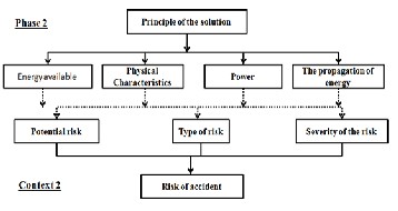
Fig 9: Mapping Phase 2 / Context 2
In effect the same as for Examples 1, the Examples of this type is deduced from the correspondence that exists between the phase 2 and the context 2. Information from the correspond- ence are shown in Figure 9.
Below is a list of the types of objects that form this context:
• Potential risk - risk relating to the physical solution;
• Type of risk - nature of the risk relating to the physi- cal solution;
• Severity risk - the severity of the risk relating to the physical solution.
4.3. Context 3 (C3): System Security Requirements
We understand the system structure of the industrial system based on the principles of scheduling solutions. This context describes the security requirements that will guide the choice of this structure. From the perspective of the human, the sys- tem will cause a certain work procedure for the operation of the industrial system. A procedure can be defined as a set of activities that are linked together in chronological order to achieve a goal in the context of a labor organization. The pro- cedure from the perspective of human activity is the organiza- tion and succession in time and space of an individual task or sequence of all user actions within a system working.
Procedure is to determine Who's What, Where, When, How, How, and Why. What comes first, to determine the allocation of functions between the user and the industrial system, in- formation that comes directly from the principle of solution retained in the P2 phase.
Then, it comes to define the nature of the activity of the user. Space constraints and the nature of the activity, we can deduce the possible locations of the user and the frequency response. All these data are interconnected by a primary requirement reflecting the ultimate goal of the user.
Allocation of functions - the process of deciding how the sys- tem functions will be performed by men, equipment and / or hardware and / or software [1].
Thus, this context will reduce the range of possibilities for the
structural arrangement of the principles of solutions solutions, depending on possible and acceptable user positions, as well as anthropometric data. In addition, depending on the nature of human activity, maximum effort required should be taken into account, which will provide input for the design and choice of materials data. Data for the human that are external to the design constraints enumerated starting the process. They can be deduced from feedback or internal to an organiza- tion knowledge. A first objective of this context is to imple- ment the requirements of spatial and temporal separation of the user hazardous areas where they exist.
In addition to these purely adaptive requirements, we can have security functional requirements. The latter are the sub- ject of the operations analysis of physical design choices and correspond to internal requirements.
Finally, the type of objects of this context is derived from the nature of the correspondence between phase 3 and context 3. The information from this correspondence are shown in Fig- ure 10.
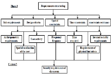
Fig 10: Mapping Phase 3/3 Context
Below is a list of the types of objects that form this context:
User activity: organization in time and space of user tasks; Meet internal security requirements and the solution from the previous step of the design;
• Time: Estimated time to complete a task;
• Frequency response: Estimated frequency of a task;
• Space Location: user's position in space;
• Requirements physical limitations: constraints speci- fied at the end of the design choices and physical data relating to the human;
• anthropometric requirements: constraints specified at the end of the choice of design and actions on the human body.
4.4. Context 4 (C4): Ergonomic Hazards
This context will be to describe the risks relating to the viola-
IJSER © 2014 http://www.ijser.org
International Journal of Scientific & Engineering Research, Volume 5, Issue 7, July-2014 1080
ISSN 2229-5518
tion of human ergonomic point of view limitations. The archi- tecture of the industrial system is designed in Phase 4, this context allows a description of the hazardous areas, the loca- tion of the use and characterization of the tasks assigned. Haz- ardous area is geometric space, inside and / or around ma- chinery in which a person may be exposed to a hazard [5]. In principle, this is a space that defines the hazard. Hazardous area may be present continuously or appear unexpectedly after a dangerous event. Thus, at this stage of the design a hazard has an effect when (1) the task given to it is not ergo- nomic or; when (2) the user is in a particular area where the energy is dissipated in time the danger zone. In this context, the risks are then of two types: those internal to that step and correspond to ergonomic hazards and external ones at this stage but internal to the design. These correspond to the risk of accidents not resolved at the stage of conceptual design.
Ergonomic risks are characterized by a task. This task defines the spatial location of the user, posture, movement, physical and mental efforts. Hazardous areas are defined by a shape, a location, a volume and gravity, which is associated with a hazard. We consider that there are two types of hazardous areas; those from the field and those on the solution. The first is the external hazardous areas will generate a first field limi- tation of the solution. These areas are considered existing and solution seeking to offset their effects. The second type of haz- ardous areas are those generated by the decisions taken dur- ing the design and are internal to the industrial system. If there are multiple risks, they should be classified according to their potential effects on humans. Finally, in this context it is to study the compatibility of the backbone of the solution with that of the user.
Taking into account the technical performance criteria, struc- tural arrangement admitting the least risk is selected. Of course, the level of risk in human interaction can be modified during the detailed design. However, we believe that less ar- chitecture allows dangerous confrontation zone / man is more secure. The changes caused by the steps will result in the addi- tion of components and complication of the solution. The ef- fects of the risks associated with choosing the design to de- crease gradually as we advance in the design of the industrial system, as we have more information on the industrial system was less freedom in decisions and under the effects of our choices are important.
Shares characteristics of this context:
• Locate the user for a given task;
• Locate hazardous areas for a given configuration;
• Confronting the skeleton of the solution with that of the man for the job in question;
• Identify the affected members of the human and the postures, movements and effort required;
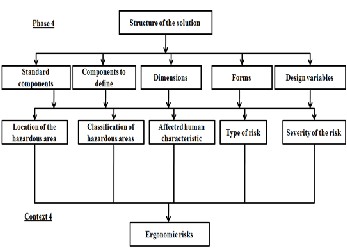
Sort hazardous areas points of view into account the severity of the energy level, the vulnerability of the affected limb, the difficulty of the task, the time spent and frequency of interven- tion. Figure 11 shows the type of objects in the context 4.
Fig 11: Mapping Phase 4/4 Context
Below is a list of the types of objects that form this context:
• Type of risk - nature of the risk relating to the physi- cal solution;
• Severity risk - the severity of the risk relating to the
physical solution.
• Feature affected man - parameters involved in the task;
• Location of the danger zone - position in space of the
energy field;
• Classification of hazardous areas - danger level of the dangerous zone
4.5. Context 5 (C5): Security requirements for subsys- tems
We define subsystems system components that will allow the finishing of the industrial system and will intervene at the stage of detailed design. This context describes the security requirements that will guide the choice of secondary compo- nents of the solution. From the point of view of humans, these components are at the origin of the system, it is they who are the man-machine interface. The man-machine interface de- scribed the interaction between the user and the industrial system in use. This interface is directly related to the nature of human activity.
Thus, this context will reduce the range of possible solutions for the choice of the latest components as required characteris- tics of the human. A first objective of this context is to estab- lish requirements that will allow the choice of accepting the latest components less risk.
At this stage, security is expressed mainly in external forms of functional requirements in the step of the detailed design, but in the internal solution. The requirements are mainly from previous stages and correspond to non-solved problems. Gen- erally, the effects of demand from this step are minimal com- pared to the overall security of the industrial system.
Finally, the types of context objects that is deduced from the nature of the correspondence between the stage 5 and the con-
IJSER © 2014 http://www.ijser.org
International Journal of Scientific & Engineering Research, Volume 5, Issue 7, July-2014 1081
ISSN 2229-5518
text 5. Information from the correspondence are shown in Fig- ure 11.
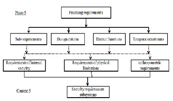
Fig 12: Mapping Phase 5/5 Context
Below is a list of the types of requirements that form the con- text:
• Requirements internal security requirements and the
solution from the previous step of the design;
• Requirements physical limitations: constraints speci- fied at the end of the design choices and physical data relating to the human;
• Anthropometric requirements: constraints specified at the end of the choice of design and actions on the human body.
4.6. Context 6 (C6): Residual Risks
We define the residual risks as risks relating to the design but whose effects are minimal compared to the risks related to other choices in the design. At this stage of detailed design, risks related to natural selection can produce either accidents or ergonomic problems.
The components of the industrial system, and hence their ar- chitecture, is designed or selected in step 6, this allows a con- text description of hazards related to the components.
These phenomena are related firstly to the structure of the component and also to the energy that is defined by and con- tains hazardous areas. These zones are defined by a shape, a location, a volume and gravity. This type of risk is related to the decisions taken during the design and are internal to the industrial system. Phenomena are identified using the feed- back obtained from the use of its components in other designs. In the case of designing a new component, the hazards can be deduced from the study of potential interactions between the component and the skeleton of the human skeleton.
Shares characteristics of this context:
• Locate hazardous areas for a given component;
• Confronting the skeleton of the component involved with the man for / position (s) can (s) part;
• Identify the importance of the affected human charac-
teristic.
The following is a non exhaustive list of the types of objects that form this context (Figure 12):
• Type of risk - nature of the risk relating to the physi- cal solution;
• Severity risk - the severity of the risk relating to the
physical solution.
• Feature affected man - parameters involved in the task;
• Location of the danger zone - position in space of the
energy field;
Classification of hazardous areas - level of risk the danger zone considered
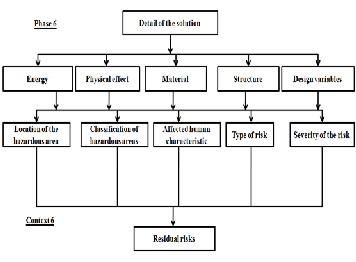
Fig 13: Mapping Phase 6/6 Context
If all risks to health have been addressed and resolved at each stage of design, there will be no interest to analyze the risks according to conventional methods.
In all these contexts, the security issue is considered resolved in the corresponding phase.
5. CONCLUSION
We presented the model that we propose for the integration of security at the earliest with the design of the industrial system. Then we presented the model properties. The latter consists of a systematic integration of design and axiomatic design. It considers two processes, process design and process risk, evolving simultaneously and affect each other mutually. Final- ly, we detailed the contents of both the design process and risk.
REFERENCES
[1] AFNOR (2009). NF EN 614-1+A1Sécurité des machines - Principes ergonomiques de conception: Terminologie et principes généraux. Editée par Association Française de NORmalisation (AFNOR).
[2] Ge, P., Lu, S. C.-Y., Suh, N. (2002). An axiomatic approach for target cascading of parametric design of engineering systems. Annals of the CIRP, 51, 111-114.
[3] Ghemraoui, R., Mathieu, L., Tricot, N., (2009a). Systematic Human- Security Analysis Approach based on Axiomatic design Principles. Fifth
IJSER © 2014 http://www.ijser.org
International Journal of Scientific & Engineering Research, Volume 5, Issue 7, July-2014 1082
ISSN 2229-5518
International Conference on Axiomatic Design, Portugal, March.
[4] Ghemraoui, R., Mathieu, L., Tricot, N., (2009b). Méthode d’intégration systématique des facteurs humains à toutes les phases de la conception.
11ème Colloque National AIP Primeca, Laplagne, Avril.
[5] ISO (2007). ISO 14121-1, Sécurité des machines - Appréciation du risque - Partie I Principes. Editée par International Standards Organization (ISO).
[6] Pahl&Beitz (2007). Pahl, G., Beitz, W., Feldhusen, J., Grote, K.-H, Engi- neering design: A systematic approach. 3 edition Berlin: Springer-Verlag.
[7] Suh, N. (1990). The principles of design. Oxford University press.
[8] Suh, N. (2001). Axiomatic Design: Advances and Applications, Oxford
University Press.
IJSER © 2014 http://www.ijser.org