International Journal of Scientific & Engineering Research, Volume 6, Issue 4, April-2015 1061
ISSN 2229-5518
Connectivity Restoration in WSN Using Minimal
Topology Changes
M.Sureshkumar, P.Umasuruthi, P.Ushapreethi
Abstract—In wireless sensor networks, the efficiency mainly depends on the network connectivity among the nodes as well as coverage of the monitoring area. Failure of nodes due to technical faults or power exhaustion may disturb the existing connectivity by partitioning the network. Node replacement mechanisms are used based on the controlled mobility with the handling of node failures. The idea is to identify the critical nodes which cause the network partitioning and to designate the failure handlers for them suddenly after the network deployment of sensor nodes. To increase the network coverage by identifying the coverage holes and move the mobile nodes to a certain distance. The connectivity restoration process is done using the failure handler with identified movement distance. The effectiveness of the proposed approaches will be validated through simulation experiments.
Index Terms— Connectivity, Coverage holes, Failure handling, Minimal Topology changes, Network Coverage, Nodefailure, Relocation process.
1 INTRODUCTION
—————————— ——————————
WIRELESS Sensor Networks consist of small sensor sor nodes deployed randomly over an area to monitor the environment or detect intrusion. The connec-
tivity of the network and the coverage provided by the network is very crucial for the effectiveness. Sensor nodes are equipped with detectors for intrusion, sensing the changes in temperature, humidity, chemicals, or any other characteristic of the environment that needs to be moni- tored. The environment is constantly observed, consoli- dated, and sent to a monitor or Base Station (BS). Data transmission from the sensors to the BS can be periodic, event-triggered, or in response to a query from the BS. While each sensor node has limited computation capabili- ties and usually non -rechargeable battery power, the col- laboration among thousands of sensors deployed in a re- gion makes sensor networks a powerful system for obser- vation of the environment. Many of the important applica- tions of sensor networks demand autonomous mobility for the sensor nodes. Various types of mobility have been con- sidered for the mobile node [4]. These can be broadly clas- sified as random, predictable or controlled.
In the predictable mobility the mobile element is mounted on a bus like vehicle. The sensor nodes learn when the vehicle comes near them, and wake up accord- ingly to transfer their data. In the controlled mobility all the sensors can move on demand in addition to their sens- ing capabilities. This work has been done under the para- digm of controlled mobility.
Connectivity in the network is lost due to network par- titioning, where partitioning of network is caused by the failure of a node which is serving as a cut-vertex (i.e., a gateway for multiple nodes). Each node should determine whether it is a cut-vertex or not, in advance. The cut-vertex is determined by cut-vertex determination algorithm. In this algorithm the network graph is converted into depth first spanning tree.
One such cut vertex nodes are identified; each node des- ignates the appropriate neighbor to handle its failure. The designated node picks a node, called dominatee, whose absence does not lead to any partitioning of the network. This is achieved by utilizing the Connected Dominating Set (CDS) of the whole network. The CDS algorithm iden- tifies the dominating elements called dominators (an ele- ment of CDS) and dominatees (1-hop away from a domi- nator). The cut vertex determination and the failure han- dler detection processes are done initially when a sensor network is deployed.
The failure handling process is a dynamic process which has been held after the failure occurrence. At the time of these processes, the assumption is that only one node fails at a time and no other node fails until the con- nectivity is restored. The failure handling process is achieved by the movement of every node in the failure handling set to their feasible points determined by the MTC. To avoid the energy loss of a particular node served as failure handler every node in the failure handling set participates in the failure handling process. The migration of set of nodes for reconfiguration of network would cause coverage holes in terms of sensing modalities. These cov- erage holes have to be minimized to improve the efficiency of the network. To reduce the coverage gaps, the failure handler is placed in the surrounding of the failed node without affecting the connectivity. The technique is named as Minimal Topology Changes (MTC). The location of the nodes in the failure handling set is identified using MTC.
This technique reduces the Total Movement distance of all the Nodes (TMN) and increases the total coverage area.
IJSER © 2015 http://www.ijser.org
International Journal of Scientific & Engineering Research, Volume 6, Issue 4, April-2015 1062
ISSN 2229-5518
2 RELATED WORK
In Wireless Sensor Networks, mobility of a sink may provide an energy efficient way for data Collection. Node mobility has been exploited in wireless networks in order to improve various performance metrics such as network lifetime, throughput, coverage, and connectivity. Two types of mobility were considered in these efforts: inherent and controlled mobility. Inherent mobility can be further classified as random and predictable depending on the travel path. Controlled mobility of the internal nodes with- in the WSN has mostly been exploited to improve the net- work lifetime and coverage. In this case, mobile nodes are used as carriers to relay data from sources to the destina- tion [4].
The Dai’s algorithm [5] also strives to restore the connec- tivity when a cut-vertex node fails using cascading move- ment. But it does not provide a mechanism to detect cut- vertices. As mentioned in [6], the communication range (Rc) and sensing range (Rs) of each sensor can be controlled or adjusted by itself so that coverage and connectivity can be guaranteed. The main objective of coverage mainte- nance is to compensate the loss of coverage with minimum expenditure of energy. Dynamic Coverage Maintenance (DCM) schemes exploit the limited mobility of the sensor nodes. The basic vector construction method is keyed in
DFS is used for finding the cut-vertex, then the PADRA is referred as PADRA+. But in this work the coverage holes are introduced in the network after the cascaded move- ment for connectivity restoration.
From the literature survey, it is observed that most of the re- searches are related to either the connectivity maintenance of the network or the initial deployment strategy to improve the cover-
age. The improvement of the coverage area after any modifica-
tion in the network has not been discussed largely in the litera- ture. Hence, in this work both the connectivity restoration tech- nique and coverage improvement technique are proposed. The reduction in coverage area due to connectivity restoration is min- imized by MTC.
3 PROBLEM DEFINITION
The assumption is that the nodes (i.e., sensors) are ran- domly deployed in an area of interest and form a connect- ed network. The mobility capability is only exploited whenever needed. The nodes in such networks have a lim- ited energy supply. The radio range, denoted by r, of a node refers to the maximum Euclidean distance that its radio can reach. For all the nodes r is assumed to be con- stant. The Euclidean distance formula is given by,
[7]. The connectivity failures are not considered in this work and mobility of the sensor nodes is limited.
In CCAP proposed in [12] the coverage of the actor
r = ∑
i =0
∑
j =1
((xi-xj)2 +( yi-yj)2 ) (1/2)
nodes are maximized with connected interactive topology. But the coverage area reduction due to node failure is not considered. COCOLA [13] deal with the connectivity resto- ration using mobile nodes. It fixes extra nodes in the net- work for repositioning of failure nodes. DARA [14] is also deals with restoration of connectivity when a cut-vertex fails.
It does not find the cut-vertex and just assumed that the network details are available in the node itself, which re- quire the knowledge of the whole network topology. The dominators and dominatees are used in CDS formulation. This approach eliminates the concept of information gath- ering at each node, which may require the knowledge of the whole topology. The key concepts of CDS formation is discussed in [2]. The main advantage of connected domi- nating set is that it centralizes the whole network into small connected dominating set sub network, so that network topological changes do not affect this sub network. The reduced CDS is determined by pruning the current CDS by the process named marking process [3]. The reduced CDS is efficient than CDS.
Single and Multiple Node Failure handling are given in PADRA and MPADRA algorithms specified in [1]. PADRA achieves optimized recovery of a node failure by preplan- ning the failure handling process. These algorithms use CDS and cascaded movement idea together in order to re- store the failure of cut-vertices. In case of a failure, the clos- est dominatee determined using CDS will start a cascaded movement toward the location of the failed node. If local

Where xi , xj, yi and yj are the x and y position of the nodes on the grid. Sensing range for each node, on the other
hand, is assumed to be 2r. The energy of each node is fixed initially. The energy is reduced for a particular node if the energy becomes zero, the node is assumed to be failed. An- other assumption is that there is no obstacle on the path of a moving node and the nodes can reach their exact loca- tions by maintaining a constant speed.
• The Maximum Movement distance of all Individu- al nodes (MMI):
max i∈s M i
The maximum distance moved by an individual
node for a particular purpose.
• Total Movement distance of all the Nodes (TMN):
∑ M i
Ti∈hSe Total Movement distance of all the Nodes is
the summation of all MMIs.
Where, S denotes the set of nodes in the network and Mi
denotes the total movement distance for a particular node.
4 MINIMALTOPOLOGY CHANGES
4.1 Connected Dominating Set (CDS) Computation
The dominators and the dominatees are calculated by finding Neighbor Node List (NNL), Boundary Node List (BNL) and inner node list (INL). The NNL is determined by transmission range of the nodes. If the distance between two nodes is less than the addition of the radii then they
IJSER © 2015 http://www.ijser.org
International Journal of Scientific & Engineering Research, Volume 6, Issue 4, April-2015 1063
ISSN 2229-5518
are said to be neighbors. Neighbors of every node are stored in appropriate NNL. If a node has only one element in its neighbor node list that node is inserted in BNL. Oth- ers are inserted in INL. The calculated dominators are stored in the list CDS. The direct neighbors of dominator nodes are taken as dominatees. In most cases the domi- natees are selected as failure handler. In some critical situa- tion, the dominator is taken as a failure handler.
4.2 Cut-vertex Determination Algorithm
A cut vertex is defined as a sensor node whose removal breaks network connectivity. The cut vertices are deter- mined by the cut vertex determination algorithm. The net- work is represented as a graph. The fig 1.a shows the graph and Fig 1.b shows the spanning tree of graph in Fig 1.a the depth first search is done for the spanning tree of the graph. Edge (v,w) is the path between two nodes v and w. where v is the parent and w is the child in the spanning tree.
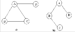
Fig.1 a. Simple graph b. Spanning tree for Fig 1.a.
1. The root (A) of the tree is visited first and marked. Then B is visited from A and marked. where A is v andisw.
2. When the edge (v,w) is considered, if w is unmarked, or, if v is unmarked, the edge is known as tree edge.
The tree edges are denoted as normal lines in Fig 1.b
3. When the edge (v,w) is considered, if w is already marked, and when edge (w,v) is considered, if v is already marked, the edge is known as back edge (i,e) the edge is not a part of the tree. The back edge is denoted as dashed lines in Fig1.b.
4) The cut-vertex is determined by doing the preorder traversal on the depth first spanning tree.
5) The numbers correspond to the order in which a depth search visits the vertices are referred as preorder number (Num(v)) is determined.
6) Then for each vertex v in the depth first spanning tree, the lowest numbered vertex (Low(v)), that is reachable from v by taking zero or more tree edges and then one back edge (in that order) is calculated. Low(v) is minimum of
a. Num(v)
b. Low(w) among all tree edges (v,w)
c. Num(v) among all back edges (w,v)
7) u is an articulation point (cut-vertex) iff u has a child w such that Low(w) >= Num(v) provided u is not a root.
4.3 Recovery Process
The cascaded movement is used from the dominatee to the failed node in order to maintain battery power loss on an individual node. The dotted line shows the direct re- placement path. It results in quick energy loss for node F. In the cascaded movement node F replaces node D and node D replaces node A. The TMN can be reduced by fix- ing the position of the failure handler D in the nearest posi- tion of the cut-vertex A, not in the exact position of A. The nearest position is known as ‘Minimum Movement Point’ shown in Fig 2. It is calculated by the following steps.
a) A position is fixed on the path between the failure handler and the cut-vertex at the distance α metres from the cut-vertex. (α is an integer, 0<α≤10, Initially the maxi- mum value is fixed for α).
b) Then the Failure Handler is moved to the calculated position.
c) The neighbors of the Failure Handler are calculated from the new position.
d) If all neighbors of the cut-vertex are visited by the
Failure Handler from the new position then the α value is
fixed and the position of the Failure Handler is stored. Otherwise the α value is reduced and the neighbor check-
ing is done until all nodes of the cut-vertex are visited from the new point.
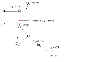
Fig.2 Graph having cut-vertices along with failure handlers
So the connectivity is maintained. In the same way the position of each dominatee is fixed in the surrounding of the next node in the failure handling path without affecting the connectivity.
IJSER © 2015 http://www.ijser.org
International Journal of Scientific & Engineering Research, Volume 6, Issue 4, April-2015 1064
ISSN 2229-5518
5 PERFORMANCE EVALUATION
The performance evaluation of MTC algorithms are ana- lysed in this section. The algorithms are evaluated in terms of mobility distance and total coverage area.
5.1 Simulation Setup
The proposed algorithms are simulated using ns-2.34 for different number of nodes that are deployed randomly over 500m × 500m. The number of deployed nodes varies from 10 to 40. In the simulation the TwoRayGround propa- gation model is taken for Radio Propagation and omni- directional antenna is considered for packet transmission. The IEEE 802.15.4 MAC is considered for the channel ac- cess mechanism.
For each sensor node, a fixed amount of 100J reserved energy is assumed. The sensing range of each sensor node is 80m with communication range is twice of the sensing range, i.e. Rc= 2Rs and a homogenous network environ- ment is considered.
6 CONCLUSION AND FUTURE WORK
The cut-vertices and CDS are determined using Cut- vertex Determination Algorithm and CDS algorithm re- spectively. The dominators and the dominatees are used in the connectivity restoration process. Basically, if a node finds out that it is a cut-vertex, one of its neighbors is dele- gated to perform failure recovery on behalf of that node. The replacement position is determined within the trans- mission range of the failed node without affecting the con- nectivity of the network. The failure recovery is done by determining the failure handling set and replacing the nodes in the failure handling set with the positions calcu- lated using MTC. The movement is shared among the nodes in the failure handling set to avoid the energy loss of the failure handler. The total coverage of the network area is increased up to 5 percent for 40 nodes compare to exist- ing techniques. The total mobility distance of the nodes due to connectivity restoration is reduced by 20m. In future, this problem can be extended to multiple node failure problems for a larger set of nodes.
vol. 15, no. Oct. 2004.
[4] Somasundara A.., Ramamoorthy A.., and Srivastava M., “Mobile Element Scheduling for with Dynamic Deadlines”, In the proceed- ings of IEEE transactions on mobile computing, vol. 6, no. 4, Apr.
2007.
[5] Abbasi A., Akkaya K., and Younis M., “A Distributed Connectivity Restoration Algorithm in Wireless Sensor and Actor Networks,” In the Proceedings of IEEE Conference on Local Computer Networks (LCN ’07), Oct. 2007.
[6] Wang G., Cao G., Porta T.L, and Zhang W., “Sensor Relocation in
Mobile Sensor Networks,” In the Proceedings on INFOCOM, Mar.
2005.
[7] Sekhar A, Manoj S., and Murthy S. R., “Dynamic Coverage Mainte- nance Algorithms for Sensor Networks with Limited Mobility”, In the proceedings of IEEE International Conference on Pervasive Computing and Communications, Mar. 2005.
[8] Prasan Kumar Sahoo, Jang-Zern Tsai, Hong-Lin Ke, “Vector Method based Coverage Hole Recovery in Wireless Sensor Networks”, In the proceedings of National Science Council of Taiwan, NSC 97-
2218-E-008-001.
[9] Li J.-S., Kao H.-C., “Distributed K-coverage self-location estimation scheme based on Voronoi diagram”, In the proceedings of IET Communications, Apr. 2009.
[10] Wojciech Kocjan Piotr Beltowski, “Tcl 8.5 Network Programming”, Packt
Publishing Ltd., UK. ISBN 978-1-849510-96-7, July 2010
[11] D. Wang, B. Xie and D. P. Agrawal, “Coverage and lifetime optimi- zationof wireless sensor networks with gaussian distribution”, IEEE Transactions on Mobile Computing, vol. 7(12), pp. 1444-1458, 2008.
[12] K. Akkaya and M. Younis, “Coverage-Aware and Connectivity
Constrained Actor Positioning in Wireless Sensor and Actor Net- works,” In the Proceedings of IEEE International Performance, Computing and Communication Conference (IPCCC ’07), Apr. 2007.
[13] K. Akkaya and M. Younis, “Coverage and Latency Aware Actor Placement Mechanisms in Wireless Sensor and Actor Networks,” International J. Sensor Networks, vol. 3, no. 3, pp. 152-164, May
2008.
[14] A. Abbasi, K. Akkaya, and M. Younis, “A Distributed Connectivity Restoration Algorithm in Wireless Sensor and Actor Networks”, In the Proceedings of IEEE Conference Local Computer Networks (LCN ’07), Oct. 2007.
REFERENCES
[1] Kemal Akkaya, Fatih Senel, Aravind Thimmapuram, and Suleyman Uludag, “Distributed Recovery from Network Partitioning in Mov- able Sensor/Actor Networks via Controlled Mobility” In proceed- ings of IEEE transactions on computers, vol. 59, no. 2, Feb 2010.
[2] Wu J. and Li H., “On calculating connected dominating sets for efficient routing in ad hoc wireless networks”, In the Proceedings of
3rd International Workshop on Discrete Algorithms for Mobile
Computing and Communications, 1999
[3] Dai F. and Wu J., “An Extended Localized Algorithms for Connect- ed Dominating Set Formation in Ad Hoc Wireless Networks”, In the proceedings IEEE Transactions on Parallel and Distributed Systems,
IJSER © 2015 http://www.ijser.org