International Journal of Scientific & Engineering Research Volume 4, Issue 1, January-2013 1
ISSN 2229-5518
Congestion-Free Elevator Control Using
Microcontroller
Poorvi Behre, Viveka Nema, Bhupendra Badoniya
Abstract— this work introduces a new solution of elevat or controlling syst em which is based on micr ocontrollers. The purpose of this work is to design an effective elevator control system, which can be reprogram m ed in a fashion to minimize the congestion on a particular lane by directing the lift on a particular floor using time managem ent schem e. Present scope of the project is to provide an automatic congestion control and hence found its im port ance in various fields of applications. By the use of such design complexity of the system has been simplified. Control softwar e was developed in C program ming language, whereby the new system capacities could be dem onstrated.
Index Terms— Elevator control, micro-controller, congestion free.
—————————— ——————————
ift or elevator, is a transport device that is very common to us nowadays. We use it every day to move goods or peoples vertically in a high building such as shopping centre, working office, hotel and many more. It is a very useful device that moves people to the desired floor in the
shortest time.
This work documents the findings and results of a research on
a microcontroller based lift control system. In this project,
AT82C51 microcontroller is used as the primary controller. Besides, it is consist of various inputs and outputs circuits together with a lift model. The AT82C51microcontroller is used to coordinate the functions of various hardware circuitries. Service request circuit and sensors are used as input. Stepper motor driver circuit, DC motor circuit, seven- segment display, optocouplers, buzzers and various types of LED (light emitting diodes) displays are used as output.
The lift model was constructed to simulate an actual lift in the real life. It can be counted as the output hardware of the system. The software for the system was too designed according to the real lift traffic management algorithm. The combination of the hardware and software perform the simulate function of a basic lift system.
In this project, lift control system is going to be produce by using microcontroller. Thus, the main objectives for this project is to design and construct a microcontroller based lift control system. There are some scopes which needed to achieve the objective for this project:
a) To design a lift control system by using microcontroller
AT89C51.
b) To design the program (software) for the overall system according to the real lift traffic management algorithm
c) To integrate the hardware and software in order to simulate
——————————————— —
Poorvi Behre is currently pursuing bachelor’s degree in electronics and communication.TieTech,India, E-mail: poorvibehre@gmail.com
Viveka Nema is currently pursuing bachelor’s degree in electronics and communication, TieTech,India
Bhupendra Badoniya is working as Asst. Prof. in Electronics and
Telecommunication Department, TieTech, India. E-mail:
the functions of a basic lift system.
d) To build a lift model to simulate the actual system.
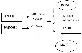
Fig 1: Block diagram of the elevator system
In this work, we show the basic elevator system with two floors. Although we show the concept with two floors shown in Fig 1, it is still possible to show this concept on multiple floors. Also, in this project, we will show two floors with 2 switches on each floor. The lift carries the person to each floor. Along with these 2 switches, we use separate switches for timed operation and priority for any floor. With the help of these switches, the lift automatically chooses a path when we press a start switch; the lift automatically starts and immediately responds to user input display which includes the path to resolve the congestion. Some options are provided for the user to make its selection to go to particular floor. Below is the list of choices user can make.
1. Ground floor input.
a) User can go to first floor.
b) User can go to second floor.
2. First floor input.
a) User can go to ground floor.
b) User can go to second floor.
3. Second floor input.
a) User can go to first floor.
b) User can go to ground floor.
For a given condition suppose second floor to ground floor is
of factor importance in a time schedule at 6 to 8. This condition is accepted by the system by the programmer as a switch entry and accordingly after two hours and three hours all the lift moving up and down use second to ground path to
IJSER © 2013 http://www.ijser.org
International Journal of Scientific & Engineering Research Volume 4, Issue 1, January-2013 2
ISSN 2229-5518
decrease the congestion. For timed operation we are going to use event difference, suppose this type of event has to happen after two hours so event is effective after two hours and continue its operations of a default 15 minutes.
TABLE 1
S.No | Component | Description |
1 | Step Down Transformer | 220 To 9 Volt AC- 750 mA |
2 | Diode | IN 4007 ( 2) |
3 | Capacitor | 1000MFD(2) 16 volt |
4 | Regulator | 7805( 3pin regulator) 1A |
5 | Resistor: Fixed | 470 Ohm.(3), 10 K Ohm (1),4,7 K (2) |
6 | Reed Sensor (10) | |
7 | Lcd | 2 BY 16 |
8 | Variable Resistor | 4. 7 K Ohm |
9 | Optocoupler | PC 817 (2) |
10 | NpnTransitor (2) | BC 548/547 |
11 | Pnp Transistor(2) | BC 558/557 |
12 | Dc Motor | Gear Slow Speed 9-12 volt-250 mA |
13 | Crystal Oscillator | 12 MHz |
14 | Disc Capacitor | 27 PF (2) |
15 | Atmel Microcontroller | 89C51 |
In this project work we will try to develop a two stories passenger lift or cargo lift using microcontroller AT89C51. This is a model of simple lift or elevator in which a building is assumed which has two floors:
There is a cabin of lift or elevator which will be moved up o down among different floors with the help of a motor. In this
project of lift or elevator a single motor is used which will move the cabin up or down. Thus we have to learn about the control of this motor which is responsible of lift cabin movement on right time in right direction.
There are two floors in the building, thus lift cabin has to moves between these floor, for floor detection and to generate the arrival of any floor, some sensor are used. The floor detection sensors are limit switches which could be proximity switches. The proximity switches are sensors which changes the stat of a signal when metallic piece comes near them. The Principles of operation of inductive proximity sensors used in PC control, microcontroller or microprocessor projects and automation systems are as a proximity sensor is a sensor able to detect the presence of nearby objects without any physical contact or in other words we can say that a proximity sensor often emits an electromagnetic or electrostatic field, or a beam of electromagnetic radiation and looks for changes in the field or return signal. The proximity sensors are the best for the detection of floor and could be used in this project. Thus, we will use three proximity sensors for three stories elevator project, one proximity sensor on each floor. These sensors have to be aligned with each other, such a way that, all sensors should be placed on equal distance from floor and these should be mounted to detect the bottom edge of lift cabin. By considering above precaution in the installation of sensors, lift cabin will stop on each floor correctly and doors of cabin and floor will be automatically aligned. Three signals will be generated from within the lift cabin: these could be push buttons and will be used to request the lift to go on desire floor. The lift cabin will have two push switches for this purpose, one for each floor.7-segment led indication of lift system circuit design. Three signals will be generated outside the lift cabin, one from each floor. Again, these would be push buttons and there purpose will be to call the lift on desired floor, if it is not currently present there. The status of lift will be indicated with the help of seven segment display. One seven segment display will be installed on each floor; which will tell the current location of the lift. Following display pattern could be visible on seven segment display of lift project:
0: It means lift or elevator is on floor # 0 which is ground floor.
1: It means lift or elevator is on floor # 1 which is first floor.
2: It means lift or elevator is on floor # 2 which is second floor. The seven segment circuit is separate from main controller circuit of lift. The power supply of master controller circuit, and three floor indicator circuits (LED seven segment display) will be separate and communication between these will be through optocouplers.
In this project we can use L817 or 4N35 optocouplers. Please note that the inputs of the master controller will also be connected to microcontroller 89C51 through optocouplers like L817. The circuit diagram of Elevator Lift control for two stories with microcontroller 89C51 is shown in Fig2.
IJSER © 2013 http://www.ijser.org
International Journal of Scientific & Engineering Research Volume 4, Issue 1, January-2013 3
ISSN 2229-5518
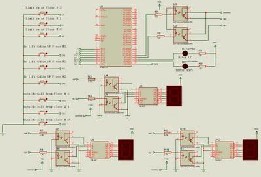
Fig 2: circuit diagram of lift control
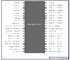
Fig 3: pin configuration of 89C51
In this project, we use the 8051 controller to interface all the inputs and outputs. In the input device, we use 10 sensors and one start switch. In output, we use one LCD as a display and one motor to move up-ward and down word. The brain inside the controller is to control all these inputs and outputs and perform perfectly. 8051 is basically an INTEL IC but now in these days it is available with many companies. We use ATMEL 89C51 series with advance feature than 8051. ATMEL
89C51 is a 40 pin controller with 128 bytes of ram and 4 k byte of ROM inside. Pin no. 40 of the controller is connected to the positive 5 volt power supply. We provide a 5 volt regulated power supply on this pin. Pin no 9 is the reset pin and this pin is connected to a capacitor and resistor network to provide an auto-reset option, when controller is wake-up. For manually reset, we connect one push to on switch in parallel with the capacitor to provide manual reset option. Pin no. 20 is connected to the ground pin. Pin no. 18 and 19 are connected to the external crystal to provide a constant oscillation to the circuit. Two capacitors are grounded from the crystal pins to provide stabilization. All the reed sensors are connected to port p1 and port p3. First floor parking sensors are connected to the p1.0, p1.1, p1.2, p1.3. These four sensors are related to the first floor sensor. Second floor sensors are p1.4, p1.5, p1.6, p1.7. First floor stoppage sensor is p3.2 and second floor stoppage sensor is p3.3. Start switch of this project is p3.0. On this start switch either we connect a start switch or we connect an infra red sensor. In the case of infra red sensor, when the
car enters the parking position, the lift senses automatically and starts.
Motor of the lift is connected to the p2.0 and p2.1. Output of these pins is connected to the optocoupler circuit. Here we use a pc 817 optocoupler to provide an electrical isolation between motor control circuit and micro controller. Output from the controller is connected to the cathode of infra red led through
470 ohm resistor. When controller is on, the infra red led is on due to negative output from the controller. When infra red LED inside the coupler is on then this light drive the internal phototransistor of the coupler. Output from the coupler is now connected to the H bridge circuit. In the H bridge circuit, we use four transistor circuits with one dc motor. In the H Bridge, we use a four transistor circuit. In this four transistor circuit, two transistors are NPN and two transistors are PNP. With the help of these four transistors, we control the direction of the motor. Not only we control the direction of motor but also, at the same time these transistors share the load of the motor directly.
Port p0 of the controller is connected to the LCD directly. Here
we use port p0 with the data pins of the ASCII code. LCD displays only the ASCII code. In the programming, we convert the digital code in to ASCII code by adding 30h in any binary number. So to provide a data in the LCD, we send these codes by the 8 data lines. These data lines from the controller are from the P0.0 to P0.7.
P2.5, P2.6, P2.7 is connected to the control pins of the LCD. On
this control pin, we select the command register, data register and the enable pin. We use the command and the data register pins to send the data and command separately. The interfacing of microcontroller with the LCD chip is shown below in the circuit diagram:
#include<reg51.h> //include reg51.h//inputs from limit switches on each floor
sbit limit_sw_f2 = P1^0; // active low sbit limit_sw_f1 = P1^1;
sbit limit_sw_f0 = P1^2;
// inputs from cabin for request to go on required floor
sbit goto_sw_f2 = P1^3; // active low
IJSER © 2013 http://www.ijser.org
International Journal of Scientific & Engineering Research Volume 4, Issue 1, January-2013 4
ISSN 2229-5518
sbit goto_sw_f1 = P1^4;
sbit goto_sw_f0 = P1^5;
// inputs from outside cabin to call lift on each floor
sbit call_sw_f2 = P1^6; // active low
sbit call_sw_f1 = P1^7;
sbit call_sw_f0 = P3^7;
// outputs for motor
sbitmotor_up = P3^5; // logic low will turn ON the motor for
Up
sbitmotor_down = P3^6; // logic low will turn ON the motor
for down
// output for display
sbit digit_0 = P3^3; // active high
sbit digit_1 = P3^4; // active high
unsigned char floor;
//void delay(void);
void main (void){
P1 = 0xff;
P3 = 0xf8;
floor =0;
// on powered up goto ground floor
while(limit_sw_f0){motor_down =0;motor_up=1;}
motor_down =1;motor_up=1;
digit_0=0;digit_1=0;
while(1){
if((floor==0)||(floor==1)){
if((!goto_sw_f2)||(!call_sw_f2)){
while(limit_sw_f2){
motor_down =1;motor_up=0;
if(!limit_sw_f1){digit_0=1;digit_1=0;floor=1;}
}
motor_down =1;motor_up=1;
digit_0=0;digit_1=1;floor=2;
}
if((!goto_sw_f1)||(!call_sw_f1)){
while(limit_sw_f1){
motor_down =1;motor_up=0;
}
motor_down =1;motor_up=1;
digit_0=1;digit_1=0;floor=1;
}
}
if((floor==2)||(floor==1)){ if((!goto_sw_f1)||(!call_sw_f1)){ while(limit_sw_f1){
motor_down =0;motor_up=1;
}
motor_down =1;motor_up=1;
digit_0=1;digit_1=0;floor=1;
}
if((!goto_sw_f0)||(!call_sw_f0)){
while(limit_sw_f0){
motor_down =0;motor_up=1;
if(!limit_sw_f1){digit_0=1;digit_1=0;floor=1;}
}
motor_down =1;motor_up=1;
digit_0=0;digit_1=0; floor=0;
}
}
}
This work is being started to develop a microcontroller based congestion free elevator control. A working is developed that replicates the real elevator system. The proposed scheme is implemented and testing of the algorithm (program) on the model is used to validate the efficiency on the microcontroller.
Present work is carried out using C coding in future this can be done using other programming languages.
Microcontroller can be replaced by Programmable
Logic Controller.
Control strategy can be governed using the fuzzy
logic technique.
Further scope in design, operator console board may
be used for display and keypad design
REFERENCES
[1] Department Of Measurement and Information Systems, "Microprocessor based elevator controlling system", version: FLV-V02.1, 1989 (Project report in Hungarian).
[2] .Microprocessors and Interfacing (Programming & Hardware)-Douglas
V.Hall.
[3] MaykePredco, Hand book of Microcontroller (MC GrawHill,co
,USA)1999.
[4] http://www.atm el.com
[5] http://www.elect ronics4u.com
[6] http://www.ttransenergic.co.au
IJSER © 2013 http://www.ijser.org