International Journal of Scientific & Engineering Research, Volume 4, Issue 6, June-2013 3038
ISSN 2229-5518
Computer-Based Frequency Drift Control of Multiple LASERs in Real-Time
Abstract— This research presents a LASER locking scheme that provides considerably much higher stabilization of LASER frequency in real-time environment. The scheme is implemented using LabVIEW Software in Real-time Operating System (RTOS). The scheme allows stability of the LASERs within the line-width of the respective transitions. Using this scheme, the Extended Cavity Diode LASERs (ECDL) are locked to a saturated absorption curve of a reference LASER automatically. The system can remain locked for several hours. The scheme also provides a human friendly interface and allows access to tune the LASER frequencies.
Index Terms— Data, Frequency Drift, Frequency Locking, Imaging System, LabVIEW, LASER, Real-Time Operating System (RTOS)
—————————— ——————————
RAPPING single atom is described as one of the most demanding experiments in atomic physics. Trapped and LASER-cooled ions are considered as most promising agents for the realization of an ion trap quantum computer [1],[2]. Ion trapping experiments require a number of LASERs operating at the required frequency to perform cooling and trapping of ions. The frequency of the cooling LASERs must be tuned very accurately relative to the transition frequencies of the trapped ions. The LASERs are frequency stabilized within the line-width of the respective transitions for efficient cooling and re-pumping requirement. In order to obtain flexibility and interactivity, the computer software-based graphical environment is developed using LabVIEW. The LabVIEW environment provides a robust control to the hardware used in frequency stabilization setups [3],[4],[5]. To ensure the deterministic behavior, the computer program is implemented on the Real-Time Operating System (RTOS) provided by National Instruments i.e. NI-RTOS. The key difference between RTOS and general computing operating systems (such as Windows, Linux, UNIX etc.) is the deterministic timing behavior which is the feature of RTOS. Deterministic timing means that the operating system consumes only known and expected amount of time. The RTOS operates in a controlled environment in which computer memory and processing power is limited. The RTOS controls the tasks execution on application software and provide their services within a strict time window to their users by running the tasks in a very timely and responsive way. The NI-RTOS installed computer (Target) used in our lab communicates with the personal computer (Host) via Ethernet network. The locking program runs on the target PC and its display and controls are monitored by using the host PC
which runs with a Windows Operating System (Win/OS).
————————————————
1 Institute of Physics, University of Sindh, Jamshoro, Pakistan
2 Department of Physics, Islamia University, Bahawalpur, Pakistan
3 Department of Physics, University of Sargodha, Sargodha, Pakistan
4 Department of Computer Science, University of Karachi, Karachi, Pakistan
Email: altaf_nizamani@yahoo.com, hussainsaleem@uok.edu.pk (Corresponding Author)
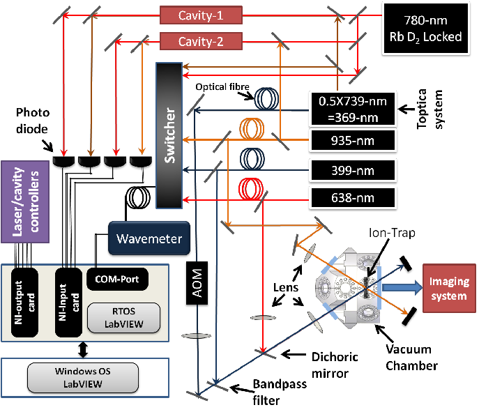
A schematic diagram of our LASER frequency stabilisation
setup is shown in Figure-1. There are three major parts of the scheme: (1) the stabilized LASER system, (2) the optical cavity and (3) computer controlled feedback based on synchronized scanning of the piezo-electric transducer (PZT) combined with data acquisition. Figure-1 also depict the LASER locking- scheme and alignment into the trap. The computer controlled program in LabVIEW real-time module simultaneously scans the cavities and generates error signal to control the drift in the LASER frequencies via feedback system.
To ionise Yb (Ytterbium) and excite its internal energy states in an ion trap experiment, 369-nm, 399-nm, 638-nm and
935-nm coherent light sources are required. The External Cavity Diode LASERs (ECDL) are in common use in ion trapping and LASER cooling experiments. This flexibility of the ECDL makes them a primary choice for LASER systems for the experiments. ECDL frequency and output power can be varied by varying the current and the temperature of the diode along with the grating angle. To provide the first stage of the photo-ionization process for Yb atom, light at 399-nm is used to resonantly excite it from the 1S0 --- 1P1 transition [6]. For the second stage, it is achieved by using light at 369-nm. It also cools the trapped ion immediately after ionization by exciting its 2S½ --- 2P½ dipole transition. The 369-nm light is generated by frequency doubling of light at 739-nm using a nonlinear crystal Lithium Triborate (LBO). The 739-nm light is generated by built-in ECDL setup. Light at 935-nm is used as a re-pump source to drive the 2D5/2 --- 3D[3/2]1/2 transition to prevent the ion being lost to the dark state 2D5/2 . The frequencies of the LASER diodes are strongly sensitive to temperature change, electric current and cavity length (acoustic oscillations). To avoid any drift in cooling LASER frequencies, it is necessary to lock the LASERs with a known frequency reference during the trapping and cooling experiments. Various electrical and optical methods have been experimented to improve the frequency stability of LASER diodes. The locking scheme in our lab is done by locking 739- nm and 935-nm LASERs to a passively stable reference cavity using an RF (Pound-Drever-Hall) lock.
IJSER © 2013 http://www.ijser.org
International Journal of Scientific & Engineering Research, Volume 4, Issue 6, June-2013 3039
ISSN 2229-5518
Fig-1: LASER locking-scheme and alignment into the trap. The computer control program in LabVIEW Real-Time module simultaneously scans the cavities and generates error signal to control the drift in the LASER frequencies.
When the absolute LASER frequency stabilization is required, it is normal to lock the frequency of the LASER to an atomic standard using saturated absorption spectroscopy. Those frequency references which utilise the natural atomic transition lines, are in common use in LASER locking schemes. In order to keep the reference LASER locked with known standard wavelength, in our lab, Rb D2 transition line with Γ~2π6 MHz is used as a frequency reference.
In order to provide a frequency reference, a 780-nm ECD LASER setup is constructed in the lab. The frequency of the
780-nm LASER is locked to one of the hyperfine atomic transitions of Rb. To access the hyperfine transition of Rb, a saturation absorption spectroscopy setup is constructed in lab [7],[8],[9].
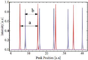
Two counter-propagating overlapping pump and probe LASER beams, with 1.3 mW and 0.1 mW power respectively are crossed through a Rb cell. Figure 2(a) shows the saturation peaks with a Doppler background spectrum of Rb87and Rb85 isotopes. The corresponding transitions are shown in Figure 2(b). The saturation peaks are obtained by scanning the LASER frequency around the resonance transition. By electronically differentiating the saturation peak signal using a Lock-in amplifier, a sharp zero crossing point at FWHM (full width at half-maximum) of the resonance corresponding to zero of the gradient is obtained. The feedback signal to stabilize the LASER around this zero crossing is then provided to the LASER controller using proportional integration (PI) controller. This locking scheme provides a stabilized frequency reference with an accuracy of less than 1MHz. This LASER is then used to lock the cooling LASERs by the transfer cavity lock method.
IJSER © 2013 http://www.ijser.org
International Journal of Scientific & Engineering Research, Volume 4, Issue 6, June-2013 3040
ISSN 2229-5518
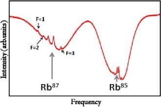
Fig-2(a): The saturation absorption spectroscopy signal obtained by scanning the LASER over the Rb87 and Rb85
There are two separate Fabry-Perot confocal cavities being used. A combined beam of stabilized 780-nm and 739-nm LASERs using a polarising beam splitter is aligned into one Fabry-Perot confocal cavity and 935-nm is combined with the
780-nm in the other cavity. In order to achieve the resonant peaks, the cavity is scanned at the speed of 50 to 70 Hz by applying a ramp voltage function to the piezo at the cavity. The output beam from the cavity is then split into its constituents using a second polarizing beam splitter and the intensities of two beams measured using photodiodes. The signal from the photodiodes is then read in computer controlled electronic analog to digital convertor (ADC) cards.
The absolute error on the wavemeter used in the lab is specified as ±60 MHz and its relative uncertainty is ±10 MHz. Therefore, the wavemeter can also be used to lock those LASERs where this level of accuracy is acceptable. Hence, the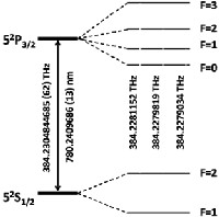
399-nm ionisation LASER and 638-nm re-pumping LASERs are locked directly to the wavemeter. To achieve this, a LabVIEW program running on the wavemeter computer sends the frequency/wavelength values of the LASERs which has to be locked, to the RTOS computer, via the COM-Ports of both computers.
Fig-3: The distance between the two reference LASERs (780-nm) peaks is denoted as a and the separation between unstable LASER (739-nm or
935-nm) peak and the reference LASER peak is denoted as b.
In order to provide long-term stabilization to the LASERs used in our lab, a computer-based multifunctional data acquisition system scans the LASER cavities and synchronously reads the cavities spectra of the multiple LASERs. By comparing peak positions relative to the stabilized Rb-locked 780-nm LASER, the computer generates the error signal in real-time to control the long-term drift of the LASERs. The voltage signals from the photodiodes are read through the National Instruments (NI) Data Acquisition Card PCI-6143 S-series DAQ shown in Figure-4, which we have configured accordingly keeping in view electronic signal parameters.
Fig-2(b): Hyperfine structure of Rb87 D
line
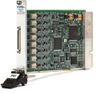
Fig-4: National Instruments (NI) Data Acquisition Card PCI-6143 S-series
DAQ, Input Read Card
IJSER © 2013 http://www.ijser.org
International Journal of Scientific & Engineering Research, Volume 4, Issue 6, June-2013 3041
ISSN 2229-5518
Wavemeter PC
COM Port
Connection
SYNCHRONIZED DATA ACQUISITION IN
Real-Time Operating
System (RTOS)
Data Transfer through
ETHERNET
Data From RTOS PC Separate the
SPECTRA Signal
Display SPECTRA
Find all the peak positions and Ratios
Generate Error Signal and
Feedback to LASERs
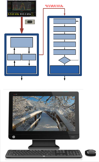
Software interface front panel of the LabVIEW program provides control boxes where the required wavelength can be typed-in. The program computes an error signal by comparing both the required and measured values. The calculated feedback is then sent to the LASER controller via the output card (PCI-6722).
We have successfully demonstrated a robust scheme for LASER frequency locking based on the real-time LabVIEW module implemented using commercially available NI-cards. The scheme provides a fast control over the LASER system. By
INPUT READER CARD National Instruments
OUTPUT GENERATE CARD National Instruments
Continue YES
for another
cycle?
using this locking-scheme the frequency of 739-nm and
935-nm LASERs are locked down to ~ 20 MHz. The 399-nm
ionisation LASER and 638-nm re-pumping LASER are locked
Real-Time Operating System
(RTOS Interface)
Windows/OS
down to 60MHz. Furthermore, the scheme provides an easy access to tune the LASERs ranging in several hundred megahertz.
Software Interface
LabVIEW User Friendly front panel of the Real-Time LASER Control Program
Fig-5: The Block Flow diagram of the Real-Time LASER locking program, which controls the cavity scan, data acquisition and LASERS parameters
The computer program written in the LabVIEW Real-Time module continuously displays the spectra of the fringes for all the LASERs which are sent through the cavities. The spectra fringes are obtained by scanning the lengths of the cavities with PZT. After each scan, the program calculates the fringe position of the reference LASER (Rb-locked 780-nm LASER) and the other LASERs and then corrects the drift in the LASER frequencies by adjusting the voltages that are sent to the controller of the grating of the LASERs. The error signals are generated by keeping the ratio of the positions of the spectra peaks of the LASERs a/b as constant value. The same technique is used in [10]. The position of the peaks is illustrated in Figure-3. The error signal is then translated into a voltage signal and generated at the analog output card (NI PCI-6722) for feedback to the LASER controllers.
The LASER locking program written in LabVIEW is
illustrated in the block diagram shown in Figure-5. The
This LASER locking scheme and setup is designed, built and operated under the supervision of Dr. Winfried Hensinger and his team at the University of Sussex, Brighton, U.K. The setup is fully functional and in use to trap Yb ions.
[1] J. I. Cirac & P. Zoller, “Quantum Computations with Cold Trapped
Ions”, Phys. Rev. Lett., 74, 4091, (1995).
[2] C. Monroe, “Quantum Information Processing with Atoms and
Photons”, Nature 416, 238, (2002).
[3] Canuto, Enrico, & A. Rolino, “Multi-Input Digital Frequency
Stabilization of Monolithic LASERs”, Automatica 40, 12, 2137-2145, (2004).
[4] Liu, Dandan, et al., “Automatic Digital Frequency Locking System of Extended Cavity Diode LASER based on LabWindows/CVI”, 2nd IEEE Intl. Conf. on Information Sc., & Engg., (ICISE), (2010).
[5] J. A. Smith, et al., “LabVIEW-based LASER Frequency Stabilization System with Phase-Sensitive Detection Servo Loop for Doppler LIDAR Applications”, Optical Engineering, Vol. 47, 1-9, (2008).
[6] Tamm C., et al., “171Yb+ Single-Ion Optical Frequency Standard at 688
THz”, Instrumentation and Measurement, IEEE Transactions on, Vol.56, No.2, 601-604, (2007).
[7] James J. McLoughlin, Altaf H. Nizamani, James D. Siverns, Robin C.
Sterling, “Versatile Ytterbium Ion Trap Experiment for Operation of Scalable Ion-Trap Chips with Motional Heating and Transition- Frequency Measurements”, Phys. Rev. A, 83, 013406, (2011).
[8] Altaf H. Nizamani, M.A. Rind, Nek M. Shaikh, A. H. Moghal &
Hussain Saleem, “Versatile Ultra High Vacuum System for ION Trap Experiments: Design and Implementation”, Intl. Journal of Advancements in Research & Technology, USA, Vol.2, Issue.5, (2013).
[9] S.A. Buzdar, M. Afzal Khan, Aalia Nazir, M.A. Gadhi, Altaf H.
Nizamani & Hussain Saleem, “Effect of Change in Orientation of Enhanced Dynamic Wedges on Radiotherapy Treatment Dose”, Intl. Journal of Advancements in Research & Technology, USA, Vol.2, Issue.5, (2013).
[10] Zhao, W. Z., et al., “A Computer-Based Digital Feedback Control of
Frequency Drift of Multiple LASERs”, Review of scientific instruments, Vol. 69.11, 3737-3740, (1998).
IJSER © 2013 http://www.ijser.org
International Journal of Scientific & Engineering Research, Volume 4, Issue 6, June-2013 3042
ISSN 2229-5518

Altaf Hussain Nizamani is working as Assistant Professor at the Institute of Physics, University of Sindh, Jamshoro, Pakistan. He received Ph.D degree in Ion-Trapping and Quantum computation technology from the University of Sussex, Brighton, UK in 2011. His areas of interests are Scalable Ion trap chips for the quantum computing and information technology, ultra high vacuum system designing, FPGA and Real-time LabVIEW
programming, LASER cooling & trapping and computational Physics.

Saeed Ahmad Buzdar is presently an Assistant Professor in the Department of Physics, The Islamia University of Bahawalpur. He has completed his Ph.D in Medical Physics from the Islamia University Bahawalpur, Pakistan. Recently he is a Post Doc Fellow at University College London, U.K. He is also associated with Medical Physics Research Group at the Islamia University Bahawalpur, Pakistan. His areas of interests are
Medical Physics, Physics of Radiation Therapy, Physics of Medical
Imaging, Computational Physics, and Radiation Dosimetry.
Bilal Rasool is an Assistant Professor in the Department of Physics, at University of Sargodha, Pakistan. He has completed his Ph.D in Surface Science/Ion Plasma, from University of Innsbruck, Austria. His area of interests are Surface Sciences, Condensed Matter Physics, Plasma Physics, Ion Implantation and LASER induced Plasma Physics.

Nek Muhammad Shaikh is an Associate Professor at the Institute of Physics, University of Sindh, Jamshoro. He has completed his Ph.D. in LASER Spectroscopy, from the Atomic and Molecular Physics Laboratory, Department of Physics, Quaid- e-Azam University, Islamabad, Pakistan. He has also completed his Post-Doctorate from the Center for Energy Research, University of California, San Diego, California, USA, in 2009, where he worked
on the different experimental techniques to increase conversion efficiency
of the Extreme Ultraviolet (EUV) light using LASERs. His area of interests are LASER-Induced Breakdown Spectroscopy, LASER Spectroscopy and LASER Physics.

Hussain Saleem is Assistant Professor and Ph.D. Research Scholar at Department of Computer Science, University of Karachi, Pakistan. He received B.S. in Electronics Engineering from Sir Syed University of Engineering & Technology, Karachi in 1997 and has done Masters in Computer Science from University of Karachi in
2001. He also received Diploma in Statistics from University of Karachi in 2007. He bears vast experience of more than 16 years of University
Teaching, Administration and Research in various dimensions of Computer Science. Hussain is the Senior Instructor and has been associated with the Physics Labs at Aga Khan Ex. Students Association Karachi since 1992. He served as Bio-Medical Engineer at Aga Khan University in 1999-2000, where he practiced to handle Radiology, LASERs, and MRI equipments. Hussain is the Author of several International Journal publications. His field of interest is Software Science, System Automation, Hardware Design & Engineering, Data Analysis, and Simulation & Modeling. He is senior member of Pakistan Engineering Council (PEC).
IJSER © 2013 http://www.ijser.org
International Journal of Scientific & Engineering Research, Vo lume 4, Issue 6, June-2013
ISSN 2229-5518
3043
IJSER lb)2013
International Journal of Scientific & Engineering Research, Vo lume 4, Issue 6, June-2013
ISSN 2229-5518
3044
IJSER lb)2013
International Journal of Scientific & Engineering Research, Vo lume 4, Issue 6, June-2013
ISSN 2229-5518
3045
IJSER lb)2013