
International Journal of Scientific & Engineering Research Volume 2, Issue 8, August-2011 1
ISSN 2229-5518
C.M.Balamurugan, R.Krishnaraj, Dr.M.Sakthivel, K.Kanthavel, Deepan Marudachalam M.G, R.Palani
Abstract— The Computer aided modeling and optimization analysis of crankshaft is to study was to evaluate and compare the fatigue performance of two competing manufacturing technologies for automotive crankshafts, namely forged steel and ductile cast iron. In this study a dynamic simulation was conducted on two crankshafts, cast iron and forged steel, from similar single cylinder four stroke en- gines.Finite element analyses was performed to obtain the variation of stress magnitude at critical locations. The dynamic analysis was done analytically and was verified by simulations in ANSYS.Results achived from aforementioned analysis were used in optimization of the forged steel crankshaft.Geometry,material and manufacturing processes were optimized considering different constraints,manufacturing feasibility and cost.The optimization process included geometry changes compatible with the current engine,fillet rolling and result in in- creased fatigue strength and reduced cost of the crankshaft, without changing connecting rod and engine block.
Index Terms— Crankshaft, Forged steel, Cast iron
—————————— ——————————
he objective of this study was to compare the dura- bility of crankshafts from two competing manufac- turing processes, as well as to perform dynamic load
and stress analysis, and optimization. The crankshafts used in the study were forged steel and ductile cast iron from a one-cylinder gasoline engine. Strain-controlled monotonic and fatigue tests as well as impact tests were performed on specimens machined from the crankshafts. Load-controlled component bending fatigue tests were also carried out on the crankshafts. Material tests showed that the forged steel had 26% higher tensile strength and
37% higher fatigue strength than the ductile cast iron, while component tests showed that the forged steel crankshaft had 32% higher fatigue strength resulting in a factor of six
longer fatigue life. The S-N approach used to predict the fatigue lives of both crankshafts showed reasonable cor- relation to the experimental data from the Component tests. Dynamic load analysis was performed to deter- mine the in service loading of the crankshafts and FEA was conducted to find stresses at critical locations. Final- ly, the geometry, material, and manufacturing processes were optimized for the forged steel crankshaft (1) The optimization process included geometry changes com- patible with the current engine, fillet rolling, and the use of MA steel, resulting in18% weight reduction, increased fatigue strength and reduced cost of the crankshaft.
`The load distribution along all 6 cylinders of fil- let has been investigated (2)Previously crankshaft has maximum stress level near 45 through the pin fillet ra- dius the crankshaft which has larger pin journal, produc- es a greater overlap between the main and pin journals. The stresses are now nearly equal in both the main and pin.
The exact pattern of residual stresses will de-
pend on the heat treatment temperatures employed, the
depth of hardening and the type of quenchant. Process
conditions that give rise to compressive residual stresses
on the surface of heat treated components are favorable.
This type of residual stress delays the initiation of fatigue cracking in service, which typically occurs on the surface
of the part under the action of cyclic tensile stresses. The
last phase in the manufacturing of crank shafts is finish grinding in order to achieve the desirable condition of the surface and the subsurface layer,i.e. suitable dimen- sions, suitable surface roughness and the corresponding distribution of relative grinding residual stress in the subsurface have to be ensured (3) By correct selection of the grinding wheel and grinding conditions, taking into account the physical and mechanical properties of the work piece material, the very favorable compressive re- sidual stresses in the hardened surface layer.
Nearside this dissertation describes the stress
distribution of the upper crankshaft for six stroke engine
by using finite element analysis. The finite element anal-
ysis is performed by using computer aided engineering
(CAE) software. The main objectives of this project are to
investigate and analyze the stress distribution of upper piston at the real engine condition during combustion
process. The dissertation describes the mesh optimiza- tion with using finite element analysis technique to pre- dict the higher stress and Critical region on the compo- nent (4) The upper crankshaft is implemented in the six stroke engine of 110 cc Modems motorcycle. Aluminum
356-T7 is selected as an upper crankshaft material. De-
spite all the stresses experience by the upper crankshaft
does not damage the upper crankshaft due to high ten-
sile strength but the upper crankshaft may fail under
fatigue loading.
The engine crankshaft of a vehicle suddenly fractured, as the vehicle was running normally on a
highway. The engine crankshaft was made from ductile cast iron. The failure cause was analyzed by chemical and metallographic examination, evaluation of mechani- cal properties, determination of depth of the quenched layer, measurement of distance between the quenched layer and the web, observation on the fracture surface as well as value determination of the fillet radius. The re- sults showed that the failure mechanism of the crank- shaft was fatigue fracture resulting from co-effect of bending and twisting, and the crack originated from the subsurface shrinkage in the unquenched layer of the crankshaft journal (5) Several aspects of the crankshaft were not up to the technical standards, such as distance
IJSER © 2011
International Journal of Scientific & Engineering Research Volume 2, Issue 8, August-2011 2
ISSN 2229-5518
between the quenched layer and the web, chemical com- position, hardness and microstructure of the quenched layer, yield strength, and impact toughness.
The increasing levels of power being made
available in automotive engines are bringing with it a
new constraint, the levels of crankshaft and block stiff-
ness. The stiffness as a function of design is often com-
promised by the needs to save weight, controlling manu-
facturing costs and the complexity of the supporting software models used to predict end results. Crankshafts
have to cope with high process loads. Reducing internal bending forces produced from dynamic unbalance along their length can mean the difference between acceptable or unacceptable performance and reliability inhibited by crankshaft stiffness. Crankshafts have traditionally been treated as rigid rotors and balanced as such, getting tra- ditional methods and practice changed takes some doing. The use of empirical tests to support or challenge the modeling software has to be made available to im- prove end results and save on time and budgets (6)One such method is to use a specially adapted balancing ma- chine to balance check complete engine assemblies dri- ven at low speeds, another is to use a multi-channel vi- bration instrument to monitor crank case deflections on a powered engine.
This paper presents the result of a literature survey focused on fatigue performance evaluation and comparisons of forged steel and cast iron crankshafts. Crankshaft specifications, operating conditions, and var- ious failure sources are first reviewed. Then design as- pects and manufacturing procedures for crankshafts are discussed. This includes a review of the effects of in- fluential parameters such as residual stresses on fatigue behavior and methods of their production in crankshafts. The common crankshaft material and manufacturing process technologies currently in use are then compared with regards to their durability performance. This is fol- lowed by a discussion of durability assessment proce- dures used for crankshafts, as well as bench testing and experimental techniques(7)Geometric optimization of crankshafts is also briefly discussed and cost analysis and potential cost saving potentials from several studies in the literature are present.
A crankshaft for vessel engine is one of the most
vital parts for ships. Crankshafts are roughly classified into two categories; built-up type crankshafts for 2-cycle diesel engines and solid type crankshafts for 4-cycle di- esel engines.
Built-up type crankshafts are made by shrink fit- ting journals to crank throws for the numbers of cylind- ers and are widely used for marine diesel engines with cylinder bore-diameters larger than approx. 400 mm. The two oil shocks forced low speed, two cycle, engine man- ufacturers to pursue lower energy consumptions and lower fuel costs. As a result, the engine strokes have be- come longer and the cylinder pressures have become higher. Also, the recent increasing size of ships has re- sulted in a requirement for higher powers and, at the same time, the needs to reserve maximum cargo space require downsizing of engines (8)The technical trend in the low-speed engine requires the built-up type crank- shafts to have high.
Stress Analysis and Optimization of Crank
shafts Subject to Dynamic Loading. The main objective of this study was to investigate weight and cost reduction opportunities for a forged steel crankshaft. The need of load history in the FEM analysis necessitates performing a detailed dynamic load analysis. Therefore, this study consists of three major sections: dynamic load analysis, FEM and stress analysis, optimization for weight and cost reduction. In this study a dynamic simulation was conducted on two crankshafts, cast iron and forged steel, from similar single cylinder four stroke engines. Finite element analysis was performed to obtain the variation of stress magnitude at critical locations. The pressure- volume diagram was used to calculate the load boun- dary condition in dynamic simulation model, and other simulation inputs were taken from the engine specifica- tion chart. The dynamic analysis was done analytically and was verified by simulations in ADAMS which re- sulted in the load spectrum applied to crankpin bearing. This load was then applied to the FE model in ABAQUS, and boundary conditions were applied according to the engine mounting conditions (9) The analysis was done for different engine speeds and as a result, critical engine speed and critical region on the crankshafts were ob- tained.
1. Crankshafts are typically manufactured by cast- ing and forging processes.
2. Manufacturing by forging has the advantage of obtaining a homogeneous part that exhibits less number of micro structural voids and defects compared to casting.
3. In addition, directional properties resulting from the forging process help the part acquire higher toughness and strength in the grain-flow direc- tion.
4. While designing the forging process for crank- shaft, the grain-flow direction can be aligned with the direction of maximum stress that is ap- plied to the component.
5. We are going to design two types of crank- shafts,one with cast iron and other with forged steel
6. We are doing finite element analysis for finding out the optimized product in crankshaft.
The finite element method is numerical analysis technique for obtaining approximate solutions to a wide variety of engineering problems. Because of its diversity and flexibility as an analysis tool, it is receiving much attention in engineering schools and industries. In more and more engineering situations today, we find that it is necessary to obtain approximate solutions to problems rather than exact closed form solution.
IJSER © 2011
International Journal of Scientific & Engineering Research Volume 2, Issue 8, August-2011 3
ISSN 2229-5518
It is not possible to obtain analytical mathemati- cal solutions for many engineering problems. An analyti- cal solutions is a mathematical expression that gives the values of the desired unknown quantity at any location in the body, as consequence it is valid for infinite number of location in the body. For problems involving complex material properties and boundary conditions, the engi- neer resorts to numerical methods that provide approx- imate, but acceptable solutions.
The finite element method has become a power- ful tool for the numerical solutions of a wide range of engineering problems. It has developed simultaneously with the increasing use of the high-speed electronic digi- tal computers and with the growing emphasis on numer- ical methods for engineering analysis. This method started as a generalization of the structural idea to some problems of elastic continuum problem, started in terms of different equations or as an extrinum probl.
The fundamental areas that have to be learned for work-
ing capability of finite element method include:
Matrix algebra.
Solid mechanics.
Variation methods.
Computer skills.
Matrix techniques are definitely most efficient and systematic way to handle algebra of finite element method. Basically matrix algebra provides a scheme by which a large num-
ber of equations can
be stored and mani- pulated. Since vast majority of literature on the finite element
method treats problems in structural and continuum
mechanics, including soil and rock mechanics, the know- ledge of these fields became necessary. It is useful to con- sider the finite element procedure basically as a Variation approach. This conception has contributed significantly to the convenience of formulating the method and to its generality.
The term “finite element” distinguishes the technique from the use of infinitesimal “differential ele- ments” used in calculus, differential equations. The me- thod is also distinguished from finite difference equa- tions, for which although the steps in to which space is divided into finite elements are finite in size; there is a little freedom in the shapes that the discrete steps can take. F.E.A is a way to deal with structures that are more complex than dealt with analytically using the partial differential equations. F.E.A deals with complex bounda- ries better than finite difference equations and gives an- swers to the „real world‟ structural problems.
Fig 1.Crank Shaft (Cast Iron)
TABLE 1
CAST IRON PROPERTIES
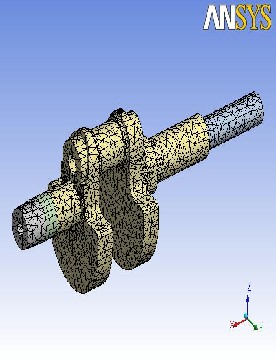
Fig. 2 Crank Shaft (cast iron)meshed
IJSER © 2011
International Journal of Scientific & Engineering Research Volume 2, Issue 8, August-2011 4
ISSN 2229-5518
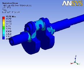
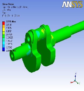
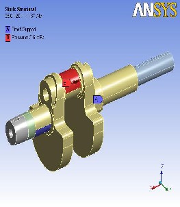 Fig. 6 Crank Shaft (cast iron) Elastic stress
Fig. 3 Crank Shaft (cast iron)loading
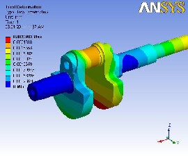
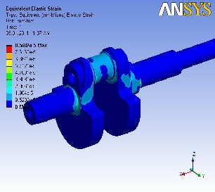
Fig. 4 Crank Shaft (cast iron)Total Deformation
Fig. 7 Crank Shaft (cast iron) Elastic strain
Fig. 5 Crank Shaft (cast iron) Elastic strain
IJSER © 2011
International Journal of Scientific & Engineering Research Volume 2, Issue 8, August-2011 5
ISSN 2229-5518
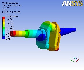
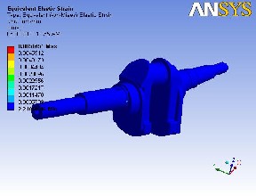
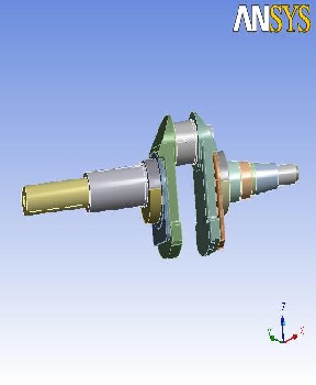 Fig. 10 Crank shaft (Forged steel) Total deformation
Fig. 8 Crank shaft (Forged steel)
TABLE 2
FORGED STEEL PROPERTIES
Structural | |
Young's Modulus | 2.21e+005 M Pa |
Poisson's Ratio | 0.3 |
Density | 7.833e-006 kg/mm³ |
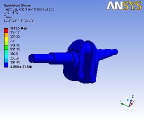
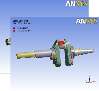 Fig. 11 Crank shaft (Forged steel) Elastic strain
Fig. 12 Crank shaft (Forged steel) Elastic stress
IJSER © 2011
International Journal of Scientific & Engineering Research Volume 2, Issue 8, August-2011 6
ISSN 2229-5518
2) Muhammed Nasiruddin Bin Anidin –“ Finite element analysis of upper crank shaft six stroke engine using CAE Software” – University Malaysia Pahang.
3) Steve Smith – “ Utilizing crankcase deflection analysis to improve crankshaft design and engine performance” – Oxford, U.K
4) Jonathan Williams, Farzin Montazersadgh and Ali Fatemi
–“Fatigue performance comparison and life prediction of forged steel and ductile cast-iron crankshafts” – University of Toledo, Ohio.
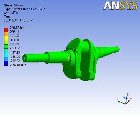
Fig. 13 Crank shaft (Forged steel) Shear stress
TABLE 3
COMPARISON OF PROPERTIES OF FORGED STEEL AND CAST IRON
5) M.Zorouf and A.Fatemi- “The durability evaluation of crankshafts including comparisons of competing manu- facturing processes and cost analysis.
6) Zissions P.Mourelatos –“A crank shaft system model for structural dynamic analysis of internal combustion en- gines”.
7) J.Grum –“Analysis of residual stresses in main crank shaft bearings after induction surface hardening and finish grinding – University of Ljublijana, Slovenia.
8) Xue-Qin Hou, Ying Li,Tao Jiang-“ Fracture failure analy- sis of ductile cast iron crankshaft in a vehicle engine – Bei- jing Institute of Aeronautical Materials ,China.
9) Tian Guanglai,Wei Hanbing,-“Analysis of Stresses in
Forged steel Crankshaft of internal combustion engines
5.CONCLUSION
Analysis results from testing the crank shaft un- der static load containing the stresses and deflection are listed in the Table. Since the forged iron crankshaft is able to withstand the static load, it is concluded that there is no objection from strength point of view also, in the process of replacing the cast iron crankshaft by forged crankshaft. We also reduce forged crankshaft the cost by the mass production. The project carried out by us will make an impressing mark in the field of automo- bile industries. This project we are study about the leaf spring in the automobile vehicles. Doing this project we are study about the 3Dmodelling software (SOLID EDGE) and the Analyzing software (ANSYS) to develop our basic knowledge to know about the industrial design
1) Farzin H. Montazersadgh and Ali Fatemi – “Stress Anal- ysis and Optimization of Crankshafts Subject to Dynam- ic Loading” - FIERF, AISI
IJSER © 2011