International Journal of Scientific & Engineering Research, Volume 5, Issue 4, April-2014 275
ISSN 2229-5518
Comprehensive Overview of Basic Photovoltaic
(PV) Power System
Adil Salman, Muhammad Ibrahim Khalil, Wasim Mukhtar, Muhammad Farooq, Sohaib Ahmad Siddique and Muhammad Saad
Abstract— This paper gives a comprehensive review of Basic Photovoltaic (PV) Power System which can be now considered as one of the most useable renewable electrical power generation technology. This paper is intended to present a broad overview of different possible classifications of PV Power System and their main components including PV Panels, DC-DC Converters, Control System, Maximum Power Point Tracking and enhancement of basic PV Power System.
Index Terms— PV Power System, PV Cell, DC-DC Power Electronic Converter, Control of PV Power System, Maximum Power Point
Tracking (MPPT) and enhancement of Basic PV Power System.
1.) INTRODUCTION
R enewable Energy development has been an increasingly demanding topic in the 21st century due to global warming and several kinds of environmental factors. The
growth rate of renewable is very fast as shown in Fig 1.
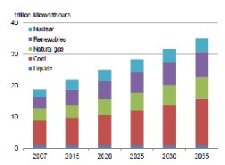
Fig 1. World Electric Power Generation by several kind of fuel
[22]
For Electric Power Generation, various alternative renewable energy sources are gaining popularity. These alternative renewable energy sources include geothermal, wind, water and solar energy.
Although, Solar or Photovoltaic (PV) cells are certainly nothing new, their use has become more common, practical and effective for people worldwide. The main reason why Photovoltaic cells are gaining popularity in the field of electric power generation is due to the fact that they do not emit greenhouse gases, they do not have any rotating part, their life time is very long and during usage they require less maintenance.
Photovoltaic (PV) Cells produce electrical energy when solar
Irradiations fall on their surface. PV cell alone cannot produce
large amount of power so multiple PV Cells need to be used in in the form of module or array which can further be used to implement Photovoltaic Power System.
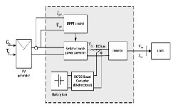
2.) PV POWER SYSTEM
A photovoltaic Power System consists of several components including PV modules or arrays, Converter (DC-DC), Control
System (MPPT) and a load as shown in Fig 2.
Fig 2. A simplified model of PV Power System
According to Fig 2, the converter is used to transfer maximum power to the load from PV Panel by controlling duty cycle of gating (PWM) signal coming from MPPT Control System (Controller).
Every time when sun change its direction, the values of PV Panel parameters start to change which eventually reduce the performance of PV module that is the main reason why a PV Power System consist of several components.
With the help of these components a PV arrays of PV Power System works efficiently at their optimum operating point (MPP) to extract maximum power out of the PV arrays.
IJSER © 2014 http://www.ijser.org
International Journal of Scientific & Engineering Research, Volume 5, Issue 4, April-2014 276
ISSN 2229-5518
3.) CLASSIFICATION OF PV POWER SYSTEM
Photovoltaic (PV) Power System is composed of various inter- connected components which are designed to achieve specific requirements of power. These power requirements can range from powering small devices to feed power into main electric utility system. The classification of Photovoltaic Power System is shown in fig 3.
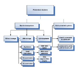
Fig 3. Photovoltaic Power Systems Classification
The two main classification of Photovoltaic Power System are Standalone and grid connected systems [1].The main factor which create a difference between these two configurations is that in Standalone PV Power System the PV Panel output energy is matched with the attached load while in Gird connected PV Power System, the load is not connected directly. Depending on load variations, Photovoltaic Power Systems are usually attached with storage elements like batteries.
If photovoltaic Power System is used together with any other power source like wind turbine etc. then photovoltaic power system falls under the category of Hybrid Power System.
3.1.1 Standalone PV power System
Standalone PV Power Systems are usually used in remote areas where location is not feasible to connect to the main electric utility grid. These kinds of systems are very useful in Telecommunication sector to power up the BTS and in rural areas to power up water pumping systems.
Fig 4. Standalone Photovoltaic Power System
The configuration of standalone systems are somewhat
simpler as compared to other types (grid connected or hybrid).
Mostly, a standalone PV power system contains solar
modules, power conditioners (converters & inverters), control
system, storage system and a load.
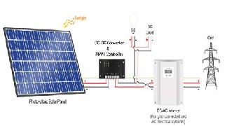
3.1.2 Grid Connected PV Power System
It is a kind of an intelligent PV power system which supplies power to the site loads when needed and when there is an excess power available then it delivers power to the grid[1][2].Grid connected PV Power System is an updated form of a stand alone PV power system with an addition of inverter circuitry which further connected to the grid. As sho
wn in Fig
5
Fig 5. Grid Connected Photovoltaic Power System
Now a days, these kind of power systems are gaining good reputation, Only Germany is producing more than 1GW power from Grid connected systems[2].Furthermore, gird connected PV power system can be divided into centralizaed and decentralized grid connected PV power systems.
4.) DETAILED OVERVIEW OF MAIN COMPONENTS OF PV POWER SYSTEM:
4.1 Photovoltaic Cell
Photovoltaic cell is basically a semi-conductor diode which works on the principle of photovoltaic effect. With the help of Photovoltaic effect PV cell absorb photons from ordinary sunlight and converts them into electrical energy [3]. A typical Photovoltaic Cell is shown in Fig 6.
IJSER © 2014 http://www.ijser.org
International Journal of Scientific & Engineering Research, Volume 5, Issue 4, April-2014 277
ISSN 2229-5518
4.1.2 Characteristics of a Photovoltaic cell
Every Photovoltaic cell has three most important Parameters: Open circuit voltage, Short circuit current and maximum power point. These three parameters are usually given in data sheet of Photovoltaic module (Cell).
Fig 6. PV Cell
Substrate
4.1.1 Operation of a Photovoltaic Cell
In order to understand the operation of a Photovoltaic Cell, consider Photovoltaic Cell as a large semiconductor diode with P-N Homo-junction [4]. The Structure of a Photovoltaic Cell is shown in Fig 7.
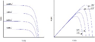
Out of these three parameters and with the help of equation
1,2 and 3 the two main electrical characteristics of a
Photovoltaic Cell can be plotted which are called I-V (Current-
Voltage) and P-V (Power-Voltage) Characteristics as shown in
Fig 9.

𝑞𝑣
𝐼 = 𝐼𝐼ℎ − 𝐼𝐼 (𝑒𝐾𝑇 − 1) (1)


𝑉𝐼𝑉 = �𝐾𝑇� ln(1 + 𝐼𝑝ℎ ) (2)
𝑞 𝐼𝑜
Where:
Pmax= Vmax.Imax (3)
Fig 7. Structure of a PV Cell
P-N Homo-junction is made up of two different materials across which electric field built up. Photons having energy greater than band-gap energy of semi-conductor material move electrons from valance band to the conduction band. This generates electron-hole pair, which flows in opposite direction across the junction in order to generate DC Power [5].
An ideal Photovoltaic cell can be represented by an equivalent circuit with an ideal current source connected with a semiconductor diode in anti-parallel arrangement [6] with equivalent resistances as shown in Fig 8.
Fig 8. Simplified Equivalent Circuit of a Photovoltaic cell
I= Current at terminals of Photovoltaic Cell [A]
Iph= Current due to Photons [A]
IO = Reverse Saturation Current [A]
V= Cell Voltage [V]
T= Cell Temperature [K]
q= 1.6e-19 [OC]
k= Boltzmann’s Constant 1.38e-23 [J/K]
voc= Open Circuit Voltage of PV Cell
Isc= Short Circuit Current of PV Cell
Pmax= Maximum Power of PV Cell
Imax= Maximum Current of PV Cell
Vmax= Maximum Voltage of PV Cell
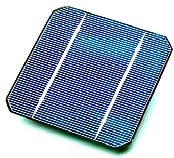
Fig 9. (A) Current-Voltage characteristic of PV module for different irradiances (B) Power- Voltage
characteristics of photovoltaic module for
different temperatures.
IJSER © 2014 http://www.ijser.org
International Journal of Scientific & Engineering Research, Volume 5, Issue 4, April-2014 278
ISSN 2229-5518
Apart from the plot of I-V and P-V Characteristics, these characteristics also varies with irradiance and temperature levels because irradiance variation directly effects current through PV Panel and temperature variation directly effects voltage of a PV Panel which ultimately put observable variation on I-V and P-V characteristics as shown in Fig 9.
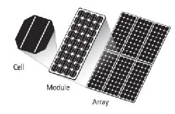
4.1.3 Arrangement of Photovoltaic Panel
In order to drive a small electric device, a single Photovoltaic Cell cannot produce appropriate level of power. Therefore, to get a high level of power, Photovoltaic cells can be connected in series and parallel arrangement to form a module or panel structure. Furthermore, to get rated values of current and voltage, Photovoltaic modules are connected in series and parallel arrangement to form a photovoltaic array as shown in Fig 10.
Fig 10. Photovoltaic Cell, Module & Array Arrangement
4.1.4 Types of Photovoltaic Materials
Semiconductor materials are the core materials that are used
in photovoltaic cells. On the basis of semiconductor materials
[3], photovoltaic cells can be divided into four main groups:
Crystalline Photovoltaic Cell
Thin-Film Photovoltaic Cell
Dye-Sensitized Photovoltaic Cell
Multilayer Photovoltaic Cell
The most dominating types are crystalline photovoltaic cells and thin-film cells. The latter two types can be considered as an extension of thin-film photovoltaic cell category. Further discussion of dominating types of photovoltaic cells is as follows:
Crstallayine Photovoltaic Cell
Single or (Mono) Crystalline Silicon PV Cells:
In past days, mono-crystalline silicon photovoltaic cells were most dominating. But now market has been captured by poly- crystalline silicon photovoltaic cells or even thin film cells. These PV cells are mostly manufactured by the process of Czochralski.
Initially, Mono-crystalline PV cells were popular because of their good level of stability and at the same time having optimum ability to achieve desired electrical, chemical and physical properties [7].The mono-crystal silicon PV cells are more efficient as compared to non-crystalline materials [8].
Poly-Crystalline Silicon PV Cells:
The main reason why poly-crystalline silicon PV cells are dominating is because they are very cheap as compared to mono-crystalline PV cells. The thing that made them cheaper is their manufacturing processes which produce a block with large crystal grain structure. Although these cells are cheaper but at the same time their efficiency [9] is very low.
Miscellaneous Types of Crystalline PV Cells:
Some miscellaneous types of crystalline PV cells are Gallium Arsenide and Ribbon Silicon. Both of these types provide high efficiency and high level of light absorptivity. High cost is the only disadvantage of both of these types.
Thin-Film Photovoltaic Cell
In this type of photovoltaic cells, very thin film of semiconductor material deposited on a low cost substrate such as: Plastic, Metal and Glass etc. with the help of this technology, less material is used and the manufacturing method is also very cheap as compared to crystalline technology. This technology also has high light absorptivity [8].The only disadvantage of thin film technology is its poor cell conversion efficiency. This is due to the fact that thin film PV cells do not have single crystal structure.
Miscellaneous Types of Thin Film PV Cells
Some miscellaneous types of thin film PV cells are Amorphous Silicon, Copper Indium Diselenide and Cadmium Telluride [8]. All of these types are either alloys or either manufactured by a mixture of several compounds. Which not only provide high light absorptivity but they also have less manufacturing cost and energy
IJSER © 2014 http://www.ijser.org
International Journal of Scientific & Engineering Research, Volume 5, Issue 4, April-2014 279
ISSN 2229-5518
consumption. Environmental concerns (e.g. Toxic gases) are their main disadvantage.
4.2 DC-DC Power Electronic Converter
If a PV Panel is directly connected to the load then operating point of PV Panel could not match the operating point of the load attached to it. To overcome this problem, DC-DC converters are used. Mainly, DC-DC Power Electronic Converter regulates output voltage at constant value by taking input from a variable power source such as: Photovoltaic Panel etc. [10].
4.2.1 Classifications of DC-DC Power Electronic
Converters:
On the basis of output voltage levels, DC-DC Converters can be classified into three different types are given below:
Buck Converter
One of the most popular and most basic type of DC-DC Converters is Buck Converter. As the name implies this converter bucked or chopped the amplitude (voltage) of input signal and produce a lower amplitude (voltage) signal at the output with high current level. Sometimes a terminology of step down voltage regulator can also be used for buck converter [10]. Simplified schematic diagram of a Buck converter is shown in Fig 11.
Fig 11. Circuit Diagram of Buck Converter
This converter consist a chopper arrangement at the input stage which is made up of transistor and diode (Q & D). At output stage there is an LC filter to reduce ripples in the output.
The reduction in amplitude of output voltage depends on the duration for which the switching element Q (transistor) remain closed which is further control by a switching control circuit[11].
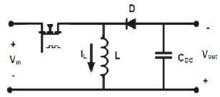
Boost Converter
Boost Converter is also among one of the fundamental types of DC-DC Converters. This converter works in reverse manner as buck converter does. It step up the input voltage by storing Fig 12. Circuit Diagram of Boost Converter
energy in its inductor for a specific amount of time and then utilize this energy to boost the input voltage to a higher level while reducing current to lower level. [11].It also has a capacitor filter at output stage in order to smoothen the output.
Buck-Boost Converter
Buck-Boost converter is a kind of hybrid DC-DC converters which have properties of both buck and boost converters. If the input source voltage is greater than output voltage then converter operates in buck mode and if the input source voltage is greater than output voltage then converter operates in boost mode [12].
Fig 13. Circuit Diagram of Buck-Boost Converter
This converter can be considered as more versatile and intelligent as compared to other types but at the same time its controlling is more challenging.
4.2.2 Operating Modes of DC-DC Converter
During transition from ON State to OFF State, a DC-DC Converter can operate in two modes of operation:
1.) Continuous Conduction Mode
2.) Discontinuous Conduction Mode.
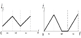
In continuous conduction mode (CCM), current flows from inductor continuously and it never drops to zero during full load operation (As shown in Fig 14).
Fig 14. Inductor current Waveform (a) Continuous Mode (b) Discontinuous Mode
IJSER © 2014 http://www.ijser.org
International Journal of Scientific & Engineering Research, Volume 5, Issue 4, April-2014 280
ISSN 2229-5518
Due to this mode of operation, maximum power can be transferred to the output from a given input signal. In discontinuous mode (DCM), the current through inductor falls to zero and it remains there for a small portion of time until next switching cycle comes (As shown in Fig 14). This mode is
usually used in those
applications where maximum load current is very low, this gives small inductor size and large capacitor size to reduce voltage ripples and maintain output at constant level [13].
4.3 Control of PV Power System
All kind of power electronic converters that have controllable switches (MOSFET) usually require some sort of control system. This control system transfers available power to the output of the converter according to the preset limitations by
providing a controllable duty cycle to the switch. As shown in
Fig 15.
Fig 15. Pulse width modulated signal with various duty cycles
The most popular gate drive signaling technique that is used to control the active switch of converter (MOSFET) is Pulse Width Modulation (PWM) [14]. This is also called duty cycle modulation. In this technique sequential rectangular pulses are used who’s variation in width provide variable duty cycle.
Depending on how much power you need to deliver just vary
Duty cycle of PWM signal as shown in Fig 16.
Fig 16. Closed loop Control of PV Power System [23]
4.4 Maximum Power Point Tracking
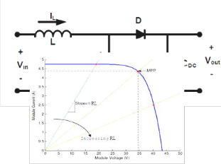
For a Photovoltaic converter the maximum power can be extracted by using V-I characteristics of Photovoltaic cell. The maximum power point (MPP) of these V-I characteristics is variable and mostly mismatched with the maximum power point (MPP) of the attached load. This is due to the fact that V- I characteristics of PV cell are non-linear while the V-I characteristics of load (Resistive) are linear [14]. As shown in Fig 17.
Fig 17. 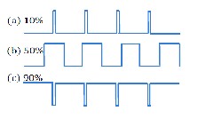 V-I Characteristics of PV Panel with Maximum Power Point
Variations due to loads
In order to match the MPP of PV Panel with the MPP of load, there should be a tracking technique with the help of which MPP can be maintained (tracked). This technique is called maximum power point tracking (MPPT) technique.
With the help of MPPT, the number and size of PV Panels can be
reduced and
DC-DC
converter continuously controlled to operate photovoltaic
IJSER © 2014 http://www.ijser.org
International Journal of Scientific & Engineering Research, Volume 5, Issue 4, April-2014 281
ISSN 2229-5518
panel at its maximum power point despite of possible changes either in load impedance or in external environment of PV Panel.
For MPPT implementation, usually two basic control loops can be considered. One is voltage control loop and the other is current control loop. Mostly, temperature measurement is also included in voltage control loop. The use of these loops depends on the algorithm of MPPT Technique that one can implement on controller. Presently, there are several MPPT algorithms that are using in Photovoltaic Power System industry.
Types of MPPT Techniques
Some of the most frequently used MPPT algorithms are listed below [15] [16]:
Constant Voltage Method Incremental Conductance Method Perturb & Observe Method
Open Voltage Method
Short Circuit Current
Three Point Weight Comparison
Temperature Method
The description of conventional MPPT methods is as follows:
4.4.1 Constant Voltage Method (CV)
Constant Voltage Method is one of simplest methods of MPPT Control. In this method operating point of photovoltaic panel is kept close to the maximum power point by regulating PV panel open circuit voltage and then match it with a fixed reference voltage (Vref) while Vref=Vmpp. (Vmpp is the voltage available at maximum power point on V-I characteristics of PV Panel). Basic algorithm of constant voltage method is shown in Fig 18.
Fig 18. Flow Diagram of Constant Voltage Algorithm [24] Constant Voltage algorithm although very simple but it
always requires an initial measurement of open circuit voltage
of PV Panel in order to decide initial starting point of MPPT.
Most often Maximum Power Point (MPP) voltage is assumed
to be approximately 75% of open circuit voltage of PV Panel
[16].
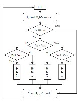
4.4.2 Incremental Conductance Method
The incremental conductance method is one the intelligent methods of MPPT. As the name implies, this method use incremental
conductance,  which (Conductance) is current divided by voltage (reverse of resistance). So, an iterative algorithm based on derivative of conductance (G) is used in it and this technique always tries to
find a point where the derivative of power over current is zero
[17].
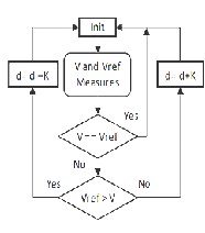
Fig 19.Flow Diagram of
Incremental
Conductance Method
[15]
Incremental
Conductance method
has some issues
when (dG) is not defined. So, this issue can be removed by mixing constant
voltage method with this method [16]. The method that came into existence by this mixture is called Two-Method MPPT Control. Flows diagrams of Two-Method MPPT
IJSER © 2014 http://www.ijser.org
International Journal of Scientific & Engineering Research, Volume 5, Issue 4, April-2014 282
ISSN 2229-5518
algorithm and Incremental Conductance algorithm are shown in Fig 19.
4.4.3 Perturb & Observe Method (P&O)
There is one of the most commonly used methods of MPPT. It is common because it uses a simple technique of perturbing (Power) voltage and current of photovoltaic panel constantly and then measures this new value of power with the previous one and then compute the power variation [17]. If power variation is positive then it shows that MPPT has moved the operating point of PV Panel closer to the MPP and the voltage start to perturb in same direction. If the change in power is vice versa then direction of perturbation is reversed.
There are two basic methods of Perturb and Observe:
1. Perturb and Observe with a fixed perturbing value.
2. Perturb and Observe with a variable perturbing
value.
Fig 20. Flow Diagram of Perturb and Observe Method [23]
Both of the above methods are same except a constant Coefficient (Ka) in first method which is replaced by a variable constant in the second one (Kb). Basic algorithm of Perturb and Observe method is shown in Fig 20.
4.4.4 Comparison of Conventional MPPT Types
Comparison of above mentioned algorithms has been given in Table 2.1 [18]. Where accuracy of algorithm and experimental results are presented.
Table. 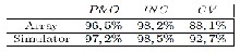 2.1
2.1
Efficiency
of three conventional MPPT Algorithm
From above table, it can easily be observed that Constant Voltage (CV) algorithm has worst efficiency. After CV comes the Perturb & Observe Method and just slightly above P&O
comes Incremental Conductance Algorithm. Although INC has maximum efficiency but at the same time this algorithm is very complex.
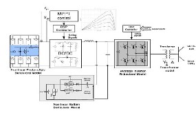
4.5 Extension of PV Power System:
In order to extend PV power system for the application of gird integration or as a emergency backup power system. A combination of battery bank and DC-AC inverter can be implemented (as shown in Fig 21). A battery bank collects and stores energy produced by the PV array for periods. These batteries are long lasting. Common materials which are very popular in the manufacturing of batteries are Cadmium, Lithium Ion and Nickel. 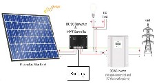
Fig 21. An arrangement of extended PV Power System
4.6 Conclusion
A comprehensive review on PV Power System has been reported in this paper. Due to global warming renewable energy has been an increasingly demanding topic of 21st century, this gives rise to the more and more use of PV Power Systems because they don’t emit greenhouse gases to generate electricity. Different aspects of PV Power System have been briefly addressed in this paper. An effort is made to categorize basic components of PV Power system which includes PV Power Systems and their classification, PV Cell, DC-DC Power Electronic Converter, Control of PV Power System, Maximum Power Point Tracking (MPPT) and enhancement of PV Power System. It is desirable that this review on Basic PV Power System will serve as a useful reference guide to the researchers working in the area of Photovoltaic (PV) Power System.
References
[1] ROGER A. MESSENGER, J. V. (2010). Photovoltaic Systems
Engineering, CRC Press.
[2] H. FELTEN, A. K., AND P. WELTER (2006). Increase in
grid-connected PV system power in Germany. Conference
Record of the 2006 IEEE 4th World Conference. 2496: IEEE
2006, Vol. 2.
[3] LINDGREN, B. (2002). Power-generation, Power-
electronics and Power-systems issues of Power Converters for
Photovoltaic Applications. Department of Electric Power
Engineering. SE-412 96 Göteborg Sweden, Chalmers
University of Technology. DOCTOR OF PHILOSOPHY: 58.
[4] KRAUTER, S. C. W. (2006). Solar Electronic Power
Generation-Photovoltaic Energy Systems. Springer.
IJSER © 2014 http://www.ijser.org
International Journal of Scientific & Engineering Research, Volume 5, Issue 4, April-2014 283
ISSN 2229-5518
[5] HILL, M. D. A. A. R. (2001). Clean Electricity from
Photovoltaic, UK, Imperial College Press.
[6] MAHMUD, N. (2011). Energy Capture Improvement of a
Solar PV System Using Multilevel Inverter. MSc, The
University of Akron.
[7] GWINYAI DZIMANO, B. S. (2008). Modeling of
Photovoltaic Systems. MSc, The Ohio State University.
[8] MAH, O. (1998). Fundamentals of Photovoltaic Materials.
National Solar Power Research Institute.
[9] (2008). Planning and Installing Photovoltaic Systems, USA,
The German Energy Society (Deutsche Gesellshaft fur
Sonnenenergie (DGS LV Berlin BRB).
[10] RASHID, M. H. (2001). Power Electronics Handbook,
Butterworth-Heinemann.
[11] ELECTRONICS, J. (2001). DC-DC Converters: A Primer
[Online].Available:
www.jaycar.co.uk/images_uploaded/dcdcconv.pdf.
[12] YUAN-CHIH CHANG, C.-L. K., KUN-HAN SUN, AND
TSUNG-CHIA LI (2013). Development and Operational Control of Two-String Maximum Power Point Trackers in DC Distribution Systems. IEEE TRANSACTIONS ON POWER ELECTRONICS,, Vol. 28, 10.
[13] RAHMAN, M. S. (2007). Buck Converter Design Issues. MSc, Linköping Institute of Technology.
[14] Safari, N. (2012). Design of a DC/DC buck converter for ultra-low power applications in 65nm CMOS Process. Dept. of Electrical Engineering. Linköping, Linköping University. MSc. [15] Texas Instruments. (2010). Introduction to Photovoltaic Systems Maximum Power Point Tracking. Dallas, USA: Texas Instruments Incorporated.
[16] ROBERTO FARANDA, S. L. (2008). "Energy comparison of MPPT techniques for PV Systems." WSEAS TRANSACTIONS on POWER SYSTEMS Vol. 3(Issue 6).
[17] Simonsen, S. O. (2009). Development of a Grid Connected PV System for Laboratory Use. Department of Electric Power Engineering. Norway, Norwegian University of Science and Technology. Master of Science in Energy and Environment:
146
[18] Ropp, D. P. H. a. M. E. (2000). "Comparative study of
maximum power point tracking algorithms using an
experimental, programmable, maximum power point tracking
test bed." IEEE Photovoltaic Specialists Conference, 28.ss
[19] RasoulRahmani, M. S., SaadMekhilef and RubiyahYusof (2013). "Implementation of Fuzzy Logic Maximum Power Point Tracking Controller For Photovoltaic System." American Journal of Applied Sciences Vol. 3: 10.
[20] PhanQuocDzung, L. D., Hong HeeLe,Le Minh Phuong,NguyenTruong Dan Vu (2010). "The New MPPT Algorithm using ANN-Based PV." IFOST 10.
[21] Roberto F. Coelho, F. M. C., Denizar C. Martins (2010). A MPPT Approach Based on Temperature Measurements Applied in PV Systems. 9th IEEE/IAS International Conference on Industry Applications- INDUSCON 2010 -, IEEE.
[22] (Mahan), S. A. M. (2011). Circuit Topology Study of Grid- Connected Photovoltaic System. USA, The Ohio State University. Graduate Program in Electrical and Computer Science: 79.
[23] A.Pradeep Kumar Yadav, S. T., G.Haritha (2012).
"Comparison of MPPT Algorithms for DC-DC Converters Based PV Systems." International Journal of Advanced Research in Electrical, Electronics and Instrumentation Engineering Vol. 1(Issue. 1): Page No: 6

[24] Dradi, M. H. M. (2012). Design and Techno-Economical Analysis of a Grid Connected with PV/Wind Hybrid System in Palestine (Atouf Village-Case Study). Faculty of Graduate Studies. Palestine, An-Najah National University. MSc: 222

Adil Salman received BSc (Hons) in Electronics Engineering from NFC IET (BZU), Pakistan (2011) and MSc Electrical Engineering (Power) from The University of Nottingham, UK (2013).
His research interests include: Power Electronics, Power Quality and Renewable Energy Systems.

Muhammad Ibrahim Khalil received BSc in Electronics Engineering from NFC IET (BZU), Pakistan (2011) and he is now pursuing MSc in Control Engineering from UET Lahore, Pakistan (2014).
His research Interest include: Control Systems, Automation and Renewable Energy Systems.

Wasim Mukhtar received BSc in Electronics Engineering from NFC IET (BZU), Pakistan (2011) and he is now pursuing MSc in Electrical Engineering (Power) from The University of Bradford, UK (2014).
His research interests include: Power Electronics, Renewable Systems and Control Engineering

Muhammad Farooq received BSc in Electrical Engineering from University of Engineering and Technology (UET), Lahore, Pakistan and presently, he is
pursuing MSc in Electrical Power Engineering from Brandenburg Technical University (BTU), Germany.
His research interests include: Power Systems, High Voltage, and Renewable Energy Systems.

Sohaib Ahmad Siddique received BSc in Electrical Engineering from BZU Multan, Pakistan (2011) and presently, he is pursuing MSc in Electrical Power Engineering from Brandenburg Technical University (BTU), Germany.
His research interests include: Power Systems, Power Electronics, and Renewable Energy Systems.
Muhammad Saad received BSc in Electronics Engineering from BZU Multan, Pakistan (2011) and presently doing MSc in Electrical Engineering from University of Engineering &
IJSER © 2014 http://www.ijser.org
International Journal of Scientific & Engineering Research, Volume 5, Issue 4, April-2014
ISSN 2229-5518
Technology, Lahore, Pakistan, and In Parallel he is working as a lecturer at Pakistan Institute of Engineering and Technology (PIET), Multan, Pakistan.
His research interest include: Control Engineering, Power
Electronics, Power System and Renewable Energy Systems.
284
I£ER 2014 http://WWW.IISer.org