By
1. Lecturer of Civil Engineering, Dayananda Sagar College of Engineering, K.S.Layout, Bangalore – 560078
2. Professor of Civil Engineering, Bangalore Institute of Technology. K.R.Road, Bangalore –560004
![]()
Abstract: This experimental works aims to study (i) the behaviour of Fibre reinforced Concrete Beams(FRCB) without shear reinforcement (ii) the possibility of using steel fibers as shear reinforcement in reinforced concrete beams (RCB). Conventionally the beams are designed with shear reinforcement/ stirrups along with the tensile reinforcement which is expensive because of the labour cost associated with reinforcement installation. Hence, experimental works are carried out to find alternative solution to take care of shear forces without shear reinforcement. The steel fibres of aspect ratio 66.67 were in co-operated in the designed mix with fibre volume fraction (1.0and 1.5%) to study the behaviour of FRCB under two point lading. The test results showed that, the shear reinforcement is not required for FRCB of 1.0% and above upto shear stress of 1.77N/mm2 for concrete of cube strength 36.66 N/mm2 at 28days.
![]()
Plain concrete is weak in tension and has limited ductility and little resistance to cracking. Microcracks are present in concrete and because of its poor tensile strength; the cracks propagate with the application of load, leading to brittle fracture of concrete. Microcracks in concrete are formed during its hardening stage.
A discontinuous heterogeneous system exists even before the application of any external load. When the load is applied, microcracks start developing along the planes which may experience relatively low tensile strains, at about 25-30% of the ultimate strength in compression. Further application of the load leads to uncontrolled growth of the results in a low fracture toughness, and limited resistance to impact and explosive loading.
The low tensile strength of concrete is being compensated for in several ways, and this has been achieved by the use of reinforcing bars and also by applying prestressing methods. Though these methods provide tensile strength to concrete, they do not increase the inherent tensile strength of concrete itself. Further, conventionally reinforced concrete is not a two phase material in true sense. Conventionally reinforced concrete is a true two phase material only after cracking when cracked matrix is held by the reinforcing bars. Existence of one phase (i.e., steel or concrete) does not improve the basic strength characteristics of the other phase and consequently the overall performance of the traditional reinforced concrete composite is dictated by the individual performance of the concrete and steel phase separately.
When a Reinforced Concrete beam subjected to a combination of moment and shear force with either little or no transverse reinforcement can fail prematurely in shear before reaching its full flexural strength. This type of shear failure is sudden in nature and usually catastrophic because it doesn’t give ample warning to inhabitants.
1
According to IS456:2000 to prevent shear failure beams should be reinforced with stirrups. In general, the use of stirrups is expensive because of the labour cost associated with reinforcement installation. Also casting concrete in beams with closely spaced stirrups could be difficult and might lead to voids and associated poor bond between concrete and reinforcing bars.
In recent times development of new materials and production methods have increased within the field of construction. One example is the use of steel Fibres for various applications. Steel Fibres are short and generally deform to enhance bond with concrete. Due to its ability to distribute and prevent cracks from appearing steel Fibres have proved rather effective as crack controlling reinforcement. Hence, an alternative solution to stirrup reinforcement is the use of randomly oriented steel Fibres, which have been shown to increase shear resistance.
conventional steel reinforcement. Steel Fibres greatly increase toughness of concrete, which primarily is used for crack and shrinkage controls, to serves as secondary reinforcement for pavements, slabs, pipes, channel, and tunnels. Its potential improvement to increase toughness, minimise cracking due to temperature changes and resistance due to extreme loading and environment such as impact, abrasion, blasting and fatigue. Furthermore, steel Fibre reinforced concrete greatly reduces the potential for fractures and spalling.
To increase the ductility and to improve the fracture toughness of the concrete the best effect can be achieved by Fibre cocktails or steel Fibres, in several cases by means of polypropylene Fibres as well. Basic requirement to develop the full potency of the used Fibres is a good embedding within the binder matrix. In consequence of the bond between Fibre and surrounding matrix the resistance to Fibre pull-out is given, whereby the Fibre decreases the transferability of tensile stresses within the crack and great crack opening can be avoided, decelerated respectively. Thereby the bridging of the cracks is controlled by the Fibre lengths. Due to the ductile material behaviour implicated by means of the Fibres an abrupt and explosive failure of structural members can be avoided. The best way to increase the mechanical properties is the addition of short plain steel Fibres on condition of even distribution of these Fibres within the matrix. To reach higher ultimate loads, microcracking has to be prevented and consequently the adsorption of tensile stresses has to be increased. That means the function of the Fibres is the prevention of intergrowth of microcracks and therefore the prevention of the devlopment of macrocracking.
Steel Fibres fit excellent into the concrete structure and therefore optimum conditions concerning an even Fibre distribution and 3- dimensional Fibre orientation are given. Thus the structure of the uncracked concrete will be improved. The fine distributed Fibres absorb stresses developing at the crack tip by which the inner crack propagation will be minimised and the structure will be stabilised. Therefore the advantage by using steel Fibres is the improvement of tensile and compressive strength
2
The various materials used for the study were tested in laboratory.The relevant test as per BIS was conducted for the following materials:
Cement
Fine Aggregate
Coarse Aggregate
Fibres
In the present work, Birla Super Ordinary
Portland cement of 53 grade conforming to IS: 12269-1987 has been used. The physical properties of the cement obtained on conducting appropriate tests as per IS:
269/4831 and the requirements as per IS
12269-1987 are given in Table 1![]()
Sl. No | Properties | Values obtained | Requirements as per IS: 12269-1987 |
1 | Fineness | 2.5% | Not more than 10% |
2 | Soundness | 1 mm | Not more than 10mm |
3 | Setting Time: Initial Final | 39 min 380 | Not less than 30 min Not more than 600 min |
4 | Compressive strength: 3 days 7 days 28 days | 38 N/mm2 50 N/mm2 70 N/mm2 | Not less than 27 N/mm2 Not less than 37 N/mm2 Not less than 53 N/mm2 |
5 | Standard consistency | 30% | ------ |
6 | Specific gravity | 3.1 |
![]()
![]()
Locally available clean river sand passing IS:
480 sieves have been used. The fine aggregate was of Zone II with Fineness Modulus of
2.95, Specific gravity = 2.58 and Water absorption = 1.05%. The coarse aggregate
used is crushed (angular) aggregate conforming to IS 383:1970. The maximum
size of aggregate considered is 20mm and downsize, water absorption of coarse
aggregate was 0.70% and had specific gravity of 2.70.
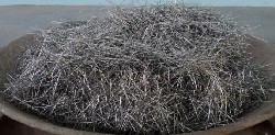
Fibres were straight ones with Modulus of Elasticity of 200 GPa. The Fibres were intended to be randomly placed in the beams at 1.0 and 1.5% by volume. Plate 1 shows the steel Fibres used in experimental work
3
150mm blocks are established by the
compression test conducted on Compressive Testing Machine. The results of compression test conducted on specimens are shown in Table 2.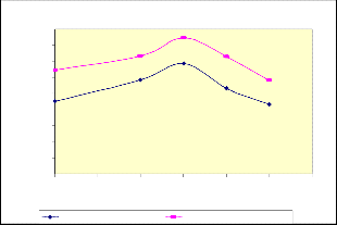
PERCENTAGE OF FIBRES ADDED | STRENGTH IN N/mm2 | |
PERCENTAGE OF FIBRES ADDED | 7 Days | 28 Days |
0 | 22.672 | 32.336 |
1 | 29.212 | 36.607 |
1.5 | 34.371 | 42.292 |
2.0 | 26.596 | 36.362 |
2.5 | 21.727 | 28.879 |
Average Compressive strength
45
40
35
30
25
20
15
10
5
0
From the above result the compressive strength for the plain concrete is
32.336N/mm2, for 1%, 1.5%, 2.0% and
2.5% Fibre reinforced concrete, the strength is 36.607, 42.292, 36.362 and 28.879 N/mm2 respectively. This shows as the compressive strength will increase by the addition of Fibre. Upto 1.5% the compressive strength will increase due to good bonding between concrete and Fibre, after 1.5% the
compressive strength get reduced due to increase in Fibre, clustering of the Fibres and increase in tensile strength.
In the present study, RC and FRC beams were tested. Totally there were 9 beams cast. In that 3 RC beams with stirrups and 6 FRC beams without stirrups (1.0% and 1.5% Fibres added by volume). Curing was done for 28 days
0 0.5 1 1.5 2 2.5 3
Percentage of fibers
7 Days compressive strength 28 Days compressive strength
SPECIMEN Length Breadth Depth Stirrups Nos mm mm mm |
1.5% FRCB 2000 100 300 - 3 |
1.0%FRCB 2000 100 300 - 3 |
RCB 2000 100 300 6mm@220c/c 3 |
The constituent materials used in the cement mixes is given in Table 4
Cement Concrete proportion | 1: 2.65: 3.23 |
Cement | 320Kg/m3 |
Fine aggregate | 849.16Kg/m3 |
Coarse aggregate | 1035.18kg/m3 |
Water-cement ratio | 0.5 |
Steel Fibre used | 1.0% of total volume of concrete |
Steel Fibre used | 1.5% of total volume of concrete |
Steel Fibre used | 2.0% of total volume of concrete |
Steel Fibre used | 2.5% of total volume of concrete |
4
Sand, coarse aggregate and cement were thoroughly dry mixed. Subsequently water was added. The materials were mixed for 3-
5 minutes. Then Fibres were added and mixed again. The fresh concrete was poured into the moulds in three layers. Each layer was compacted using mechanical vibrator. After 24 hours, the specimens were demoulded and cured for 28 days. The specimens were discontinued being cured after 28 days. The beams were mounted on roller supports tested under two point loads. The specimens were tested on a 50T UTM. The loading frame was much stiffer than the beam to be tested.The tests were successfully conducted under load controlled device. 300 mm depth beam was chosen for test on shear carrying capacity of RC and FRC beams.Two 12mm MS rods were provided with a cover of 25mm at the bottom and two 8mm MS rods at the top of the beam. This was to ensure that the flexural failure does not occur. The beams
were mounted on roller supports and tested under two point loads. Load was applied at a distance of 0.4m from the support. A very small increment interval in the loads was ensured using proving ring. Load was applied using the hydraulic load cell. The increment interval was 6 divisions in the proving scale which comes with a calibration chart equating it with the corresponding loads. The approx load interval was around 2kN. Shear reinforcement of 6mm @200mmc/c was provided only for RC beams to ensure failure is in shear only and not in flexure. The deflections at the incremental loads were recorded along with the deflections. The deflections were recorded using the digital dial gauge of 0.001 – 25 mm range. The enhanced shear capacity, if any, has to be evaluated. The crack propagation patterns and the failure pattern are analysed.
Tests were conducted to evaluate the shear carrying capacity of RC with stirrups and FRC
without stirrups and its failure behavior. The behavior of specimens in each test and comparison
of the experimental results
Particulars | Specimen No. | FRCB 1.5% | FRCB 1.0% | RCB |
First crack load (FCL) | 1 | 110kN | 110kN | 96kN |
First crack load (FCL) | 2 | 110kN | 110kN | 82kN |
First crack load (FCL) | 3 | 110kN | 110kN | 88kN |
Ultimate crack load (UCL) | 1 | 150kN | 130kN | 124kN |
Ultimate crack load (UCL) | 2 | 160kN | 130kN | 126kN |
Ultimate crack load (UCL) | 3 | 150kN | 138kN | 124kN |
Failure pattern | 1 | Shear and Flexure | Flexure | Shear |
Failure pattern | 2 | Shear and Flexure | Shear | Flexure |
Failure pattern | 3 | Shear and Flexure | Flexure | Flexure |
Angle of Shear crack | 1 | 0 60 | - | 450 |
Angle of Shear crack | 2 | 0 60 | 0 48 | - |
Angle of Shear crack | 3 | 590 | - | - |
Ratio of UCL/FCL | 1 | 1.363 | 1.182 | 1.292 |
Ratio of UCL/FCL | 2 | 1.454 | 1.182 | 1.536 |
Ratio of UCL/FCL | 3 | 1.363 | 1.254 | 1.409 |
5
Specimen No. | FRCB 1.5% | FRCB 1.0% | RCB |
1 | 4.089N/mm2 | 4.089N/mm2 | 3.568N/mm2 |
2 | 4.089N/mm2 | 4.089N/mm2 | 3.048N/mm2 |
3 | 4.089N/mm2 | 4.089N/mm2 | 3.270N/mm2 |
Avg. Shear stress | 4.089N/mm2 | 4.089N/mm2 | 3.295N/mm2 |
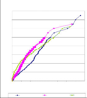
Load Deflections curves
160
140
120
100
80
60
40
performance of FRCB is more ductile than RCB. The failures in RC beams were more sudden and brittle, while those in FRC beams were imminent and very gradual with no abrupt failures. The crack propagated rapidly in the case of RC beams than those in the FRC beams.
The Fibres in the FRC beams appeared to hold the cracks before failure inducing a kind of pinching effect on the surrounding
20
0
0 1 2 3 4 5 6 7 8
Average Deflection at supports in mm
beams to deflect more. The average shear carrying capacity in FRCB 1.5% is 150kN, FRCB 1.0% is 130kN and 124kN in RC
FRCB 1.5% FRCB 1.0% RCB
1.5%, FRCB 1.0% and RCB
The performance of both FRCB 1.5% and FRCB 1.0% specimens initially behaved differently and then almost uniformly up to the first crack load. Peak load carrying
almost vertical with an almost sudden catastrophic failure. The crack in FRCB was more torturous with inclination at around
60o. The failure was less sudden than that in
RCB.
Important conclusion can be drawn from the experimental investigation that no shear reinforcement is required for FRCB of 1.0% and above upto shear stress of 4.0N/mm2, taking load factor at 1.5. The maximum shear etess permitted is 2.66 and the average shear stress that can be permitted is 1.77N/mm2 (for Rectangular cross section) for grade of
concrete of cube strength 36.66N/mm2 at 28 days
Increase in percentage of steel Fibres behyond 1.0% are not yielding better results with
respect to shear.
Since angle of shear cracks is more than 450, the FRCB are more shear resistant than RCB.
Initial behaviour of FRC beams are different but, in all FRCB first crack load is same i.e., at
110kN.
The steel Fibres can be used as minimum shear reinforcement in unreinforced concrete beams.
6
Increase in Fibres increases deflection but prevents the failure due to excessive deflection, as the Fibre posses high tensile strength which binds together the matrix and thus preventing fracture or failure
FRC beams without stirrups exhibutes more load carrying capacity than RC beams with
stirrups.
Compressive strength of Fibre reinforced concrete increases with increase in Fibre up to
1.5% beyond which there is clustering of Fibres in one place which thus reduces the compressive strength.
Fibres not only decrease crack width but also reduce the number of cracks.
Sanat K.Niyogi and G.I.Dwarakanathan-
”Fibre reinforced beams under moment and shear”_ ASCE Journal of Structural Engineering, Vol. 111, No. 3, March 1985, pp 516-527.
M. A. Mansur, M. ASCE, K. C. G. Ong, and P. Paramasivam-“ Shear strength of fibrous concrete beams without stirrups”_ ASCE Journal of Structural Engineering,
Vol. 112, No. 9, September 1986, pp 2066-
2079.
E.I.EI-Niema-“Reinforced concrete beam with Steel Fibres under shear”_ACI Structural Journal, Vol.88, No.2, March- April 1991, pp 178-183.
K.H.Tan, K.Murugappan and P.Paramasivam-“Shear Behavior of Steel Fibre Reinforced Concrete Beams”_ ACI Structural Journal, Vol.89, No.6, Nov-Dec
1992, pp 173-181.
H. V. Dwarakanath and T. S. Nagaraj-“ Deformatioal Behaviour of Reinforced Fibre Reinforced Concrete Beams in Bending”_ ASCE Journal of Structural Engineering, Vol. 118, No. 10, October
1992, pp 2691-2698.
Dr. Rafat Siddique- “Special Structural
Concretes”_Galgotia Publications pvt. Ltd,
2000, pp 01-87.
Yoon – Kwak, Mark.O.Eberhace, Woo- Sukkim and Jubum Ki- “Shear strength of steel Fibres- reinforced concrete beams without stirrups”_ACI Structural Journal, Vol.99, No.4, July-August 2002, pp 530-
538
Aurelio Muttoni and Miguel Fernández Ruiz-“Shear Strength of members without Transverse Reinforcement as function of critical shear crack width”_ ACI Structural Journal, Vol.105, No.2, March -April
2008, pp 163-172.
Tom Greenoudh and Moncef Nehdi-“Shear Behavior of Fibre- Reinforced Self Consolidating Concrete Slender Beams”_ACI Structural Journal, Vol.105, No.5, September- October 2008, pp 468-
477.
P. Colajanni, A.Recupero and N.Spinella- “A model for SFRC beams without shear reinforcement”_ Taylor and Francis Group, London, 2008, pp 619-624.
Salah Altoubat, Ardavan Yazdanbakhsh, and Klaus- Alexander Rieder- “Shear
Behavior of macro Synthetic Fibre
Reinforced Concrete Beams without stirrups”_ ACI Structural Journal, Vol.106,No.4, July-August 2009, pp 381-
389.
S. Pant Avinash and R.Suresh Parekar-
”Steel Fibre reinforced concrete beams under combined torsion , bending, shear”_Journal of Civil Engineering(IEB), Vol.38, No.1, 2010, pp 31-38.
Yen Lei Voo, Wai Keat Poon and Stephen J Foster-“Shear strength of steel Fibres reinforced UHPC beams without stirrups”_ ASCE Journal of Structural Engineering, April 2010, pp 01-28.
7