International Journal of Scientific & Engineering Research, Volume 3, Issue 9, September-2012 1
ISSN 2229-5518
Comparison of some Classical PID and Fuzzy
Logic Controllers
Eisa Bashier M. Tayeb and A. Taifour Ali
Abstract— The proportional-integral-derivative (PID) controller is tuned to find its parameters values. Generally most of the tuning methods depend mainly on the experimental approach of open-loop unit step response. The controller parameters can be found if the system truly can be approximated by First Order Plus-Dead Time (FOPDT). The performance of most of them deteriorates as the ratio of approximated equivalent delay L to the overall time constant T changes. On the other hand fuzzy PID controller is not tuned through the same conventional tuning procedures. It’s constructed as a set of control rules and the control signal is directly deduced fr om the knowledge base and the fuzzy inference. Fuzzy controller parameters tuned by starting from the equivalent values obtained for optimum controller. The performances of different PID tuning techniques are simulated for different order systems and compared wi th fuzzy-PD+I controller. MATLAB simulation results show that Fuzzy PD+I have better performances over other conventional PID controllers.
Index Terms — Fuzzy PD+I Controller, PID Controller Tuning, Controllers Comparison, Tuning Techniques.
—————————— ——————————
he PID controller has several important functions; it pro- vides feedback, has the ability to eliminate steady state offsets through integral action, and it can anticipate the future through derivative action. PID controllers are the larg- est number of controllers found in industries sufficient for
solving many control problems.
The determination of the controller parameters is called the
controller tuning or design. Many approaches have been de-
veloped for tuning PID controller and getting its parameters
for single input single output (SISO) systems. Among the well-
known approaches are the Ziegler-Nichols (Z-N) method, the Cohen-Coon (C-C) method, integral of squared time weighted error rule (ISTE), integral of absolute error criteria (IAE), in- ternal-model-control (IMC) based method, gain-phase margin
method [1-9]. This paper focuses on studying the FPID and
derived, then various design techniques for determining the controller parameters can be applied. However, if the plant is so complex that its mathematical model cannot easily be ob- tained, then analytical approach to design PID controller is not possible [11]. Then we must resort to experimental approaches for tuning of PID controllers.
Optimum setting algorithms for a PID controller were pro- posed by Zhuang and Atherton [19] for various criteria. The methods involve searching for minimum of the cost
function J n ( ) in its general form:
compares it with optimum tuning method, Z-N which has been explored since 1942 and is still used in industry and C-C.
jn (
) [t n e(
0
, t)]2 dt
…… (2)
The PID control law is the sum of three types of control ac- tions: a proportional, an integral and a derivative control ac- tions. Mathematically PID controller in the time-domain is given by the following equation:
t
Where e( , t) is the error signal, with as PID control-
ler parameters. The optimum controller parameters are found when the partial derivative of J n ( ) with respect to
equals zero. The error signal used for optimization can
be a result set-point or of load disturbance. Therefore, it is
u(t) K
![]()
[e(t) 1 e( )d T
![]()
de(t) ]
…(1)
possible to obtain two sets of parameters: one for the set-
Ti 0 dt
Where u (t) is the controller output (input signal to the plant model), the error signal e(t) is defined as e(t) =r (t) − y (t), and r (t) is the reference input signal while y(t) is the output. The controller parameters are proportional gain Kp, integral time Ti, and derivative time Td [10].
If a mathematical model of the PID-controlled plant can be
————————————————
Eisa Bashier M., PH-00249915458516. E-mail: eisabashier@yahoo.com;
Co-Author A. Tayfoor Ali. E-mail: ayha_114@yahoo.com;
Both authors are assistant professors at: School of Electrical and Nuclear
point input and the other for the disturbance signal. In par- ticular, three values of n (n = 0, 1, 2) are discussed. These three cases correspond, respectively, to three different op- timum criteria: the integral squared error (ISE) criterion, integral squared time weighted error (ISTE) criterion, and the integral squared time-squared weighted error (IST2E) criterion. The expressions given were obtained by fitting curves to the optimum theoretical results [19, 20].
A large number of industrial plants can approximately be modeled by the first order plus dead time (FOPDT) model with transfer function as follows [21]:
Engineering; College of Engineering; Sudan University of Science
&Technology
G(s)
K
![]()
Ts 1
e Ls
….… (3)
IJSER © 2012
The research paper published by IJSER journal is about Comparison of some Classical PID and Fuzzy Logic Controllers 2
ISSN 2229-5518
Sometimes one may want to design a controller having good rejection performances on the disturbance signal. The parameters equations to design controllers for disturbance rejection using the optimal method are different than the set point used here.
PID controller equation suggested by Z-N is:
e(n) E(n) GE
ce(n) CE(n) GCE
Rule
Base
u (n)
1
u(n) U(n)
T 1 w GU
![]()
![]()
GZN (s) 1.2 (1 0.5Ls)
L 2Ls
suggested gains setting as:
… (4)
And C-C
ie(n) IE(n) GIE
u (n)
2
K p
![]()
1.25 (1
a
0.18
![]()
1
Ti
![]()
2.5 2 L
1 0.39
… (5)
U (n) f (GE * e(n), GCE * ce(n)) * GU f (GIE * ie(n)) * GU
(7)
![]()
T 0.37 0.37 L
d 1 0.81
Where, the functions f1, f2 are the input-output map of the fuzzy controller and G stands for gain.
Where;
a k
![]()
p L T
& . ![]()
L (L T )
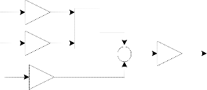
One way of constructing such controller is achieved by sum- ming the fuzzy PD controller output and the integral part. In
While the gains of optimal PID controller can be set as follows
many simple systems, Fuzzy logic integral control is able to
[19]:
K a1 L
work however it's slow. This slower response can be reduced
by combining I-controller with another form, such as P or PD![]()
![]()
p
controller. Thus the proposed fuzzy logic controller is FPD+I
Ti
k T
T
![]()
….… (6)
controller [22, 23].
In this paper the inputs to fuzzification block are chosen to be
a2 b2 (L / T )
b3
![]()
T a T L
d 3
T
Where the parameters (a, b) should be determined according to Table A1 in appendix A. the selection of (a, b) depends mainly on the value of (L/T).
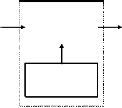
The three principal elements to a fuzzy logic controller are shown in figure (1).
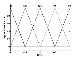
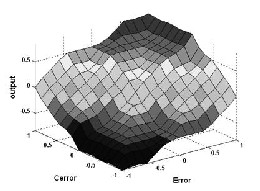
the Error (E) and its derivative (d(E)/dt). The type of the FLC used is Mamdani-type which has fuzzy rules of the form IF- THEN rules. All membership functions for controller inputs (E and change of E) and controller output are defined on the common normalized domain [-1, 1]. Fig.(3) shows the In- puts/Output relations of the FPD Controller.
Table 1: Rules for Fuzzy PD-Controller
N o n - fu zz y
![]()
In p u t
F u z z y R u le b a se
N o n -fu z z y
![]()
O u t put
(a) Membership functions
IJSER © 2012
The research paper published by IJSER journal is about Comparison of some Classical PID and Fuzzy Logic Controllers 3
ISSN 2229-5518
From the step response we obtained the parameters (K, L, and T) as (K = 8.333, L = 0.3725, T = 1.0442). The range of (L/T) from the given transfer function is equal to (0.3725/1.0442)=0.3557. The parameters of the controller are obtained as in Table (3):
Table 3: The Controller Parameters of System2
PID Controller Parameters | |||
Criterion | Kp | Ti | Td |
Z-N | 0.4036 | 0.7450 | 0.1863 |
C-C | 0.4475 | 0.8600 | 0.1291 |
IST2E | 0.2949 | 1.1775 | 0.1316 |
(b) Out-
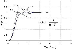
System3; G3
(s)
4
![]()
(s 1) 4
………(10)
put surf of the controller.
The inputs and outputs are transformed to five fuzzy linguis- tic variables NB, NS, Z, PS, and PB which stand for Negative Big, Negative Small, Zero, Positive Small and Positive Big re- spectively.
From the step response we obtained the parameters (K, L, and T) as (K=2, L=2, T=2). The range of (L/T) from the given trans- fer function is equal to 1. Table (4) shows the parameters of the different controllers.
Table 4: The Controller Parameters of System3
The key feature in the optimum methods for PID controller tuning is to obtain the response of the plant to a unit step input. If it involves neither integrator nor dominant complex- conjugate poles, then such an open-loop unit step response curve may be characterized by three constants, gain K delay time L and time constant T [10].
System4; G4
(s)
3
![]()
(s 2)( s 1) 6
…(11)
The following is an example of PID-controlled systems and their responses for different ratios when tuned using Z-N and C-C methods.
These constants are either to be found experimentally or in- stead of experimental approaches, a simulation may be used to get these parameters. In the following are different systems ex- amined to illustrate the method for tuning the controllers.
From the step response we obtained the parameters (K, L, and
T) as (K =1.5, L =4, T=2.5), L/T=1.6; Therefore the parameters
of the controller are obtained as in Table (5).
Table 5: The Controller Parameters of System4
System1; G
1
( s )
120
![]()
( s 2 6 s 3)
…. (8)
From the step response we obtained the parameters (K, L, and T) as (K = 40, L = 0.174, T =1.826). The range of (L/T) from the given transfer function is equal to (0.174/1.826)=0.095.
Table 2: The Controller Parameters of System1
PID Controller Parameters | |||
Criterion | Kp | Ti | Td |
Z-N | 0.3143 | 0.3485 | 0.0871 |
C-C | 0.3330 | 0.507 | 0.0633 |
IST2E | 0.2024 | 1.92 | 0.071 |
200
5 SIMULATION RESULTS AND DISCUSSIONS
In this section, a simulation for the four different systems is carried out according to the parameters values obtained in the tables 2 to 5. Fuzzy controller parameters start from values obtained for optimum controller. Then this FPD+I controller is finely tuned by adjusting GE, GCE, GIE and GU. A compari- son is made based on the parameters characterizing transient response. Fig.(4) to Fig.(7) show the closed-loop step response for each method.
For the different tested systems, the FPD+I gives accepted rise time, the best settling time and perform very much better than others in the overshoot behavior. This controller gives very fast response especially for lower order systems. For higher
System2; G2 (s)
![]()
(s 1)( s 4)( s 6)
…(9)
order systems the responses of Z-N results in longer settling
time and approaching critically damped systems which consi-
IJSER © 2012
The research paper published by IJSER journal is about Comparison of some Classical PID and Fuzzy Logic Controllers 4
ISSN 2229-5518
dered as its shortcoming.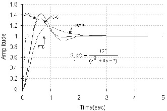
The PID control is still of great interest, and is a promising control strategy that deserves further research and investiga- tion. These tuning methods are only valid for open loop sys- tem which can be described by the first order plus dead-time model and for 'ideal' PID control structure case.
FPD+I controllers show better results than optimally tuned
PID, C-C and Z-N. The response of the later deteriorates as the approximated equivalent delay L to the overall time constant T increases. Optimally tuned controller sustain for wide range of systems due to their consideration to L/T.
[1]. J. G. Ziegler and N. B. Nichols, (1942) ―Optimum settings for automatic controllers,‖ Transactions of American Society of Mechanical Engineers, Vol. 64.
[2]. G. H. Cohen and G. A. Coon, (1953) ―Theoretical investiga-
tion of retarded control,‖ Transactions of American Society of
Mechanical Engineers, Vol. 75.
[3]. M. Zhuang and D. P. Atherton, (1993) ―Automatic tuning
of optimum PID controllers,‖ IEE Proceedings on Control and
Applications, Vol. 140.
[4]. D. W. Pessen, (1994) ―A new look at PID-controller tun-
ing,‖ Journal of Dynamical Systems Measures and Control, Vol.
116.
[5]. M. Morari and E. Zafiriou (1989) "Robust Process Control" Prentice-Hall, Englewood Cliffs, New Jersey.
[6]. W. K. Ho, C. C. Hang, and L. S. Cao, (1995) ―Tuning of PID controllers based on gain and phase margin specifications,‖ Automatica, Vol. 31,.
[7] P. Cominos, N. Munro. (2002) PID Controllers: Recent Tun-
ing Methods and Design to Specification. in: IEE Proceedings,
Control Theory and Applications, vol. 149, 46–53.
[1] C. Lee. (2004) A Survey of PID Controller Design based on
Gain and Phase Margins. International Journal of Computational
Cognition, 2(3): 63–100.
[9] G. Mann, B. Hu, R. Gosine. (2001) Time Domain based De-
sign and Analysis of New PID Tuning Rules. IEE proceedings, Control Theory Applications, 148(3): 251–261.
[10]. Karl J.Astrom and Tore Hagglund, (1995) ―PID Control- lers: Theory, Design, and Tuning,‖ .Instrument Society of Amer- ic.
[11]. Katsuhiko Ogata, (1997) ―Modern Control Engineering 3rd Edition‖. Prentice-Hall, Inc, Simon & Schuster/A Viacom Company.
[12] S. G. Tzafestas, (1994) ―Fuzzy systems and fuzzy expert
control: An overview,‖ Knowl. Eng. Rev., vol. 9, no. 3, pp. 229–
IJSER © 2012
The research paper published by IJSER journal is about Comparison of some Classical PID and Fuzzy Logic Controllers 5
ISSN 2229-5518
268.
[13] S. G. Tzafestas and N. P. Papanikolopoulos, (1990) ―In-
cremental fuzzy expert PID control,‖ IEEE Trans. Ind. Electron.,
vol. 37, no. 5, pp. 365–371.
[14] S.-Z. He, S. Tan, and F.-L. Xu, (1993) ―Fuzzy self-tuning of
PID controllers,‖ Fuzzy Sets Syst., vol. 2, pp. 37–46.
[15] Z.-Y. Zhao, M. Tomizuka, and S. Isaka, (1993) ―Fuzzy gain
scheduling of PID controllers,‖ IEEE Trans. Syst., Man, Cybern.,
vol. 23, no. 5, pp. 1392–1398.
[16] S. Chopra, R. Mitra, V. Kumar. (2005) Fuzzy Controller:
Choosing an Appropriate and Smallest Rule Set. International
Journal of Computational Cognition, 3(4): 73–78.
[17] H. Ying. (2000) Fuzzy Control and Modeling: Analytical Foundations and Applications. IEEE Press series on Biomedi- cal Engineering, New York,.
[18] Stefan Preitl, Radu-Emil Precup, Zsuzsa Preitl (2010) ―As- pect Concerning the Tuning of 2-DOF Fuzzy Controllers‖ Au- tomatic Control and Robotics Vol. 9, No 1, pp. 1 - 18
[19]. Dingyu Xue, Yang Quan Chen, and Derek P. Atherton.,
(2007) ―Linear Feedback Control‖. The Society for Industrial and
Applied Mathematics.
[20] L. Eriksson, (2005) ―A PID Tuning Tool for Networked
Control Systems‖, WSEAS
Transactions on Systems, Vol. 4, Issue 1, pp. 91-97.
[21]. Saeed Tavakoli and Mahdi Tavakoli (2003) "Optimal Tun- ing Of PID Controllers For First Order Plus Time Delay Mod- els Using Dimensional Analysis" International Conference on
Control and Automation (ICCA’03).
[22]. E. B. M. Tayeb, F. A. Hussein ―Automatic Generation
Control of an Interconnected Power System Using Fuzzy Log-
ic Control‖ M.Sc. thesis, College of Engineering, SUST, Khar-
toum (2010).
[23] Satish. R. Vaishnav , Zafar. J. Khan ((2010)) ―Performance
of tuned PID controller and a new hybrid fuzzy PD + I con-
troller‖ World Journal of Modelling and Simulation; Vol.6 No.2,
pp. 141-149
![]()
![]()
Table A1: Set-point PID controller parameters
IJSER © 2012