International Journal of Scientific & Engineering Research, Volume 4, Issue 12, December-2013 1724
ISSN 2229-5518
Comparison of Macrobend Losses In Single
Mode Fibre (SMF) And Multimode Fibre (MMF)
1D.Nhiwatiwa, 1K. Munjeri, 1E. Mashonjowa, 2M. Munyaradzi, 2B. M. Nyambo,
1Physics Department 2 Computer Science Department, University of Zimbabwe, Harare, Zimbabwe
dnhiwatiwa@yahoo.com munjerik@yahoo.com, emashonjowa@gmail.com, mmunyaradzi@science.uz.ac.zw, nyambo@science.uz.ac.zw.
Abstract -- This paper presents a comparison of macrobend losses in Single Mode Fibre (SMF) and Multimode Fibre (MMF). The increased demand on information has seen optical fibres slowly replacing the use of copper coaxial cables for signal transmission, and this is largely due to the high bandwidth and speed of transmission, large carrying capacity and security offered by optical fibres. Signal attenuation however remains a limitation to efficient and quality signal transmission. Macrobending is one of the loss mechanisms that contribute to this signal attenuation. Appreciating the responses of the different optic fibres in use, to macrobending is therefore instrumental in ensuring macrobending contribution to overall attenuation in optic fibres is minimised. In this study the macrobend losses trends with bending diameter were investigated for the SMF and MMF in similar experimental setups. To do this, improvisions were done for a light source using 555 timer astable multivibrator powering a green light emitting diode (LED), a light detector using an LDR in a Wheatstone bridge circuit and optic fibre optic off-cuts. Optic power was measured at the input and output points of the optic fibres using the light detector in bend and straight conditions for determination of signal attenuation in each case. The experimental measurement results showed that macrobending losses are more pronounced in a SMF than in a MMF. Characteristic values for macrobending loss are
1268 dB/km for SMF compared to 1155 dB/km for MMF for bending diameter value 4.19 cm. The SMF macrobending loss trend showed an exponential variation which agrees with work done by other researchers. The contribution of macrobending loss in multimode fibre attenuation was however minimal and therefore difficult to quantify. Results also showed that MMF have a higher overall signal attenuation than SMF which justifies the use of SMF in long distance signal transmission. Research findings confirmed the significant contribution of macrobending to optic fibre signal attenuation hence the need for careful consideration in installations for optimal operation of optic fibres.
Keywords: Attenuation, Light detector, Light source, Macrobending loss, Multimode Fibre (MMF), Single Mode fibre (SMF).
1 INTRODUCTION
The development of Fibre Optic cables in communications has received much attention in recent years. Such transmission waveguides are quite important given the expected future increase in the demand for greater bandwidth in many parts of the world including Africa. Information and data use has become so widespread across all ages in developed and developing countries. This has been made possible by the continued reduction of cost for accessing such services aided by the increased use of optic fibres for signal transmission.
An optic fibre operating at 10 Gbps for example, can handle over 130,000 simultaneous voice channels compared to about 2000 voice channels that can be carried by one of
various loss mechanisms present in the optic fibre system [3]. The overall attenuation in an optic fibre is the sum of signal power losses due to absorption, scattering, micro bending, macrobending and other loss mechanisms. Minimum attenuation or power loss is however paramount for efficient use of fibres in telecommunications and several other application fields.
Continuous research and development has managed to
significantly reduce the overall attenuation of signals in optic fibres. Macrobending is one of the most important loss mechanisms resulting in signal power loss. It is therefore important to characterise macrobend losses for different bend diameters, types of optic fibre and wavelengths of signals so that choice of optic fibre in any application is done to achieve minimal losses due to macrobending. Attenuation in (dB/km)
the best copper coaxial cables [1], [2]. Optic fibres are
= log � � where I
= the measured output power, I
= the


L Ii o i
usually installed underground for long distance
transmission and due to the nature of terrain; at times it is
inevitable that the cables are bend. There are three major
types of optic fibres namely multimode fibres (MMF),
single mode fibre (SMF) and plastic optic fibre (POF). Light
propagating in an optic fibre is attenuated due to the
reference input power and L = the length of the optic fibre.
IJSER © 2014 http://www.ijser.org
International Journal of Scientific & Engineering Research, Volume 4, Issue 12, December-2013 1725
ISSN 2229-5518
2 LITERATURE REVIEW
2.1 Signal Attenuation in Optic Fibres
Attenuation of signals is a significant factor that should be considered in optic fibre communication [4]. This is because it determines the cost of fibre optic telecommunication systems as it determines spacing of repeaters needed to maintain acceptable signal levels that inturn ensures quality and correct delivery of signals. Attenuation in optic fibres is dependent on fibre properties, structure and transmission characteristics such as wavelength [5].
Remarkable progress has been made in reducing the transmission loss from 20 dB/km to about 0.2 dB/km, and in the recent years this has further reduced to 0.002 dB/km [6],
[7].
The attenuation can be classified into two:
i) Intrinsic losses – this refers to losses caused by substances inherently present in the fibre like impurities and imperfections in the glass. An example of an intrinsic loss is material absorption and Rayleigh scattering.
ii) Extrinsic losses- this defines losses or attenuation caused by external forces such as macrobending.
more pronounced than loss due to other loss mechanisms such as absorption [13].
Multimode fibre measurements are a bit difficult to take in that light travels in several modes and the effect of macrobending can be insignificant such that it may be difficult to detect in an experimental situation. These modes have their own bend sensitivity and it is difficult to measure modes loss independently. Researches on macrobending loss in multimode fibres have made use of models [12], 16]. Kauffman et al [12] have shown that the overall power loss that is due to bending has a non monotone structure as a function of the radius of curvature of the bending .
Derivation of a loss coefficient associated with the
curvature loss is done for a whole fibre, but to do so require
knowledge of both the initial power distribution among the modes and the coupling between the modes which is assumed negligible. The bend-loss model has been used to determine macrobend losses as a function of the number of mandrel wraps (turns) and the launch conditions. The bending loss was also found to depend strongly on the launch conditions [9].
Several light sources can be used ( ie from LED, laser and
mercury vapour lamp). In actual operation, because of their
properties, single mode fibres make use of laser as the light
source whilst multimode fibres use LEDs. However for
2.2 Bending Loss
research purposes mercury vapour lamps, LEDs and lasers are used interchangeably in order to investigate wavelength
Bending loss in the form of macrobending and microbending
is a major loss mechanism that contributes to loss as light
propagates along the fibre. Microbends are microscopic bends
of an optic fibre that arise due to poor cable design and
transportation. Gloge and Marcuse [6], [8] have shown that
such bends do not need to be of large amplitude to cause losses of a few dB/km. It is therefore important that care should be taken in order to minimise these perturbations that may have an effect on the fibre’s transmission [9]. Macrobends on the other hand, are bends on a fibre having a large radius of curvature (bend) or large diameter relative to the fibre core radius or diameter that is r>>a where a, denotes the core radius, and r the radius of curvature [3], [10], [11].
A number of scientists have researched and made findings on macrobend losses in both single and multimode optic fibres [3], [6], [9], [12], [13]. Macrobend losses have been
found to depend on the bend diameter or radius of curvature of the optical fibre and the wavelength of the propagating light in the case of SMF. If radius of curvature of the bend of the optical fibre is small and the transmitted light is long, the macrobending loss in the optical fibre has been observed to increase [14].It has been observed that below a critical radius, the bend radius beyond which attenuation rapidly increases, the macrobending loss becomes significant and noticeable [9], [15]. It is therefore crucial to avoid radius of curvatures approaching the critical radius in installations and transportation of these optic fibre cables. Findings by Quino, suggests that loss due to bending in the visible light range is
dependence on fibre losses. In our case, the light source used was an LED. A light detector circuit was used in place of an optical spectrum analyser to measure light intensity for determination of attenuation in optic fibres.
This study thus seeks, firstly to make a comparison of
macrobend losses in Single Mode Fibre (SMF) and Multimode
Fibre (MMF), secondly to investigate the macrobend losses in
both single mode fibre and multimode fibre subjected to
similar experimental conditions so that differences in the macrobending losses could only be attributed to the structure and properties of these fibres.
3 MATERIALS AND METHODS
3.1 Introduction
Materials used in carrying out the research included the light source, light detector and fibre and bending material.
The light source consisted of a 5 mm extra illuminant
LEDs (green) wavelength 520 – 560 nm, NE55532P 555 timer,
250 kΩ variable resistor, Resistor 1, 12 V Power supply, Resistor and an aluminium box painted black inside and outside with a 2.1mm slit. The Light Detector was made up of a 12 V digital power supply, UNIT-T UT39A Digital multimeter, Resistors R1 =100 kΩ, R2 = 100 kΩ, R3 =12 kΩ,
26.6 cm x 16 cm x 19 cm wooden box, Vero board, and an
LDR (Light Dependant Resistor). The Fibre and bending
IJSER © 2014 http://www.ijser.org
International Journal of Scientific & Engineering Research, Volume 4, Issue 12, December-2013 1726
ISSN 2229-5518
material were, 1x2 m Single Mode fibre, 1x2 m Multimode fibre, Masking tape, Metre rule, 3 x clamp and stand, Hollow cylinders of several diameters.
The light source circuit was to serve as the signal source. Two circuits were initially designed for light detection, one using a phototransistor and another using an LDR and connected as shown in fig 3.1a and 3.1b
C1

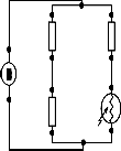
0.1uF
R1
The respective components were soldered onto a Vero board and the circuit enclosed in a wooden box. The wooden box was painted black inside to isolate the light from the optic fibre end and had terminals to which bias voltage and the digital multimeter were connected.

12V
Varying positions of light source (I-V)
10M
+Vcc
+
-Vcc
Vout
+
12V
-
R1
100k
R2
100k
R3
12k
Rx
A I II III IV V
V
0V
a. b.
Fig 3.1: Phototransistor light detector circuit and LDR circuit
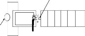
The response graphs of the two available different phototransistors were determined in turn by varying the
Fig 3.3: Circuit for determining I-V characteristics of an LDR
3.2 Measurements
The single mode fibre was carefully aligned to the light source and positioned to maximise the light intensity getting
IJSER
light intensity falling on the phototransistors. See fig 4.1
and 4.2. The response graph of the circuit in fig 3.1b was
determined by varying the light intensity falling on the LDR. The choice of the varying positions of the light source was such as would fit on the retort stand and spaced enough for characterising each of the light sensors appropriately. The response graph of the LDR is shown in
into optic fibre. The output from the optic fibre was focused
onto the LDR and the out of balance voltage of the bridge
circuit recorded. Measurements were done for both the
straight and bend conditions of the fibre. The bend diameters
used were 10.02cm, 7.41cm, 6.50cm, 5.11cm, 4.19cm, 3.33cm,
2.82cm, 2.15cm, and 1.92cm.
fig 4.3.
Aluminium box
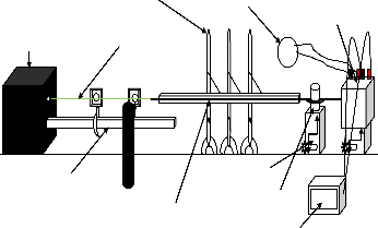
Clamp and stand
Beam of light
Digital multimeter
Detector circuit
mounted in wooden box
V
Varying positions of light source (I-VI)
V
Voltmeter
Light detector circuit
I II III IV V VI
Optic bench
Lens in lens holder
Optic fibre fixed to metre rule
Adjustable stand
Hollow cylinder
12V
Position of LDR/
Phototransistor
Power supply
Fig 3.2: Connection for determining response curve for the two different designs
The current voltage (IV) characteristics of the LDR light detector were then established using the connection in fig 3.2.
Fig 3.4: Schematic diagram of the experimental set up
4 RESULTS AND DISCUSSION
The phototransistors response curves are shown in fig 4.1 and fig 4.2. The two phototransistors show little variation to the varying light intensity with an average response range of 42-
IJSER © 2014 http://www.ijser.org
International Journal of Scientific & Engineering Research, Volume 4, Issue 12, December-2013 1727
ISSN 2229-5518
65 mV. Significant response of light detector is noticed when the light source is only a few centimetres from the photoelectric device. The behaviour of phototransistor 1 cannot be accounted for based on theory of operation and the dip at data point corresponding to distance 6 cm from phototransistor recurred even after repeating the experiment several times. The unusual fluctuations could be as a result of an unstable gain given the fact that the photoelectric device was an active leg and contributed to Rf , a determining value for the gain of the circuit. This would not serve the purpose of the experiment as it involved sensing minute changes in light intensity.
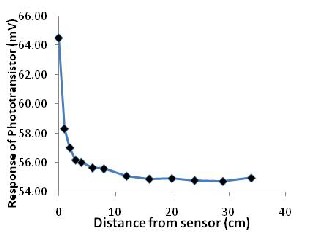
Fig 4.1: Response of Phototransistor 1 to varying light intensity
Fig 4.2: Response of phototransistor 2 to varying light intensity.
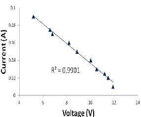
Fig 4.3: Response graph for the LDR
ER
Fig 4.4: LDR current voltage characteristics
IJSER © 2014 http://www.ijser.org
International Journal of Scientific & Engineering Research, Volume 4, Issue 12, December-2013 1728
ISSN 2229-5518
Fig 4.5: In (α)(attenuation) vs bend diameter (cm) for
SMF
Fig 4.6: In (α)(attenuation) vs bend diameter for MMF
The current voltage characteristics of the LDR are shown in Figure 4.4. There is a direct linear relationship between the voltage and current flowing through the LDR for the varying intensity values. This verifies Ohm’s law which states that the electric current (I) flowing through a conductor is directly proportional to the potential difference (V) between its ends, that is V = IR.
The attenuation value for the Single mode fibre when it
was straight = 926 dB/km. The attenuation value is very big
compared to other values obtained for example, 2.26 ×
10−2 dB/m which translates to 22.6 dB/km for wavelength
range 366-578 nm mercury vapour lamp light [3]. The
extremely high value of attenuation can be accounted for by
the low coupling efficiency of light into the optic fibre. Points
of measurement of input power into the optic fibre could not be precisely determined and this could have contributed in a higher value of input intensity than the actual intensity getting into the fibre.
Attenuation values for the multimode fibre were
extremely high. For straight condition of the fibre, attenuation
= 8732.21 dB/km for the multimode which is approximately
10 times the value for single mode fibre. However there was
little variation in the attenuation coefficient with change in
bending diameter.
For the single mode case, the power loss due to
macrobending increases exponentially as the bend diameter increases as seen by the almost linear graph of ln α (attenuation) versus the bend diameter, Figure 4.5 with an R2 value = 0.857. No significant trend can however be specified for the multimode, Figure 4.6 shows a close to constant variation of attenuation with bend diameter with the values for ln α oscillating between 9.14 and 9.20 dB/km.
From Figure 4.7 it can be deduced that attenuation is more pronounced in multimode fibres than it is single mode fibres. Characteristic values of attenuation for the optic fibre for example for bend diameter 10.02cm are 1466.13 dB/km for single mode compared to 9316.56 dB/km for multimode fibre. This is in agreement with theory where in single mode fibre, because of the small core and single light wave (mode) any distortion that could arise from overlapping modes is eliminated and hence the single mode provides the least signal attenuation [10]. Extra transmission loss is introduced
Fig 4.7: Comparison of Macrobend losses in SMF and
MMF
Figure 4.3 is a response graph for the LDR to varying light intensity. The LDR showed a linear variation with intensity swinging from negative to positive voltage. The readings were spread over a wider range compared to that of the detector circuit using phototransistors with values ranging from -2 to 6V. The light detector using LDR was therefore adopted for use as the light detector in this experiment.
in multimode fibres due to their nature where light propagates in several modes. The various modes of light introduce modal dispersion where the different modes of light arrive at the receiving end of the fibre at different times causing a spreading effect. There is also mode coupling and leaky modes being more prevalent in multimode fibre contributing to further attenuation described in section 2.6.3.
The power loss as a consequence of macrobending is
extremely low in the MMF and was difficult to quantify
experimentally. Kauffman et al [12] highlight the same effect
and instead assume a simple hypothesis about the
distribution of power among the modes where obtained results are used to analyse the trend of the overall loss of the
IJSER © 2014 http://www.ijser.org
International Journal of Scientific & Engineering Research, Volume 4, Issue 12, December-2013 1729
ISSN 2229-5518
multimode fibre with the radius of curvature. The general trend for the SMF was such that the attenuation increased with decrease in the bending diameter. For larger bend diameters the attenuation was tending to become constant suggesting the contribution of macrobending to the overall attenuation at this point was therefore minimal.
The major contributors of attenuation for larger and larger
bend diameters would be absorption, scattering and other
loss mechanisms. The result conforms to findings by other authors [3], [12], [13], [17]. The wavelength used in this experiment also contributed to more attenuation in the optic fibres as it is not the optimum or operational wavelength for either of the fibres.
5 CONCLUSION AND RECOMMENDATIONS
The research sought to investigate and compare the attenuation in Single Mode Fibre (SMF) and Multimode Fibre (MMF) due to macrobending. In order to do so improvisions were done for the light source using 555 timer astable multivibrator powering a green LED and an LDR in a Wheatstone bridge circuit that served as a light detector and optic fibres off-cuts used for the carrying out of the
meter for example an OTDR or Optical spectral Analyser. Further improvements would also include use of a proper optical bench using the specified operational light sources for the optic fibres that is LED for multimode fibre and laser for single mode fibre.
5.1 Recommendations
For further work it is recommended that the same work be done at operational wavelengths of the optic fibres using the ideal light sources for each of the fibres. Comparison would be easier if this is done at wavelength 1310 nm/1300 nm common and almost equal for both of the optical fibres. It would also be of great importance if the bend diameter could be lowered a bit more so as to ascertain how much more the fibres can bend before reaching the critical radius (diameter) that is the radius (diameter) beyond which the attenuation will rapidly increase.
Of interest would be also investigating and characterising
the macrobending attenuation trend for the recently
introduced plastic optic fibre (POF). The combination of this
with other factors like cost, transmission speed and
bandwidth would enable selection of any of these three for use such as to minimise cost yet not compromising on signal
experiment.
IJSEquality and Rstrength which is the main thrust of the
When there was no macrobending in both of the fibres
attenuation was recorded, the attenuation is associated with
scattering and absorption and other loss mechanisms. Overally signal power loss was higher in MMF than in SMF as seen in Figure 4.7 and this explains the reason why single mode fibre are usually preferred for long distance transmission. The loss in SMF without macrobending was found to be 926 dB/km and that for MMF to be 8732.21 dB/km.
Attenuation in the SMF increases as the bend diameter
decreases and does so in an exponential manner. It is a
different case for the MMF, where the attenuation trend
seemed not existant and was difficult to quantify. However from the results it can be deduced that single mode fibres are more susceptible to macrobending than multimode fibres. For instance the single mode has attenuation due to macrobending only for bending diameter 4.19 cm equal to
1268 dB/km while the multimode fibre has attenuation due to macrobending only equal to 1155 dB/km.
The results confirm that macrobending has a significant contribution to the overall attenuation in an optic fibre particularly in the SMF, hence it is important that macrobending be considered and characterised for efficient
signal transmission without compromise to quality.
Precautions were observed in order to minimise
inconsistencies in the carrying out of the experiment and
improve in the accuracy of the results. Some errors could not
be completely eliminated. More accurate determination of
attenuation in the optic fibres in this research could be achieved by using a more standard and sensitive optical
telecommunication industry.
REFERENCES
[1] H. J. R. Dutton, Understanding Optical Communications, International
Technical Support Organisation, 1998.
[2] N. Massa, Fundamentals of Photonics module, (Fiber Optic
Telecommunication), University of Connecticut, 2000.
[3] J Koning, R. N. Rieben, and G H. Rodrigue , Vector Finite-Element Modeling of the Full-Wave Maxwell Equations to Evaluate Power Loss in Bent Optical Fibers, Journal of Lightwave Technology, Dec 2005
[4] A. Bakar, MZ Jamaladin, F Abdullah, A new technique of real-time monitoring of fibre Optic cable networks transmission Optics and Lasers in Engineering, 2007.
[5] Y. Chigusa, Y.Yamamoto, T. Yokokawa, T. Sasaki, T. Taru, M. Hirano, M.
Kakui, M. Onishi, and E.Sasaoka, Low-Loss Pure-Silica-Core Fibers and their Possible Impact on Transmission Systems, Journal of Lightwave Technology, Vol. 23, Issue 11, pp. 3541- (2005).
[6] D. Marcusse, Losses and Impulse Response of a Parabolic Index Fiber with Random Bends, The. Bell Systems. Technical Journal, 1973.
[7] P. Wang, Q. Wang, G. Farrell, G. Rajan, T. Freir, J. Cassidy. Investigation of macrobending losses of standard single mode fiber with small bend radii Microwave and Optical Technology Lectures, (2007).
[8] W. B. Gardner, Microbending Loss in Optical Fibres, The. Bell Systems.
Technical Journal, 1974.
[9] John A.Jay, An overview of Macrobending and Microbending of Optical
Fibers. White paper Corning incorporated , December 2010.
[10] K. Witcher, Fiber Optics and Its Security Vulnerabilities, White paper
SANS Institute, University MARY Washington, 2005.
[11] G. Getu, Experimental Technique to Characterize Macrobending Loss in
IJSER © 2014 http://www.ijser.org
International Journal of Scientific & Engineering Research, Volume 4, Issue 12, December-2013 1730
ISSN 2229-5518
Single Mode Fiber, Masters Thesis, Addis Ababa University, 2010.
[12] K.S. Kaufman, R. Terras and R.F. Matthis, Curvature Loss in Multimode
Optic Fibres, Journal of Optical Society of America, 1981.
[13] D. Bernhard and D. R. Velasquez, Bending Over Backwards, Corning, OSP Magazine, 2007.
[14] A. Zendehnam, M. Mirzaei, A. Farashiani and L.H. Farahani, Investigation of bending loss in a single-mode optical fibre. Prama Journal of Physics, Indian Academy of Sciences, (2009).
[15] S. R. Bickham, S. C. Garner, O. Kogan and T. A. Hanson, Theoretical and Experimental Studies of Macrobend losses in Multimode fibers, International Wire and Cable Symbosium, Proceedings of the 58th IWCS.
[16] D. Molin, P. Matthijsse, G. Kuyt and P. Sillard, Reduced Bend Sensitivity of Multimode Fibers in Fttx applications. In proceeding of: Optical Fiber Communication (OFC) collocated National Fiber Optic Engineers Conference, 2010.
[17] H. J. Patrick, A. D. Kersey, and F. Bucholtz, Analysis of the Response of Long Period Fiber Gratings to External Index of Refraction, Journal of Lightwave Technology, Vol. 16, Issue 9, pp. 1606- (1998).
IJSER
IJSER © 2014 http://www.ijser.org