International Journal of Scientific & Engineering Research, Volume 3, Issue 11, November-2012 1
ISSN 2229-5518
Comparison of Block Type Pilot Channel Estimation
Techniques for Evaluating the performance of OFDM
Keshav Kumar, Amit Grover
Abstract
With the rapid growth of digital communication in recent years, the need for high speed data transmission is increased. Moreover, future wireless systems are expected to support a wide range of services which includes video, data and voice. OFDM is a technique for achieving high data rates in mobile environment, due to its resistance to ISI, which is a common problems found in high speed data communication. In OFDM, modulation may be differential or coherent. In this paper the channel estimation techniques for OFDM systems based on Block Type Pilot arrangement are investigated. The estimation of channel at pilot frequencies is based on LSE and MMSE. The channel estimation based on block type pilot arrangement is performed by sending pilots at every sub-channel and using this estimation for a specific number of following symbols. I have compared the performances of all schemes by measuring bit error rate by using 16QAM, QPSK, and BPSK. We have found that BER performance of Block type pilot estimation using BPSK modulation have best performance. We also compare the LSE and MMSE we calculated that MMSE Block type pilot channel estimation technique have the better BER performance than LSE.
Keywords: Orthogonal-frequency-division-multiplexing (OFDM), Quadrature Amplitude Modulation (QAM), Quadrature Phase Shift Key (QPSK), Binary Phase Shift Key (BPSK), Intersymbol Interference (ISI), Inter Channel Interference (ICI), Linear Minimum mean-squared error (LMMSE), Least Square Error (LSE), Time Division Multiplexing(TDM).
1. Introduction to OFDM
------------------------ ------------------------
allows transmission of multiple information signals over a
Orthogonal frequency division multiplexing (OFDM) is based on multicarrier communication techniques. The idea of multicarrier communications is to divide the total signal bandwidth into number of subcarriers and information is transmitted on each of the subcarriers. Unlike the conventional multicarrier communication scheme in which spectrum of each subcarrier is non- overlapping and band-pass filtering s used to extract the frequency of interest, in OFDM the frequency spacing between subcarriers is se le ct e d such that the subcarriers are mathematically orthogonal to each others. The spectra of subcarriers overlap each other but individual subcarrier can be extracted by baseband processing. This overlapping property makes OFDM more spectral efficient than the conventional multicarrier communication scheme.
A further advantage of OFDM is that because the
symbol period has been increased, the channel delay spread is significantly a shorter fraction of a symbol period than in the serial system, potentially rendering the system less sensitive to ISI than the conve ntional serial system.
Disadvantage of the OFDM a p p r o a c h , is the
increased complexity over the conventional system caused by employing modulators a n d f i l t e r s at the transmitter and demodulators and filters at the receiver.
1.1 Othogonality in OFDM
signal channel by assigning unique time slots to each spate information signal. During each time slot only the signal from a single source is transmitted preventing any interference between multiple information sources. Because of this TDM is orthogonal in nature. In the frequency domain most FDM systems are orthogonal as each of the separate transmission signals are well spaced out in frequency preventing interference. Although these methods are orthogonal the term OFDM has been reserved for a special form of FDM. The subcarriers in an OFDM signal are spaced as close as is theoretically possible without maintaining orthogonality between them.
OFDM achieves orthogonality in the frequency domain by allocating each of the separate information signals onto different sub carriers. OFDM signals are made up of sum of sinusoids, with each corresponding to a subcarrier. The baseband frequency of each subcarrier is chosen to be an integer multiple of the inverse of the symbol time, resulting in all subcarriers having an integer number of cycles per symbol.
Since the carriers are all sine/cosine wave, we know that area under one period of a sine or a cosine wave is zero. Let’s take a sine wave of frequency m and multiply it by sinusoid of a frequency n, where both m and n are integers. The integral or the area under this product is given by
Signals are orthogonal if they are mutually independent of each other. Orthogonality is a property that allows multiple information signals to be transmitted perfectly over a common channel and detected, without interference. Loss of orthogonality results in blurring between these information signals and degradation in communications. Many common multiplexing schemes are inherently orthogonal. Time division multiplexing (TDM)
�(�) = �𝑖� �(��)��𝑖� �(��) (1)
By the simple trigonometric relationship, this is equal to a
sum of two sinusoids of frequencies (n-m) and (n + m)
�(�) = ½𝑐�� (� − �) − ½𝑐��(� + �) (2)
These two components are each a sinusoid, so the integral
is equal to zero over one period
IJSER © 2012 http://www.ijser.org
International Journal of Scientific & Engineering Research, Volume 3, Issue 11, November-2012 2
ISSN 2229-5518
2𝜋
�(�) = ∫ ½𝑐�� (� − �)��
0
(3)
multiple carrier scheme using a bank of parallel modulators would not be very efficient in analog hardware. However,
2𝜋
− ∫ ½𝑐��(� + �) �� = 0
0
We conclude that when we multiply a sinusoid of
frequency n by a sinusoid of frequency m/n, the area under
the product is zero. These frequencies are called harmonics
This idea is served as key to understand OFDM. The
orthogonality allows simultaneous transmission on a lot of
sub-carriers in a tight frequency space without interference from
1.2 Basic Principle of OFDM
At the transmitter side, the binary information is first
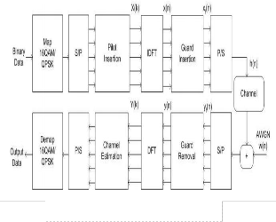
grouped and mapped into complex-valued symbols according to the modulation by different mapping scheme, such as BPSK, QPSK, 16QAM, and 64QAM. Then there is a serial to parallel conversion to prepare different data groups for different OFDM subcarrier. The mapped signals are modulated into N orthogonal subcarrier by the IFT. A cyclic prefix (CP) is then added to the multiplexed IFFT output. Finally, the obtained signal is converted to a time continuous analog signal before it is transmitted through the channel. At the receiver side, an inverse operation is carried out and the information data is detected. OFDM is a modulation technique where multiple low data rate carriers are combined by a transmitter to form a composite high data rate transmission. Digital signal processing makes OFDM possible. To implement the multiple carrier schemes using a bank of parallel modulators would not be very efficient in analog hardware. However, in the digital domain, multi-carrier modulation can be done efficiently with currently available DSP hardware and software. Not only can it be done, but it can also be made very flexible and programmable. This allows OFDM to make maximum use of available bandwidth and to be able to adapt to changing system requirements.
Each carrier in an OFDM system is a sinusoid with a
frequency that is an integer multiple of a base
or fundamental sinusoid frequency. Therefore, each carrier is like a Fourier series component of the composite signal. In fact, it will be shown later that an OFDM signal is created in the frequency domain, and then transformed into the time domain via the Discrete Fourier Transform (DFT).Two periodic signals are orthogonal when the integral of their product, over one period, is equal to zero.
OFDM is a modulation technique where multiple low data rate carriers are combined by a transmitter to form a composite high data rate transmission. Digital signal processing makes OFDM possible. To implement the
in the digital domain, multi-carrier modulation can be done
efficiently with currently available DSP hardware and
software. Not only can it be done, but it can also be made very flexible and programmable. This allows OFDM to make maximum use of available bandwidth and to be able to adapt to changing system.
Figure.1 OFDM Block Diagram.
1.3 Importance of Othogonality in OFDM
The “orthogonal” part of OFDM name indicates that there is a precise mathematical relationship between the frequencies of the carriers in the system. In a normal FDM system, the many carriers are spaced apart in such way that the signals can be received using conventional filters and demodulators. In such receivers, guard bands have to be introduced between the different carriers and the introduction of these guard bands in the frequency domain results in lowering of the spectrum efficiency. It is possible, however to arrange the carriers in an OFDM signal so that the sidebands of the individual carriers overlap and the signals can still be received without adjacent carrier receiver acts as a bank of demodulators, translating each carrier down to DC, the resulting signal then being integrated over a symbol period(t) to recover the raw data. If the other carriers all beat down to frequencies which in the time domain have a whole numbers of cycles in the symbol period, then the integration process results in zero contribution from all these carriers. Thus the carriers are linearly independent if the carrier spacing is a multiple of 1/t
1.4 Generation of OFDM Symbols
A baseband OFDM symbol can be generated in the digital domain before modulating on a carrier for transmission. To generate a baseband OFDM symbol, a serial digitized data stream is first modulated using
IJSER © 2012 http://www.ijser.org
International Journal of Scientific & Engineering Research, Volume 3, Issue 11, November-2012 3
ISSN 2229-5518
common modulation schemes such as the phase shift keying (PSK) or quadrature amplitude modulation (QAM). These data symbols are then converted to parallel streams before modulating subcarriers. Subcarriers are sampled with sampling rate N/Ts, where N is the number of subcarriers and Ts is the OFDM symbol duration. The frequency separation between two adjacent subcarriers is 2π/N. Finally, samples on each subcarrier are summed together to form an OFDM sample. An OFDM symbol generated by an N -subcarrier OFDM system consists of N samples and the m- th sample of an OFDM symbol is given
�=1
1.5 Intersymbol and Intercarrier Interference
In a multipath environment, a transmitted symbol takes different times to reach the receiver through different propagation paths. From the receiver’s point of view, the channel introduces time dispersion in which the duration of the received symbol is stretched. Extending the symbol duration causes the current received symbol to overlap previous received symbols and results in intersymbol interference (ISI).
In OFDM, ISI usually refers to interference of an
OFDM symbol by previous OFDM symbols. In
�� = ∑ �
�=1

𝑗2𝜋��
�
�� �ℎ��� 0 ≤ � ≤ 𝑁 − 1
(4)
OFDM, the spectra of subcarriers overlap but remain
orthogonal to each other. This means that at the maximum of each subcarrier spectrum, all the spectra of other subcarriers are zero. The
Where �� is the transmitted data symbol on the nth
carrier. Equation (1) equivalent to the N point inverse
discrete Fourier transform (IDFT) operation on the data sequence with the omission of a scaling factor.
IDFT can be implemented efficiently using Inverse Fast Fourier Transform (IFFT). Therefore, in practice, the IFFT is performed on the data sequence at an OFDM transmitter for baseband modulation and the FFT is performed at an OFDM receiver for baseband demodulation. Size of FFT and IFFT is N, which is equal to the number of sub channels available for transmission, but all of the channels needs to be active. The sub-channel bandwidth is given by
receiver samples data symbols on individual subcarriers at the maximum points and demodulates them free from any interference from the other subcarriers. Interference caused by data symbols on adjacent subcarriers is referred to intercarrier interference (ICI).
1.6 Guard Time Insertion
OFDM is resilient to ISI because its symbol duration is long compared with the data symbols in the serial data stream. For an OFDM transmitter with N subcarriers, if the duration of a data symbols is T’, the duration of the OFDM symbols at the output of the transmitter is

1
��� = =
�

��𝑎��
𝑁
(5)
�� = �′𝑁 (6)
Thus if the delay spread of a multipath channel is greater
Where ��𝑎�� the sample is rate and �� is the sample time.
Finally, a baseband OFDM symbols is modulated by
a carrier to become a band-pass signal and transmitted to
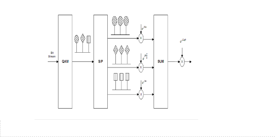
the receiver. In the frequency domain, this corresponds to translating all the subcarriers from baseband to the carrier frequency simultaneously. Figure. 1 shows a 3-subcarier OFDM transmitter and the process of generating one OFDM symbol.
than �′ but less then ��
The data symbols in the serial data stream will
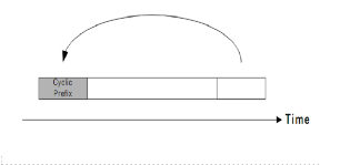
experience frequency-selective fading while the data symbols on each subcarrier will experience only flat - fading. Moreover, to further reduce the ISI, a guard time is inserted at the beginning of each OFDM symbols before transmission as shown in Figure 3 and removed at the receiver before the FFT operation.
In order to avoid ISI and ICI, the guard period must be formed by a cyclic extension of the symbol period. This is done by taking symbol period samples from the end of the period and appending them to the front of the period. The concept of being able to do this, and what it means, comes from the nature of the IFFT/FFT process. When the IFFT is taken for a symbol period (during OFDM modulation), the resulting time sample sequence is technically periodic. This is because the IFFT/FFT is an extension of the Fourier Transform which is an extension of the Fourier series for periodic waveforms. All of these transforms operate on signals with either real or manufactured periodicity. For the IFFT/FFT, the period is the number of samples used.
Figure.2 3-subcarier OFDM transmitter and the process of generating one OFDM symbol.
IJSER © 2012 http://www.ijser.org
International Journal of Scientific & Engineering Research, Volume 3, Issue 11, November-2012 4
ISSN 2229-5518
delay spread is decreased. ISI is almost eliminated completely by introducing a guard interval (GI) in every OFDM symbol. In the guard time, the OFDM symbol is cyclically extended to avoid ICI. This whole process of generating an OFDM signal and the preliminary concepts such as series-to parallel converter.

Figure3. Guard Time Insertion
If the guard time is chosen such that its duration is longer than the delay spread, the ISI can be completely eliminated.
In order to preserve orthogonality among subcarriers, the guard time is inserted by cyclically extending an OFDM symbol. Guard time insertion can be introduced in many ways, but the most effective way of inserting guard period is to extract a portion of an OFDM symbol at the end and append it to the beginning of the OFDM symbol.
2. Introduction to Channel Estimation
A dynamic estimation of channel is necessary before the demodulation of OFDM signals since the radio channel is frequency selective and time-variant for wideband mobile communication systems. The channel estimation can be performed by either inserting pilot tones into all of the subcarriers of OFDM symbols with a specific period or inserting pilot tones into each OFDM symbol. The first one, block type pilot channel estimation, has been developed under the assumption of slow fading channel. Even with decision feedback equalizer, this assumes that the channel transfer function is not changing very rapidly. The estimation of the channel for this block-type pilot arrangement can be based on LS or MMSE. The MMSE estimate has been shown to give 10-15 dB gain in SNR for the same mean square error of channel estimation over LS estimate. A low-rank approximation is applied to linear MMSE by using the frequency correlation of the channel to eliminate the major drawback of MMSE, which is complexity.
Channel estimation is the task of estimating the
frequency response of the radio channel which the transmitted signal travels before reaching the receiver antenna. In wideband wireless communication Systems, especially in the mining environment, the channel is usually frequency selective and time variant and the channel transfer function appears unequal in both frequency and time domains. Therefore, dynamic channel estimation is necessary for the demodulation of OFDM signals.
In OFDM Systems, the high-rate data stream is split
into a number of lower rate streams that are transmitted simultaneously over a number of subcarriers. Because the symbol duration increases for the lower rate parallel subcarriers, the relative amount of dispersion in time caused by multipath
Figure4. Effect of a fades on serial and parallel system
There are two main problems in designing channel estimators for wireless OFDM systems. The first problem is the arrangement of pilot information, where pilot means the reference signals used by both transmitter and receiver. The second problem is the design of an estimator with both low complexity and good tracking ability. The two problems are interconnected. In general, the fading channel of OFDM system can be viewed as a two dimensional (2D) signal (time and frequency).
2.1 Channel estimation in OFDM classification
There are basically two types of classification of Channel estimation in OFDM
Pilot Based Channel Estimation: Known symbol
called pilots are transmitted.
Blind Channel Estimation: No pilots required. It uses some underlying mathematical properties of data sent.
In this paper we are going to study BER performance evaluation of Pilot Based Channel estimation in OFDM.
The Blind channel estimation methods are computationally complex and hard to implement. The Pilot based channel estimation methods are easy to implement but they reduces the bandwidth efficiency. The Pilot based methods are most popular now a days. IEEE 802.16e, 3GP LTE standards support the pilot based channel estimation.
There are mainly two problems in the design of
channel estimators for the wireless systems. The first
IJSER © 2012 http://www.ijser.org
International Journal of Scientific & Engineering Research, Volume 3, Issue 11, November-2012 5
ISSN 2229-5518
problem is concerned with the choice of how the pilot information should be transmitted. Pilot symbols along with the data symbols can be transmitted in a number of ways, and different patterns yields different performances. The second problem is the design of an interpolation filter with both low complexity and good performance. These two problems are interconnected, since the performance of the interpolator depends on how pilot information is transmitted. In general, some pilot signals are inserted as a reference for OFDM channel estimation and whole one OFDM frame is often used as a pilot frame. Focusing on the one dimensional estimation based on pilot insertion, we follow mainly block pilot insertion, comb pilot insertion without forgetting those used on two dimensional estimation.
Channel estimation methods based on the pilot insertion can be divided into two classical pilot models, which are block-type and comb-type model. The first
estimated by interpolations. However, in single carrier case, the pilot patterns should be designed so that the channel oversampled at the receiver.
2.1.2 Block Type Pilot based channel estimation
In this type, OFDM symbols with pilots at all
subcarriers (referred to as pilot symbols herein) are transmitted periodically for channel estimation. Using these pilots, a time-domain interpolation is performed to estimate the channel along the time axis. Let
�� denote the period of pilot symbols in time. In order to
keep track of the time-varying channel characteristics, the
pilot symbols must be
placed as frequently as the coherence time is. As the
coherence time is given in an inverse form of the Doppler
frequency �������� in the channel. The pilot symbol period
must satisfy the following Inequality:
1
model refers to that the pilots are inserted into all the
subcarriers of one OFDM symbol with a certain period. The
block -type can be adopted for slowly fading channel, that is, the channel can be considered as stationary within a certain period of OFDM symbols. Nevertheless, the second model refers to that the pilots are positioned at some definite subcarriers in each OFDM symbol. In this paper we are going too implemented only block type pilot based channel estimation in OFDM.
�� ≤

��������
2.1.1 Pilot Symbol Assisted Modulation
Channel estimation usually needs some kind of pilot information as a point of reference. Channel estimates are often achieved by multiplexing known symbols, so called, pilot symbols into the data sequence, and this technique is called Pilot Symbol Assisted Modulation (PSAM). This method relies upon the insertion of known phase into the stream of useful information symbols for the purpose of channel sounding. These pilot symbols allow the receiver to extract channel attenuations.
and phase rotation estimates for each received symbol,
facilitating the compensation of fading envelope and
phase. Closed form formula for the BER of PSAM were provided by Cavers for binary phase shift keying (BPSK) and quadrature phase shift keying (QPSK), while for 16- QAM he derived a tight upper bound of the BER.
A fading channel requires constant tracking, so
pilot information has to be transmitted more or less continuously. Decision directed channel estimation can also be used, but even in these types of schemes pilot information has to be transmitted regularly to mitigate error propagation. Pilot symbols are transmitted at certain locations of the OFDM frequency time lattice, instead of data and it was addressed how you choose those locations. In general fading channel can be viewed as a 2-D signal (time and frequency), which is sampled at pilot positions and channel attenuations between pilots are
Figure5. Block Type Channel Estimation
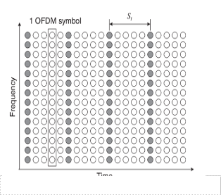
Since pilot tones are inserted into all subcarriers of pilot symbols with a period in time, the block type pilot arrangement is suitable for frequency-selective channels. For the fast-fading channels, however, it might incur too much overhead to track the channel variation by reducing the pilot symbol period.
2.1.3 Block Type pilot signal estimation
Channel can be estimated at pilot frequencies by two ways:
(LS) Estimation
(LMMSE) Estimation
For block type arrangements, channel at pilot tones can be estimated by using LS or LMMSE estimation, and assumes that channel remains the same for the entire block. So in block type
IJSER © 2012 http://www.ijser.org
International Journal of Scientific & Engineering Research, Volume 3, Issue 11, November-2012 6
ISSN 2229-5518
estimation, we first estimate the channel, and then use the same estimates within the entire block.
minimum mean square error estimate for this problem is given by
LMMSE estimation has been shown to yield 10-12dB gain
−1
𝐻���𝑆𝐸 = �ℎ� (��� )
� (8)
in signal to noise ratio (SNR) over LS estimation for the
same mean square error of channel estimation. A low rank approximation is applied to linear MMSE by using the frequency correlations of the channel to eliminate the major drawback of MMSE, namely complexity.
Where �ℎ� is the cross-covariance matrix between h and the
noisy pilot estimates p, given by
�ℎ� = �{ℎ�𝐻 } (9) Where ��� is the auto-covariance matrix of the pilot
estimates, and is given by
��� = �{��𝐻 } (10)
2

Where 𝜎� is the variance of the additive channel noise. The
superscript (. )𝐻 denotes Hermitian transpose.
= ��� + 𝜎 2 (��
𝐻 )−1
(11)
Now for the case of block-type pilot channel estimation,
𝐻 = � {� + 𝜎 2(��𝐻 )−1 }−1�
(12)
3. Simulation and Results
Figure6. Pilot signals inserted in Block Type
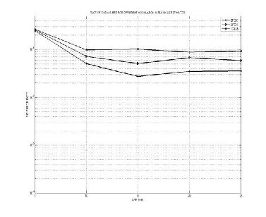
2.1.3.1 Least Square Estimation (LSE)
The idea behind least squares is to fit a model to measurements in such a way that weighted errors between the measurements and the model are minimized. The LS estimate of the attenuations h, given the received data Y and the transmitted symbols X is:
In this paper, we used MATLAB 7.0 software for simulation for the Bit Error Rate (BER) performance of the different modulation techniques like BPSK and QPSK and
16QAM.
Figure.7 shows the least square estimation in block type and the BER performance of Block type pilot estimation using BPSK modulation has the best performance.
𝐻�𝑆 = �−1� = [

�0 �1
�0 �1
… … … … … … . .

��−1
��−1
] (7)
2.1.3.2 Linear Minimum Mean Square Error Estimation
The linear minimum mean square error (LMMSE) estimate has been shown to be better than the LS estimate for channel estimation in OFDM systems based on block type pilot arrangement. The LMMSE estimate has about 10-15dB gain in SNR over LS estimate for the same MSE values. The major drawback of the LMMSE estimate is its high complexity, which grows exponentially with observation samples. In a low rank approximation is applied to a linear minimum mean squared error estimator (LMMSE estimator) that uses the frequency correlations of the channel.
Assume that all the available LS estimates are
arranged in a vector p and the channel values that have to
be estimated from p are in a vector h. The channel estimation problem is now to find the channel estimates h as a linear combination of pilot LS estimates p. The
Figure 7. Least Square Estimation in block
Figure.8 shows the Minimum mean square error estimation
IJSER © 2012 http://www.ijser.org
International Journal of Scientific & Engineering Research, Volume 3, Issue 11, November-2012 7
ISSN 2229-5518
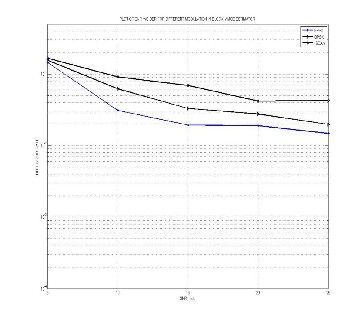
in block type and the BER performance of Block type pilot estimation using BPSK modulation has the best performance.
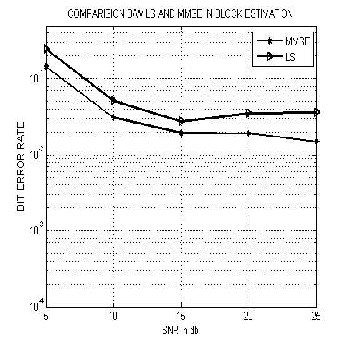
Figure 9. Comparisons between LS and MMSE in Block
Estimation
type
Figure 8. Minimum Mean Square Error in block
Further the simulation results for OFDM with BPSK over AWGN have also been shown in the Figure.10 by considering the different parameters as shown in the Table
1.
Figure.9 shows the comparison between LS and MMSE in block Estimation. It has been observed that Minimum mean square error block type pilot channel Estimation has the better BER performance than the LSE.
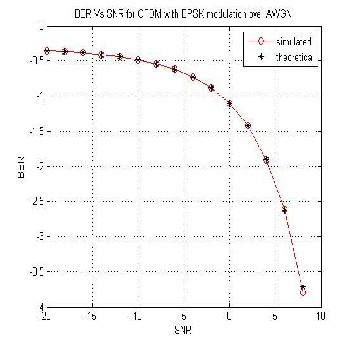
Figure10. BER Vs SNR for OFDM with BPSK over
AWGN
IJSER © 2012 http://www.ijser.org
International Journal of Scientific & Engineering Research, Volume 3, Issue 11, November-2012 8
ISSN 2229-5518
[5] H. Minn and V. K. Bhargava(2000), "An Investigation into Time-Domain Approach for OFDM Channel Estimation" IEEE Trans. on Broadcasting, Vol. 46, No. 1, pp.
240-248.
[6] M. Morelli and U. Mengali (2001), "A comparison of Pilot-Aided Channel Estimation Methods for OFDM Systems," IEEE Trans. on Signal Processing, Vol. 49, No. 12, pp. 3065-3073.
[7] P.-Y. Tsai and T. -D. Chiueh (2004), "Frequency-Domain Interpolation-Based Channel Estimation in Pilot-Aided OFDM Systems," IEEE 59th Vehicular Technology Conference (VTC'04), Vol. 1, pp. 420-424, Milan, Italy.
Table.1 All Simulation Parameters
4. Conclusion
In this paper, Channel Estimation based on block type Pilot arrangement is presented and it is shown that this type of arrangement performs better when the channel is changing slowly. The estimation of channel at pilot frequencies is based on LSE and MMSE. The channel estimation based on block type pilot arrangement is performed by sending pilots at every sub-channel and using this estimation for a specific number of symbols. I have compared the performances of all schemes by measuring bit error rate by using 16QAM, QPSK, and BPSK. We have found that BER performance of Block type pilot estimation using BPSK modulation has the best performance and in the comparison of LSE and MMSE we calculated that MMSE Block type pilot channel estimation technique has the better BER performance than LSE.
5. References
[1] T.S.Rappaport (2009), “Wireless Communication”,
Prentice Hall.
[2] M. Hsieh and C. Wei (2002), “Channel estimation for OFDM systems based on comb-type pilot arrangement in frequency selective fading channels” in IEEE Transactions on Consumer Electronics, vol. 44.
[3] S. Coleri, M. Ergen, A. Puri and A. Bahai (2002), “Channel estimation techniques based on pilot arrangement in OFDM systems,” IEEE Trans. On Broadcasting, Vol. 48, No.3.
[4] IEEE 802.11 Standard, “Wireless LAN Medium Access
Control (MAC) and Physical Layer (PHY) specifications,”
1999.
[8] A. Benzakour, S. Affes, C. Despins, and P.-M. Tardif (2004), "Wideband Measurements of Channel Characteristics at 2,4 and 5.8 GHz in Underground Mining Environments," Proc.of IEEE VTC'04-Fall, Los Angeles, California, USA, Vol. 5, pp. 3595-3599.
[9] M. Boutin (2004), “Statistical Modeling of a Radio Propagation Channel in an Underground Mine at 2.4 GHz and 5.8 GHz,” Master's Thesis, INRS-EMT, Montréal, Canada.
[10] R. Steele (1992), “Mobile Radio Communications,”
London, England, Pentech Press Limited.
[11] J. Heiskala, J. Terry (2002), “OFDM Wireless LANs: A Theoretical and Practical Guide,” Sams Publishing.
[12] C. Nerguizian, M. Djadel, C. Despins, and S. Affes (2003), "Narrowband and Wideband Radio Channel Characteristics in Underground Mining Environments at
2.4 GHz, " Proc. of IEEE PIMRC'03, Beijing, China, Vol. 1,
pp. 680-684.
[13] Yong Soo Cho, Won young Yang, “MIMO-OFDM Wireless communication With Matlab”.
[14] Y. Li (2000), “Pilot-Symbol-Aided Channel Estimation for OFDM in Wireless Systems”, in IEEE Transactions on Vehicular Technology, vol. 49, no.4.
[15] Uma Shanker Jha, “OFDM Towards fixed and Mobile broadband wireless Access”.
[16] D. J. Young and C. Beaulieu (2000), “The generation of correlated Rayleigh random variates by inverse discrete Fourier transform,” IEEE Trans . on Communications , Vol.
48, No. 7.
[17] R. Prasad (2004), “OFDM for Wireless Communications
Systems,” Artech House, Boston- London.
[18] T. Roman, M. Enescu, and V. Koivunen (2003), "Time-
IJSER © 2012 http://www.ijser.org
International Journal of Scientific & Engineering Research, Volume 3, Issue 11, November-2012 9
ISSN 2229-5518
domain method for tracking dispersive Channels in OFDM Systems," In Proc. of IEEE Veh. Technol. Conf., Vol.2, pp.
1318-1321.
[19] S. G. Kang, Y. M. Ha, and E. K. Joo (2003), "A comparative investigation on channel estimation algorithms for OFDM in mobile communications,'" IEEE Trans. on Broadcasting, Vol. 49, No. 2, pp. 142-149.
[20] R. Van Nee and R. Prasad (2000), “OFDM for Wireless Multimedia Communications, Artech House Publishers, Massachusetts.
[21] Richard Van Nee and Ramjee Prasad (2000), “OFDM for Wireless Multimedia Comunications. Artech House Publishers,”
[22] JAe Kyoung Moon and Song In Choi (2000),
“Performance of channel estimation methods for OFDM
systems in multipath fading channels,”IEEE Trans. of
Communication Electronics, vol. 46, pp. 161–170.
[23] Fredrik Tufvesson and Peter Hoeher (2000), “Channel Estimation using Superimposed Pilot Sequences,”IEEE Trans. on Communication.
[24] J.-J van de Beek, O. Edfors, M. Sandell, S.K. Wilson and P.O. Borjesson (1995), “ On channel estimation in OFDM systems” in Proc. IEEE 45th Vehicular Technology Conference, Chicago, IL, pp. 815-819.
[25] Jan-Jaap van de Beek. “On Channel Estimation in
OFDM Systems”.
[24] O. Edfors, M. Sandell, J.-J. van de Beek, S. K. Wilson and P. O. Borjesson (1998), "OFDM channel estimation by singular value decomposition" IEEE Trans. Commun, pp.
931-939.
AUTHOR’SBIOGRAPHY

Amit Grover (M’06-SM’09-PI’11&12 )The author became a Member (M) of Association ISTE in 2006, a Senior Member (SM) of society SELCOME in september 2009, and a Project-Incharge (PI) in august 2011 and in September
2012. The author place of birth is Ferozepur, Punjab, India
on 27th, September 1980.
The author received M.Tech degree in Electronics and
Communication Engineering from Punjab Technical
University, Kapurthla, Punjab, India in 2008 and received B.Tech degree in Electronics and Communication Engineering from Punjab Technical University, Kapurthala, Punjab, India in 2001. Currently, he is working as an Assistant Professor in Shaheed Bhagat Singh State Technical Campus, Ferozpur, Punjab, India. The email-id of corresponding author is amitgrover_321@rediffmail.com and his contact number is +91-9988168581. His area of interest includes signal processing, mimo systems, wireless mobile communication, high speed digital communications and 4G wireless communications.
IJSER © 2012 http://www.ijser.org