International Journal of Scientific & Engineering Research, Volume 2, Issue 12, December-2011 1
ISSN 2229-5518
Comparative Simulation of MBIST using March- Test Algorithms
Er.Manoj Arora, Er.Shipra Tripathi
Abstract- Memories are an important aspect as there is an growth in submicron technologies. Memories may be RAM, ROM, DRAM etc becomes difficult to test as the system complexity increases. These embedded memories are on SOCs in which the embedded RAM memory is very hard to test because its testing needs a large number of pattern stimuli to be delivered to memory and retrieving a huge data. So time factor and difficulty forces us to use Memory BIST. BIST implies Built In Self Test,is a design technique in which,parts of circuits is use to test the circuit itself. In memory BIST,memory testing algorithms are implemented on chip which are faster than the conventional memory testing. March test algorithms are suitable for memory testing because of its regularity in achieving high fault coverage. This paper discussed about Memory BIST by applying march algorithm.
Index Terms- BIST, MBIST, Memory faults, Memory Testing.
1 INTRODUCTION
—————————— ——————————
In this new era, system complexity increase, as in turn embedded memories has become very important factor having intake of very large area on soc’s[1]. When this complex circuit is placed on soc’s with great care then also defects and faults arises. Sometimes they do not recognize during fabrication process . Hence there is some algorithms that we apply to reduce these defects and faults to improve the quality of system but time and cost are also the important factors that we must have to remember.
2 HISTORY
BIST is better replacement of ATE. BIST is basically Built In
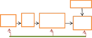
Self Test means part of circuit is use to test the circuit itself. There is no need of external tester as we needed in case of ATE which helps to make BIST inexpensive than ATE. BIST needs extra logic which in turn results increase in area overhead and show some degradation in performance. The schematic diagram of BIST is shown in Fig 1.
refrences
2.1 IC TESTING: Following two techniques are used for the
IC testing:-
source
cut
data compressor
compar ator
a) Through ATE (Automatic Test Equipment)
b) By applying BIST.
ATE is basically an external equipment that we use for testing by storing input vector and correct response data in ATE memory. TPG tools generate the input data whereas circuit simulation provides us the correct response data and both these data are compared by tester. In past, ATE dominates but as there is increase in complexity, there is a growing gap start existing between ATE capability and requirements
Er.Manoj Arora,HOD and Assistant Professor in Eectronics and communication,in JMIT,radaur,Kurukshetra University,INDIA. E-mail: mkumarmm@gmail.com.
Er.Shipra Tripathi is currently pursuing masters degree program in electronics and communication engineering in JMIT,radaur,Kurukshetra University, INDIA. E-mail: shipratripathi01@gmail.com
Start/stop ready
Fig 1. Basic BIST architecture
Start/Stop control line and the Random Pattern is supplied by the source which then fed to the data compressor and comparator. The start signal allocates with the very first pattern tells the data compressor to compress the output data or response until stop signal is not issued which acknowledges about the last random pattern. This stop signal also acknowledges the comparator to start comparing. For this purpose,we need an refrence signature in which the expected output is stored. This signature is matched or compared with the output response,if both are same,circuit passes the test.
Bist has the following advantages over ATE:-
IJSER © 2011
http://www.ijser.org
International Journal of Scientific & Engineering Research, Volume 2, Issue 12, December-2011 2
ISSN 2229-5518
1) No external test equipment
2) Reduces development efforts
3) Tests can run at circuit speed
4) Higher controllability and observability by On Chip
Test Pattern Generator
5) Response analysis on chip
6) On-Line and Off- Line test
7) Easier burn in support
8) Easily adaptable to engineering changes.
In integrated circuits Memory Faults have different behaviouring nature than other faults,so these faults can be removed or repaired by Functional Fault Models(FFM). Fault modelling in memory bist is a hard task to do. Adding an test circuitry to the memory itself is a solution provided by the Memory Bist.
block (2) Address decoder (3) R/W logic having different
structure and analysis method as shown in fig 3.[6].
Fig 3. Functional Fault Model (FFM)
Faults in Memory Array are defined as follows:-
Definition 1:- A memory cell is said to be stuck at if the logic value of the cell can not be changed by any action on the cell or by influences from other cells.
Definition 2:- A memory cell is said to be stuck open if it is not possible to access the cell by any action on the cell.
Definition 3:-A memory cell with a transition fault fails to undergo at least one of the transitions 01 or 10.
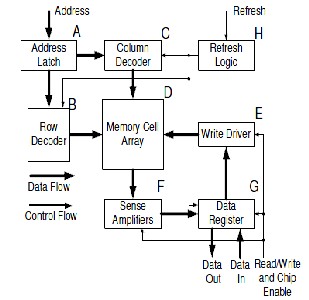
Fig 2. Generic MBIST architecture
Fig
Definition 4:- There is said to be data retention fault in a cell if
the cell fails to retain its logical value after some units of time.
Spot defects are also in memory cells because of extra contacts, shorts between wires, newly created transistors,
In Fig 2., there is Read/write data circuit, memory cell array and address-decoder logic together called as circuit under test. Memory Bist consist mbist controller, wrapper and the interconnections between the controller and the wrapper. These interconnections are of two types either serial or parallel.
2.2 FAULT MODELS
A FFM is a change in memory behaviour under the set of operations from the expected behaviour. Mainly functional fault models(FFM) are developed into (1) The memory array
broken wires, missing contacts.[6].
An inversion coupling fault involves two cells i and j; the fault is sensitised by a transition write operation to a particular cell j. Cell j is called the coupling cell and inverts the content of cell i, which is called the coupled cell.[3]
An idempotent coupling fault involves two cells i and j, the fault is sensitized by a transition write operation to a cell j, which forces the contents of another cell i to a fixed value(0 or
1).[3]
Faults in r/w logic:-
IJSER © 2011
http://www.ijser.org
International Journal of Scientific & Engineering Research, Volume 2, Issue 12, December-2011 3
ISSN 2229-5518
The information is passed from I/O to memory array or vice
versa is through r/w logic. The faults that results are: (1) one or more of m bits is stuck-at (2) One or more of the m bits is stuck open (3) A pair of bits is state coupled.
Address decoder faults:-
1. With a certain address, no cell will be accessed.
2. A certain cell will not be accessible.
3. With a certain address, multiple cells are faults.
4. A certain cell can be accessed by multiple addresses.[3]
Linked faults:-
A linked fault involves two or more simple faults. a CF is linked with another CF when both Cfs have the same coupled cell. When TF is linked with a CF, and the TF is in the coupling cell, the CF may not be sentizable.[4]
3. SIMULATION AND IMPLEMENTATION RESULT
In this paper some very popular March Algorithms are compared on the basis of device utilization reports. March BDN, March Y, March SS, March C-, March AB, March LR and March RAW has been synthesized using Xilinx ISE 8.2i and mapped onto Xilinx XC2s200E-pq 208-5 device. This is a low end FPGA with a small number of logic gates. FPGA implementation details are given in the table 1.
TABLE 1
COMPARISON OF AREA OVERHEAD AND DELAY
Since March BDN (O(22n)) provides the same coverage of the
sum of the two March Test (O(32n)), we reduce the test complexity, and therefore the test time.March BDN when compared to March LR gives higher fault coverage since it is able to detect the entire target faults as shown in fig 4.
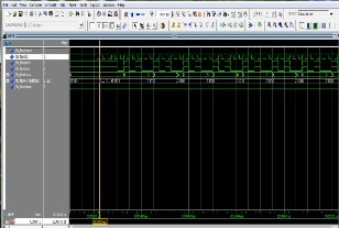
Fig 4. Output Generated For March BDN Algorithm
4. REFRENCES
[1] Slimane Boutobza, Michael Nicolaidis, Kheiredine M. Lamara, Andrea Costa ”Programmable Memory Bist” IEEEInternational Test Conference,2005.
[2] Zhiquan Zhang, Zhiping Wen, Lei Chen ”Bist Approach For Testing
Embedded Memory Blocks In System On Chip” IEEE,2009.
[3] V.G.Mikitjuk, V. N. Yarmolik, A.J.Van De Goor ”Ram Testing Algorithms For Detection Multiple Linked Faults” Delft Univ. Of technology,Netherlands.
Components | Comparison of Area overhead and delay |
Components | March BDN | March Y | March SS | March C- | March AB | March RAW | March LR |
Number of Slices | 38 | 23 | 33 | 30 | 34 | 35 | 36 |
Number of LUT | 70 | 42 | 63 | 57 | 63 | 66 | 67 |
Number of IOBs | 11 | 11 | 11 | 11 | 11 | 11 | 11 |
Total Gate count | 541 | 359 | 499 | 482 | 530 | 525 | 530 |
Delay(ns) | 6.214 | 5.081 | 5.447 | 6.270 | 6.212 | 5.669 | 6.286 |
IJSER © 2011
http://www.ijser.org
International Journal of Scientific & Engineering Research, Volume 2, Issue 12, December-2011 4
ISSN 2229-5518
[4] A. J. Van de goor, G. N. Gaydadjiev, V.N.Yarmolik, V.G.Mikitjuk
”IEEE 14th Vlsi Test Symposium,1996.
[5] G.harutunyan, V.A.Vardanian, Y.Zorian ”Minimal March Test Algorithm For Detection Of Linked Static Faults In Random Access Memories” IEEE 24th Vlsi Test Symposium,2006.
[6] Rob Dekker, Frans Beenker, Loek Thijssen ”Fault Modelling And Test Algorithm Development For Static Random Access Memories” IEEE International Test Conference,1988.
[7] Alberto Bosio, Giorgio Di Natale ”March Test Bdn:-A New March Test
For Dynamic Faults” Control Engineering And Applied Informatics,2008.
IJSER © 2011
http://www.ijser.org