
To achieve an effective single band operation for WLAN application from proposed antenna design. The design process of a proposed antenna is shown in Figure 1.
Antenna 1 Antenna 2 Antenna 3
Fig. 1. Various design process of proposed Antenna
International Journal of Scientific & Engineering Research, Volume 4, Issue 7, July-2013 2190
ISSN 2229-5518
S.Mathiyalagan, G.Jabert, M.Udhayakumar, C.Rajaraja Chozhan
Abstract- A single band compact micro-strip fed monopole antenna for W ireless Local Area Network (W LAN) application is presented. The proposed antenna design consists of a Y-Shaped monopole antenna with the ring slot and a designed rectangular slot which surrounds the monopole antenna. The experimental result shows that the proposed single band antenna has a return loss of -22.147 dB and band width is 1.2 GHz which lies at a frequency range of about 5.0 GHz to 6.2 GHz tuned at a centre frequency of 5.8 GHz, which can cover the WLAN-5.8 GHz frequency band. Then, the related radiation patterns have been observed at 5.8 GHz. The gain and efficiency of a proposed antenna is 4.43167 dBi and 80.698%.
Index Terms- W LAN, Rectangular slot, Ring slot, Micro-strip fed, Single band, Monopole antenna.
—————————— ——————————
In this letter, a relatively efficient single band
monopole antenna is presented for WLAN application.
Measurement shows that the antenna can effectively cover the bandwidth of 0.6 GHz (5.5 GHz-6.1 GHz), which satisfy the requirement both 5.8GHz WLAN bands. The antenna provides a impedance bandwidth of 0.6 GHz with corresponding frequency band 5.50–6.10 GHz, centered at
5.80 GHz, respectively. Although above antenna has many advantages, and there are some performances can be improved. The designs of antenna may increase cost or complexity for practical terminal design in [2][3]; or the overall dimensions of antenna are with large size in [7] and
————————————————
• Mathiyalagan.S is currently pursuing master degree in Communication
Systems in Bannari Amman Institute of Technology, India, PH-
919600354493. E-mail: mathiyalagans.co12@bitsathy.ac.in
• Jabert.G is currently pursuing master degree in Communication Systems in
Bannari Amman Institute of Technology, India. E-mail:
• Udhayakumar.M is currently pursuing master degree in Communication
Systems in Bannari Amman Institute of Technology, India. E-mail:
udhayakumarm.co12@bitsathy.ac.in
• Rajaraja Chozhan.C is currently working as an Assistant Professor in the
Department of Electronics and Communication Engineering in Bannari
Amman Institute of Technology, India. E-mail: c.chozhan@gmail.com
[10] compared to proposed antenna, which possibly limit the integration level of the future wireless communication system.
The designs of antenna may increase cost or complexity for practical terminal design in [2][3]; or the overall dimensions of antenna are with large size in [7] and [10] compared to proposed antenna, which possibly limit the integration level of the future wireless communication system. The effect of the antenna’s key structural parameters on its performance was also analyzed. In section 2, the various design process and optimal structure of the proposed antenna are presented. In section 3, simulation results are presented, where the efficient single band operation performances of the antenna are given and discussed. In section 4, the brief conclusions for the proposed system are given.
To achieve an effective single band operation for WLAN application from proposed antenna design. The design process of a proposed antenna is shown in Figure 1.
Antenna 1 Antenna 2 Antenna 3
Fig. 1. Various design process of proposed Antenna
IJSER © 2013 http://www.ijser.org
International Journal of Scientific & Engineering Research, Volume 4, Issue 7, July-2013 2191
ISSN 2229-5518
The antenna is simulated by using the FR4 substrate with the dielectric constant of 4.6, TanD of 0.025 and the thickness of the substrate is 1.6 mm. The copper
conductor is placed on the FR4 substrate, which has the thickness of 0.3 mm. Then, the feeding line is given to the bottom side of an antenna which has the characteristics impedance of 50 ohm. In this proposed antenna contains three shapes, first one is monopole antenna which is in the shape of Y-shaped slot surrounds by the rectangular slot. Second antenna is a small n-shaped cut, and it placed at top of the Y-shaped slot, and the split ring slot placed on the Y- shaped part of the first antenna. Then, the Y-shaped structure extruded by using the split ring slot. Antenna three (proposed antenna) contains all the rectangular slot, n-shaped cut and extruded Y-shaped slot by using the split ring slot. Thus, the third antenna achieves the efficient single band operation at 5.8 GHz for a WLAN application. Then the design configuration for an Antenna 3 (Proposed antenna) is presented in Figure 2.
follows:
The dimensions of a proposed antenna are as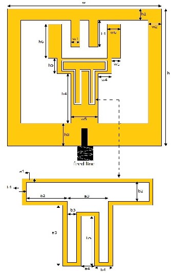
Fig. 2. Geometry of proposed antenna
Table. 1. Optimal dimensions of the designed antenna.
By suitable tuning the geometry parameters of this proposed antenna independently, an efficient single band antenna suitable for WLAN operation at the frequency range of 5.8 GHz is achieved. The antenna performance was simulated using ADS (Advanced Designing System) is prior to its fabrication. The simulated results presented show good agreement.
Based on the structure of the proposed model, an antenna prototype is simulated. The simulated return loss against the suitable frequency, with the proposed antenna can be resulted. In this proposed antenna, that the split- ring slot could improve the performance at the frequency range of 5.8 GHz band.
After simulation, the resulted return loss is shown
in Fig. 3, here the impedance bandwidths for -22.147 dB
return loss of the individual operating band is about 900
MHz (5.3 GHz to 6.2 GHz), which covering the centre
frequency at 5.8 GHz for WLAN operation band.
IJSER © 2013 http://www.ijser.org
International Journal of Scientific & Engineering Research, Volume 4, Issue 7, July-2013 2192
ISSN 2229-5518

antenna produced surface current at the WLAN operating frequency band of 5.8 GHz.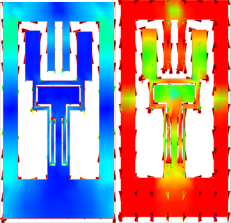
Fig. 3. Simulated return loss for proposed antenna
The different return losses at corresponding frequencies are given as follows:
Frequency (GHz) | Return Loss (dB) |
5.0 | -10.695 |
5.2 | -13.282 |
5.4 | -15.553 |
5.6 | -19.145 |
5.8 | -22.147 |
5.9 | -19.947 |
6.0 | -15.295 |
6.2 | -10.991 |
Table. 2. Return loss analysis
The power excitation mechanism of the proposed antenna scenario is shown in Fig. 4, the simulated proposed
(a) Before radiation (b) After radiation
Fig. 4. Surface current distribution and radiations of a proposed antenna.
In Fig. 4(a) and 4(b), blue color represents the no radiation at the starting point of the power distribution, green and red color indicates the minimum and maximum radiation during the effective power distribution. The current distributes mainly along the designed rectangular slot at 5.8 GHz. And the modified rectangular slot acts as a resonator for the lower resonance generation.
At 5.8 GHz, the far field radiation pattern of the simulated antenna is shown in Fig. 5, here the field radiated at all the four sides of the plot and which produces the efficient far field antenna parameters.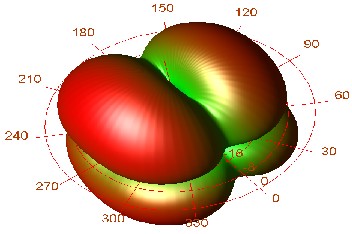
Fig. 5. Overall far field radiation pattern.
IJSER © 2013 http://www.ijser.org
International Journal of Scientific & Engineering Research, Volume 4, Issue 7, July-2013 2193
ISSN 2229-5518
The Fig. 6 shows the far field cut of the simulated radiation pattern. The resulted antenna parameters are, the radiated power is 0.219405 watts at the effective angle
3.65518 steradians which produces the gain of 4.43167 dBi and the directivity is 5.36302 dBi. The efficiency of the proposed antenna is 80.698%.
(b) Absolute fields
(a) Power
(c) Circular and linear polarization
Fig. 6. Far field cut of the simulated radiation pattern.
.
IJSER © 2013 http://www.ijser.org
International Journal of Scientific & Engineering Research, Volume 4, Issue 7, July-2013 2194
ISSN 2229-5518
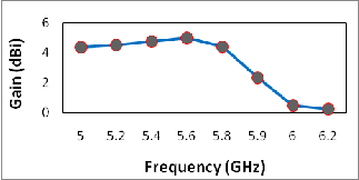
Fig. 7. Gain vs Frequency plot.
These far field radiation characteristics and antenna parameters are revealed that the proposed antenna is suitable and competent for the Wireless Local Area Network (WLAN) application.
A new micro-strip fed efficient single band monopole antenna has been proposed. By employing and exercising various types of resonant antenna structures in the scenario and later extruding a split ring slot in the y- shaped structure of the monopole antenna the design has been proposed. The proposed antenna can obtain the efficient single band operation in between the frequency range of 5.0 GHz to 6.2 GHz, which can cover the centre frequency at 5.8 GHz band for WLAN application. The layout of the proposed antenna is designed, and then simulated. The observed results show reasonable agreement, due to the better radiation pattern performance and achieves the effective gain in the required band, the proposed antenna is suitable and competent for WLAN application.
[1] “A Compact Printed Antenna for WLAN/WiMAX Applications” Huiqing Zhai, Member IEEE, Zhihui Ma, Yu Han, and Changhong Liang, Senior Member, IEEE Copyright (c) 2013 IEEE.
[2] “Compact CPW-Fed Tri-Band Printed Antenna with
Meandering Split Ring Slot for WLAN and WiMAX Applications” Pingan Liu, Yanlin Zou, Baorong Xie, Xianglong Liu, and Baohua Sun, IEEE Antennas and Wireless Prop.Lett, Vol.11, 2012.
[3] W.C.Liu, C.M.Wu, and N.C.Chu, “A compact CPW-fed
slotted patch antenna for dual band operation,” IEEE Antennas Wireless Propag.Lett., vol.9, pp.595–598, 2010.
[4] W.Hu, Y.Z.Yin, X.Yang, K.Song, Z.Y.Liu and L. H.Wen, “A wide open U-slot antenna with a pair of symmetrical L-strips for WLAN applications,” Prog. Electromagn. Res. Lett., vol.16, pp.141–149, 2010.
[5] T.N.Chang and J.H.Jiang, “Meandered T-shaped monopole antenna,” IEEE Trans. Antennas Propag., vol.57, no.12, pp.3976–3978, Dec.2009.
[6] W.C.Liu and C.F.Hsu, “Dual band CPW fed Y-shaped monopole antenna for PCS/WLAN application,” Electron.Lett., vol.41, pp.390–391, 2005.
[7] J.S.Chen, “Studies of CPW fed equilateral triangular
ring slot antennas and triangular ring slot coupled
patch antennas,” IEEE Trans Antennas Propag., vol.53, no.7, pp.2208–2211, Jul.2005.
[8] R.Karimian, M.Soleimani, and S.M.Hashemi, “Tri Band Four Elements MIMO Antenna System for WLAN and WiMAX Application,” Electromagnetic Wave and Application, Vol.26, Nos.17-18, 2348-2357, 2012.
[9] W.Hu, Y.Z.Yin, X.Yang and X.S. Ren, “Compact
printed antenna with shaped stub for dual band operation,” Electron. Lett., vol.46, pp.1644–1645, 2010.
[10] J.Jung, W.Choi, and J.Choi, “A small wideband
microstrip fed monopole antenna,” IEEE Microwave, Wireless Compon.Lett., vol.15, no.10, pp.703–705, Oct.2005.
IJSER © 2013 http://www.ijser.org