International Journal of Scientific & Engineering Research, Volume 4, Issue 4, April-2013 496
ISSN 2229-5518
CORRECTING COLOR CHANGES IN UNDERWATER IMAGES USING NAPC ALGORITHM
K.PRABHAKARAN M.E COMMUNICATION SYSTEM
. Abstract - In this paper, I propose a No black pixel constraints algorithm. This algorithm to remove the haze and light scattering from underwater images. Light scattering is caused by light incident of object reflected and deflected multiple times by particles present in water before reaching the camera. This the reason for turn lower visibility and color deviation of the image captured by camera. Color change caused by light travelling in the water for different wavelength. This paper propose a novel systematic approach to enhance the underwater images by NBPC algorithm.NBPC algorithm to calculate PSNR and MSE.NBPC algorithm output more efficient compare to (WCID)Wavelength compensation and image dehazing approach.
Index Terms-color change, light scattering, NBPC, underwater images, dehazing
1. INTRODUCTION
Underwater photography is a more important for ocean engineering [1].It is used to scientific research such as census of population, assessing geological environments, monitoring the sea life. Capturing image in underwater is challenging due to haze caused by light that is reflected from surface and is deflected and scattered by water particles. Color change due to light attenuated for different wavelength [2]-[3].
Haze is caused by suspended particles such as sand, minerals, plankton. Light reflected from object propagate into camera, light meets these suspended particles.

Fig. 1 Natural light enters from air to underwater scene point x. reflected light propagation distance d(x) to camera.
Scatters the light illustrated in Fig.1. Underwater image enhancement only focuses the object and image in NBPC. Techniques for remove the light scattering and color change effect. To compensate for visibility degradation [4], using image dehazing to restore the clarity of the underwater images [5].In both RGB and HSI color space to balance luminance distribution of color[6],dynamically mixing the illumination of object in distance-dependent way by using a multicolour light source to compensate color loss[6].
PRIVISIOUS WORK
The algorithm for wavelength compensation and image dehazing (WCID) existing work combines techniques of WCID to remove distortions caused by light scattering and color change. Dark-channel prior [7], an existing scene-depth derivation method, is used first to estimate the distances of the scene objects to the camera. The low intensities in the dark
channel are mainly due to three factors:
IJSER © 2013 http://www.ijser.org
International Journal of Scientific & Engineering Research, Volume 4, Issue 4, April-2013 497
ISSN 2229-5518
1) shadows, e.g., the shadows of creatures, plankton, plants, or rocks in seabed images; 2) colorful objects or surfaces, e.g., green plants, red or yellow sands, and colorful rocks/minerals, deficient in certain color channels; and 3) dark objects or surfaces, e.g., dark creatures and stone [8]. Based on the depth map derived, the foreground and background areas within the image are segmented. The light intensities of foreground and background are then compared to determine whether an artificial light source is employed during the image acquiring process. If an artificial light source is detected, the luminance introduced by the auxiliary lighting is removed from the foreground area to avoid overcompensation in the stages followed. Next, the dehazing algorithm and wavelength compensation are utilized to remove the haze effect and color change along the underwater propagation path to the camera. The residual energy ratio among different color channels in the background light is employed to estimate the water depth within an underwater scene. Energy compensation for each color channel is carried out subsequently to adjust the bluish tone to a natural color.With WCID, expensive optical instruments or stereo image pairs are no longer required. WCID can effectively enhance visibility and restore the color balance of underwater images, rendering high visual clarity and color fidelity.
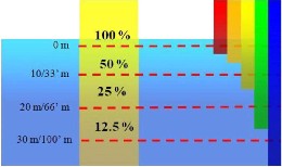
Fig.2 light travel in the water at different wavelength
PROPOSED WORK
Image enhancement in No black pixel constraints.NBPC (No black pixel constraints) algorithm used to improve the image quality for underwater images. It is able to detect the presence of fog and to estimate the visibility distance which is directly related to the k in Koschmieder’s law. This algorithm, also known as the inflection point algorithm.
KOSCHMIEDER’S LAW
Law relating the apparent contrast Cd of an object against a sky background, at a given distance of observation d,to the inherent contrast C0 and to the atmospheric transmissivity T, which is assumed to be uniform Cd = C0 .Td/d
FOG MODELING
Fog is an accumulation of water droplets or ice crystal fines accompanied by hygroscopic, water-saturated fine particles that act to reduce visibility. Its composition is thus identical to that of a cloud whose base would actually touch the ground. Whenever horizontal visibility has been diminished to less than one kilometre, the term fog gets employed. Should the level of visibility reach or surpass this threshold, the appropriate.
In proposed work to improve the image quality and to improve the PSNR and MSE by using NBPC. NBPC to detect the fog and remove the fog affect this process more efficient compare to WCID. All image capture in light source manner for underwater images. This image affected in the light sattering and color change distortion. This two distortion overcome by existing work WCID, but we proposed work done in solve this two distortion output more efficient compare to
IJSER © 2013 http://www.ijser.org
International Journal of Scientific & Engineering Research, Volume 4, Issue 4, April-2013 498
ISSN 2229-5518
WCID. Image quality also improved. Performance improved.
Underwater model
The background light in an underwater image can be used to approximate the true in- scattering term in the full radiative transport equation to achieve the following simplified hazy image formation model.
Iλ(x) = Jλ(x) + (1-tλ(x).Bλ , λϵ{red,green,blue} (1)
Where x is a point in the underwater scene, Iλ(x) is the image captured by the camera, Jλ(x) is the scene radiance at point, x,tλ(x) is the residual energy ratio of Jλ (x) after reflecting from point x in the underwater scene and reaching the camera, Bλ is the homogeneous background light, and λ is the light wavelength. Note that the residual energy ratio tλ(x) is a function of both wavelength λ and the object–camera distance d(x).t λ(x) summarizes the overall effects for both light scattering and color change suffered by light with wavelength λ traveling the underwater distance d(x).The direct attenuation term Jλ (x) tλ(x) describes the decay of scene radiance in the water. The residual energy ratio tλ(x) can be represented alternatively as the energy of a light beam with wavelength λ before and after
traveling distance d(x) within the water Eλ
wavelength transmitted, as illustrated in Fig. 2, where red light possesses longer wavelength and lower frequency and thereby attenuates faster than the blue counterpart. This results in the bluish tone prevalent in underwater images.For every meter of ocean type I that a light beam passes through, the values of normalized residual energy ratio Nrer (λ) in red (700 m) light, green (520 m) light, and blue (440 m) light are 82%, 95%, and 97.5%, respectively. Based on the water type considered, the normalized residual energy.
underwater image formation model
The proposed NBPC algorithm proceeds in a direction inverse to the underwater image formation path discussed above, as depicted in Fig.4. First, consider the possible presence and influence of the artificial light source. Next, remove the light scattering and color change that occurred along the course of propagation d(x) from the object to the camera. Finally, compensate the disparities of wavelength attenuation for traversing the water depth D to the top of the image and fine-tune the energy loss by deriving a more precise depth value for every point within an image. Fig 1 illustrates an underwater image formation model. Homogeneous skylight entering above into the water is the major source of illumination in an underwater environment. Incident light
(x) and, Eλ
(x) respectively, as follows
traverses from the surface of water reaching
residual
λ
(x)
the image scene, covering a underwater scene
point with depth range from depth D through

tλ(x) = =10-β(λ)D(X )=Nrer(λ)d(X)
E intial(x) (2)
λ
Where the normalized residual energy ratio Nrer (λ) corresponds to the ratio of residual to initial energy for every unit of distance propagated and β(λ) is the medium extinction coefficient.The normalized residual
energy ratio Nrer (λ) depends on the light
D+R, where R corresponds to the image depth range. During the course of propagation, light with different wavelengths is subjected to varying degrees of attenuation.The color change of ambient lighting makes the underwater environment tinted with a bluish hue. As airlight incident from air to the water reaches the underwater scene point x with
D(X) i.e..D<(X ) D+R, amount of residual
IJSER © 2013 http://www.ijser.org
International Journal of Scientific & Engineering Research, Volume 4, Issue 4, April-2013 499
ISSN 2229-5518
light W(X) formed after wavelength attenuation can be formulated according to the
energy attenuation model in (2) as follows:
d(x), is known through the dark-channel prior, the value of residual energy ratio Nrer (λ)d(x) after wavelength attenuation can be calculated.
w A D(x)
Eλ (x) =Eλ
(x).Nrer(λ)
,λϵ{red ,green
Thus, the direct attenuation term
A d(x)
,blue). (3)
Eλ (X).Nrer (λ)
.ρλ(x) is derivable through a
At point x, the light reflected again travels distance d(x) to the camera forming pixel Iλ (X), λ € {red, green, blue}. Along this underwater object–camera path, two phenomena occur, i.e., light scattering and color change. Note that color change occurs not only along the surface–object propagation path but also along the object–camera route. Light Jλ(x) emanated from point x is equal to the amount of illuminating ambient light
Eλw(x) reflected,
dehazing procedure.The surface–object distance D(X) is calculated by comparing the residual energy ratio of different color channels. Given the water depth D(X), the amount of reflecting light Eλ (X).ρλ(X), i.e., free of light scattering and color change, from point x illuminated by airlight is determined. Moreover,the artificial light source L is often provided to overcome insufficient lighting commonly encountered in an underwater photographic environment.The luminance
contributed by the artificial light source has to
Eλw (x).ρλ(x) = EA
.Nrer
λ(X)
(λ)D(x).ρλ(x),where ρλ(x) is the reflectivity of
point x for light with wavelength λ. By following the image formation model in a hazy environment in (1), the image Iλ (x) formed at the camera can be formulated as
be removed before the dehazing and wavelength compensation operations to avoid overcompensation. When the artificial light source L is detected, the light emitted Eλ has first to travel distance d(x) before reaching
point x .The residual energy after the course of
follows:
Iλ (x) = (EλA(x).Nrer(λ)D(x) .ρλ(x)). t λ (x)+(1-tλ
propagation is Eλ
. Nrer (λ)
d(x)
.The total
(x)). Bλ , λ ϵ {red,green,blue} (4)
The background light Bλ increases as the object is placed farther away from the camera. Alternatively, the residual energy ratio tλ(x) in the above equation can be represented in terms of normalized residual energy ratio Nrer (λ) using (2) as follows:
Iλ (x) = (EλA(x).Nrer(λ)D(x) . ρλ(X)).
Nrer(λ)d(x)+(1-Nrer(λ)d(x)) . Bλ , λ ϵ
{red,green,blue} (5)
Equation (5) incorporates light scattering during the course of propagation from object to the camera d(x), and the wavelength attenuation along both the surface–object path D(x) and object–camera route d(x), Once the
scene depth, i.e., object– camera distance
amount of light impinges on point x is
therefore the summation of ambient lighting Eλw (x) and the attenuated artificial light E L . Nrer(λ)d(x) .
The total amount of incident light E A
λ
(x). Nrer (λ) D(x) + E L . Nrer (λ) d(x) is reflected with reflectivity ρλ(x) and bounces back distance d(x) before reaching the camera.
During both forward and backward courses of propagation pertinent to d(x), color change occurs. Accordingly, (5) can be further modified as the hazy image formation equation.
IJSER © 2013 http://www.ijser.org
International Journal of Scientific & Engineering Research, Volume 4, Issue 4, April-2013 500
ISSN 2229-5518
A D(x)
Iλ (x) =((Eλ
L
(x).Nrer(λ) +
d(x)
d(x)
(Eλ (x).Nrer(λ)
Nrer(λ)d(x)) . Bλ ,
). ρλ(x)).Nrer(λ)
)+(1-
Underwater image corrected image
λ ϵ{red,green,blue} (6)
IMAGE DEPTH RANGE:
The image acquired covers a depth range of tan underwater scene from D to D+R, as shown in Fig.1. When light penetrates through water covering the depth range, a disparate amount of color change will be induced at the top and at the bottom of the image. This phenomenon necessitates varying energy compensation adjusted according to the depth of each underwater point to correctly rectify color change. Let the top background pixel be the point at the top of the image background with the underwater depth D,and let the bottom point at the bottom of the image background with the underwater depth D+R,where R represents the range of water depth covered in an image.
Derivation of d(x) by dark-channel prior & image matting

depth map
Segmentation of foreground and background
Artificial NO
light source L
NBPC color change along the course of propagation D through D+R
Estimation of scene range from depth D through D+R
NBPC light scattering & color change along the path d(x)
Removal of artificial light
source L
Fig.3 Flow chart of NBPC algorithm
RESULT
Performance evaluation

IJSER © 2013 http://www.ijser.org
Image obtained after applying NBPC
International Journal of Scientific & Engineering Research, Volume 4, Issue 4, April-2013 501
ISSN 2229-5518
CONCLUSION
NBPC algorithm proposed in this paper can effectively restore the color balance and remove haze. This method efficient compared to WCID method.NBPC performance evaluation is to improve the PSNR and MSE.
In future work to enhance images for no- black-pixel constraint NBPC and pa algorithm.
REFERENCES
[1] Carlevaris-Bianco.N, Mohan .A, and Eustice R.M, “Initial results in underwater single image dehazing,” in Proc. IEEE OCEANS, 2010, pp. 1–8.
[2] Chao .L and Wang .M, “Removal of water scattering,” in Proc. Int. Conf. Comput. Eng. Technol., 2010, vol.
2, pp. 35–39.
[3] Fattal .R, “Single image dehazing,”
in Proc. Int. Conf. Comput. Graph
Interact. Tech., 2008, pp. 1–9.
[4] He .K, Sun .J, and Tang .X, “Single image haze removal using Dark Chan nel Prior,” in Proc. IEEE CVPR, 2009, vol. 1, pp. 1956–1963.
[5] Hou .W, Gray D.J, Weidemann A.D, Fournier G.R, and Forand J.L, “Automated underwater image restoration and retrieval of related optical properties,” in Proc.IGARSS, 2007, vol.
1, pp. 1889–1892.
[6] Houghton J.T, the Physics of Atmospheres, 2nd ed. Cambridge,Cambridge Univ. Press, 2001, ch. 2.
[7] Iqbal .K, Abdul Salam .R, Osman
.A, and Zawawi Talib .A, “Underwater image enhancement using an integrated color model,” Int. J. Comput. Sci., vol.34, no.2,pp. 2– 12, 2007
[8] Levin .A, Lischinski .D, and Weiss Y, “A closed form solution to natural image matting,” in Proc. IEEE CVPR, 2006, vol. 1, pp. 61–
68
IJSER © 2013 http://www.ijser.org
International Joumal of Scientific & Engineering Research, Volume 4, Issue 4, April-2013
ISSN 2229-5518
502
IJSER ©2013
http://www.iiSer_org
International Joumal of Scientific & Engineering Research, Volume 4, Issue 4, April-2013
ISSN 2229-5518
503
IJSER ©2013
http://www.iiSer_org