International Journal of Scientific & Engineering Research, Volume 3, Issue 9, September-2012 1
ISSN 2229-5518
COMPARATIVE EXPERIMENTAL INVESTIGATION FOR REDUCING HIGH SPEED STEEL TOOL WEAR RATE BY CRYOGENIC PROCESS
Archit Shrivastava
Abstract—The main objective of this research is to find the optimum working condition to reduce tool wear rate in HSS drill bit. Cryogenic treatment on HSS drill bit has shown changes in its properties like increased hardness; increase in wear resistance which res ults in increase in tool life. During drilling operation tool wear depends on many factors but we have concentrated on 3 major factors which we can change i.e. drilling speed, feed rate and tool condition. We have compared untreated HSS drill bit with Cryogenic Treated HSS drill bit using taguchi’s analysis. Taguchi analysis gives us the optimum working condition for HSS dri ll bit which shows that cryogenic Treated tool is better than non treated tool.
Index Terms— Cast Iron , Cryogenic Process, Drilling, Hardness ,High Speed Steel Drill bit, Taguchi analysis, Optimum Working
Condition, Tool Wear Rate.
1 INTRODUCTION
—————————— ——————————
eep cryogenic Treatment system is the methodology of
―ultra low temperature‖ processing of material to en- hance their metallurgical properties. The materials are
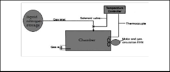
treated in the cryogenic chamber as shown in Fig. 1.
The twist drill bit is the type used in almost all the drilling operations today. It comprises a cutting point at the tip of a cylindrical shaft with helical flutes. In present work, we used the twist drill bit of following specifications
Diameter: 8 mm, Flute length: 75 mm, Overall length: 117 mm,
Tip angle: 118o Helix angle: 20o
The twist drill bit used is shown in Fig. 3.
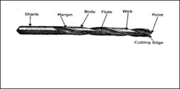
Fig. 1. Cryogenic Chamber
The process involves reducing and raising the temperature. Thermal control is achieved by continuously monitoring in- puts and regulating the flow of liquid nitrogen into the cham-
Fig. 3. Twist Drill Bit
Diameter: 8 mm, Flute length: 75 mm, Overall length: 117 mm, Tip
ber and alternating the heat. Precise program control takes the cycle through three phases of descend, soak, and ascend with
angle: 118o
Helix angle: 20o
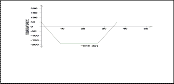
no fear of thermal shock. The complete temperature variation with respect to time is shown in Fig. 2.
Fig. 2. Cooling Curve
It is imperative that a slow descend is followed by a soak period of around 24 hours at -196OC and then raised to room temperature with a slow ascend.
————————————————
 Archit Shrivastava is currently pursuing masters degree program in industrial engineering and Management in SGSITS, INDIA, PH-9691525499. E-mail: Shrivastava_archit@yahoo.com
High speed steel (HSS) is a form of tool steel. HSS bits are
much more resistant to heat. They can be used to drill metal,
hardwood, and most other materials at greater cutting speeds
than carbon steel bits.HSS tools are so named because they
were developed to cut at higher speeds. Developed around
1900 HSS is the most highly alloyed tool steels. The tungsten
(T series) was developed first and typically contains 12 - 18%
tungsten, plus about 4% chromium and 1 - 5% vanadium. Most grades contain about 0.5% molybdenum and most grades contain 4- 12% cobalt.
Cryogenic treatment on HSS will result in the conversion of retained austenite into martensite. This results in increase in hardness of HSS drill bit due to increase in density of disloca- tion and gaps.
Calculation of optimum working condition for HSS drilling bit for drilling cast iron has not been reported yet.
IJSER © 2012
http://www.ijser.org
The research paper published by IJSER journal is about COMPARATIVE EXPERIMENTAL INVESTIGATION FOR REDUCING HIGH SPEED STEEL TOOL WEAR RATE BY CRYOGENIC PROCESS 2
ISSN 2229-5518
2 EXPERIMENTAL STUDY
Our experimental aim is to compare the treated tool and un- treated tool; we have calculated the thrust force, torque using drill tool dynamometer at different drilling speed, feed rate and tool condition (treated tool and untreated tool).
And surface roughness is the most important parameter which we always desire to reduce to minimum. Hence, we have cal- culated the surface roughness of drilled holes using talysurf. And we have calculated the hardness of treated HSS drill bit using Rockwell hardness machine.
2.1 Hardness Test
Hardness test of cryogenic treated HSS drill bit was done us- ing Rockwell hardness machine which works on C scale and values are in HRC and load of 150 Kgf is used to calculate hardness and 120o diamond cone is used to penetrate the HSS drill bit. The calculated values are given in Table 2.
TABLE 1
ROCKW ELL HARDNESS TEST

Top, middle and bottom represents the area of the shank of tool. Hardness Va l- ues are in HRC
We can say that cryogenic treated HSS drill bit has very high
Hardness compared with non treated drill bit.
2.2 Drilling Test
During drilling operation tool wear depends on many factors but we have concentrated on 3 major factors which we can change i.e. drilling speed, feed rate and tool condition. Drilling was performed to calculate thrust force and torque on HSS drill bit using drill tool dynamometer. Hence, we will find the optimum condition for minimum thrust force and torque to reduce tool wear. We have repeated drilling process three times for each experimental set up. Taguchi’s method is used to find the optimum condition for drilling cast iron using HSS drill bit. We have selected four different speeds: A: 500, 700,
900, and 1100 (rpm). And two different feed rate: B: 0.05, 0.08 (mm/rev). And two different tool conditions: Cryogenic Treated Tool (CT) and Non Treated Tool (NT).
We have assigned four coded values for different speed, feed rate, and tool condition shown in Table 1.
TABLE 2
CODED VALUES
2.3 Taguchi’s Analysis
Taguchi’s L16 rule fits for our experimental conditions. Taguchi’s L16 layout is given in table 2.
TABLE 3
TAGUCHI’S L16 LAYOUT

The values of speed, feed rate and tool condition in Taguchi’s
L16 layout is shown in table 3.
TABLE 4
EXPERIMENTAL VALUES IN PLACE OF CODED VALUES
IJSER © 2012
http://www.ijser.org
The research paper published by IJSER journal is about COMPARATIVE EXPERIMENTAL INVESTIGATION FOR REDUCING HIGH SPEED STEEL TOOL WEAR RATE BY CRYOGENIC PROCESS 3
ISSN 2229-5518
We have calculated thrust force and torque three times for each experimental condition using drill tool dynamometer. Surface roughness of every drilled hole is also calculated. The experimental reading for torque (TO), thrust force (TH) and surface roughness (R) is shown in table 4.
TABLE 5
EXPERIMENTAL READINGS FOR TORQUE (TO) AND THRUST FORCE
(TH) AND SURFACE ROUGHNESS (R)
TO represent readings of torque during drilling and suffix 1, 2 and 3 refers to repetation of same process for high accuracy.
TH represents readings of thrust force. R represents readings of surface rough-
ness.
Model calculation of SN ratio for thrust force:  = 8321.333
St1 = (52) 2 + (54) 2 + (52) 2 = 8324
Se1 = 8324 – 8321.333 = 2.666667
 = 1.333333
  = 33.17994
SN1 is the SN ratio for thrust force for cryogenic treated tool at
drilling speed 500 rpm, feed rate 0.05mm/rev.
Similarly SN2, SN3, SN4 … SN16 has been computed for
thrust force.
After calculating SN ratio for each experiment, the average SN
value is calculated for each drilling speed, feed rate and tool
condition.
Where, SNA1 =  = 33.299
SNA1 is the average of SN ratio for drilling speed of 500 rpm. Similarly, SNA2, SNA3, SNA4 are calculated for drilling speed of
700, 900, 1100 respectively.
Similarly, SNB1 SNB2, SNB3, SNB4 are calculated for feed rate of
0.05, 0.08, 0.05, 0.08 respectively. SNC1 SNC2, SNC3, SNC4 are calculated for tool condition of CT, CT, NT, NT respectively.
Main effect graph is plotted for mean of SN ratio is shown in
Fig. 4.

Based on the readings obtained, we will calculate the SN ratio for thrust force, torque, surface roughness.
List of formulas for calculating SN ratio:

 Sum of squares due to mean
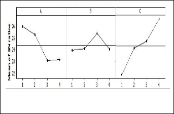
Fig. 4. Main effects plot for SN ratio for thrust force
A represents drilling speed, B represents fed rate, and C represents tool condition
St: Total Sum of Squares = (T1 ) 2 + (T2 ) 2 + (T3 ) 2
Se: Error Sum of squares = St – Sm


Ve: Error Variance (mean square) SN: Signal to noise ratio
We need to minimize the value of thrust force. Fig. 4, shows the Variation in SN ratio for thrust force.
Hence, the optimal condition is (A2, B4, and C2) for minimum thrust force.
IJSER © 2012
http://www.ijser.org
The research paper published by IJSER journal is about COMPARATIVE EXPERIMENTAL INVESTIGATION FOR REDUCING HIGH SPEED STEEL TOOL WEAR RATE BY CRYOGENIC PROCESS 4
ISSN 2229-5518
The same procedure is repeated for the calculation of means of SN ratio for Torque and surface roughness and the following Fig. 5. and Fig. 6. are ploted
Fig. 5. Main effects plot for SN ratio for Torque
A represents drilling speed, B represents feed rate, and C
represents tool condition
We need to minimize the value of torque. Fig. 5 shows the
Variation in SN ratio for Torque.
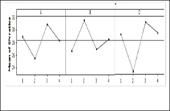
The optimal condition is (A3, B1, C1) for minimum torque.
Fig. 6. Main effects plot for SN ratio for Surface Roughness A represents drilling speed, B represents feed rate, and C represents tool condition
We need to minimize the value of surface roughness. Fig. 6, shows the Variation in SN ratio for surface roughness. Hence, the optimal condition is (A2, B1, and C2) for minimum surface roughness.
3 RESULT AND DISCUSSION
THRUST FORCE
The tool condition has the variation of 3.712995, speed has the
variation of 1.817923, and feed rate has the variation of 1.54837 in SN ratio for calculated thrust force.
We need to minimize the thrust force. The optimal condition is
(A2, B4, and C2) from Fig. 4.
So, it is better to drill with cryogenic treated tool at a speed of
700 rpm and feed rate of 0.08 mm/rev. The value of thrust force at this condition is 65.3333 Kgf minimum.
TORQUE
The tool condition has the variation of 4.798311, speed has the
variation of 2.931654, and feed rate has the variation of
1.419755 in SN ratio for calculated torque. We need to minim-
ize the Torque. The optimal condition is (A3, B1, and C1) from
Fig. 5.
So, it is better to drill with cryogenic treated tool at a speed of
900 rpm and feed rate of 0.05 mm/rev. The value of torque at
this condition is 0.12 Kg-m minimum.
SURFACE ROUGHNESS
The tool condition has the variation of 7.845503, speed has the variation of 5.456697, and feed rate has the variation of 4.82919 in SN ratio for calculated surface roughness.
We need to minimize the surface roughness. The optimal con-
dition is A2, B1, and C2 from Fig. 6.
So, it is better to drill with cryogenic treated tool at a speed of
700 rpm and feed rate of 0.05 mm/rev. The value of surface
roughness at this condition is 5.2266 µm minimum
Since, we need to minimize all the factors in one combination; we will optimize these values based on the amount of effect on the thrust force, torque & surface roughness.
The cryogenic treated tool has the largest effect on the thrust
force, torque and surface roughness. Feed has the smallest
effect on the thrust force, torque & surface roughness (Ra) and,
the effect is highest in surface roughness (7.845503) due to tool condition, and lowest in speed (3.712995)
Hence, the final optimum condition for (speed, feed rate, tool condition) is (700, 0.05, CT)
At this optimal condition the value of (thrust force, torque,
and surface roughness) is (57.66 Kgf, 0.1166 Kg-m, 5.1466 µm) This results in minimum value of factors which affects tool wear. The tool becomes more wear resistance and its life in- creases.
4 CONCLUSION
Drilling exercises were performed using cryogenically treated and non-treated HSS drills to study the tool performance. Based on the study the following conclusions were drawn:
The hardness of the High speed steel drill bit is increased by
cryogenic treatment.
Cryogenic treated tool resulted in lesser thrust force, torque
and yielded superior surface finish compared to that of non-
treated drill bits.
The tool condition had the largest effect on the thrust force,
torque and surface roughness. Feed had the smallest effect on the thrust force, torque and the surface roughness.
Based on the results it was concluded that cryogenic treatment can yield significant improvement in both productivity and product quality and hence overall machining economy offset- ting the cost of cryogenic cooling.
IJSER © 2012
http://www.ijser.org
The research paper published by IJSER journal is about COMPARATIVE EXPERIMENTAL INVESTIGATION FOR REDUCING HIGH SPEED STEEL TOOL WEAR RATE BY CRYOGENIC PROCESS 5
ISSN 2229-5518
REFERENCES
[1] Rupinder singh and Kamaljit singh, ―Enhancement of tool material machining characteristics with cryogenic treatment‖ Preceedings of the 2010 International conference on Industrial Engineering and op- erations management ,Dhaka, Bangladesh, January 9-10, 2010.
[2] Gill S. S. and Singh H. and Singh R. and Singh J., ―Cryoprocessing of
cutting tool materials‖ International Journal of Adv Manufacturing
Technology, 2009, DOI 10.1007/s00170-009-2263-9
[3] Gill S. S. and Singh H. and Singh R. and Singh J., ‖Wear Behaviour of cryogenically treated tungsten carbide inserts under dry and wet turning conditions‖ International journal of machine tools manufac- turing, Volume 49, pp. 256-260., 2008
[4] Lakwinder pal Singh and Jagtar Singh ―Effects of cryogenic treat- ment on high speed steel tooos‖ Journal of Engineering and technol- ogy, Volume 1, Issue 2, pp. 88-93, 2011 , DOI: 10.4103/0976-
8580.86640
[5] Rupinder Singh and Kamaljit Singh ―Enhancement of Tool Material Machining characteristics with Cryogenic Treatment‖ National Con- ference on Advancement and futuristic trends in mechanical and ma- terial engineering, February 19-20, 2010.
[6] Sahoo P. and Barman T. K. and Routara B. C., ―Taguchi based practical dimension modeling and optimization in CNC turning‖, Advance in Production Engineering and Management, Volume 3, Number 4, pp. 205-217, 2008.
[7] Shetty R. and Pai R. and Kamath V. and Rao S. S., ―Study on
Surface Roughness Minimization in Turning of DRACs using Surface Roughness Methodology and Taguchi under Pressured Steam Jet Approach‖, ARPN Journal of Engineering and Applied Sciences, Volume 3, Number 1, pp. 59-67, 2008
[8] Singh H. and Kumar P., ―Optimizing Feed Force for Turned Parts through the Taguchi Technique‖, Sadhana, Volume 31, Number 6, pp. 671–681, dec 2006.
[9] Yong A.Y.L. and Seah K.H.W. and Rahman M., ―Performance of
Cryogenically Treated Tungsten Carbide Tools in Milling Operation,‖ International Journal of Advanced Manufacturing Technology, Volume 32, Numbers 7-8, 2007, pp. 638-643, DOI:
10.1007/s00170-005-0379-0
IJSER © 2012
http://www.ijser.org