International Journal of Scientific & Engineering Research Volume 2, Issue 4, April-2011 1
ISSN 2229-5518
Bus Proximity Indicator
(An Intelligent Bus Stop)
Prof. A.P. Thakare, Mr. Vinod H. Yadav
A thought of project “Bus Proximity Indicator” is the best solution for the above situation and is best suitable for the B.E.S.T. (The Brihanmumbai Electric Supply & Transport) In this a wireless RF linkage between a certain bus and a bus stop can be
used for determination of the bus proximity that help’s commuter to know how far his bus is. This project tells him the Bus number, bus name and the approaching time by displaying it on the LCD which is on the bus stop. This project also satisfies the need of automization in bus services.
Index Terms— Amplitude Shift Keying, Atmel’s AT89C52 Microcontroller, RF encoder/ decoder IC ST12CODEC, C51 Cross
Compiler, Radio frequency transmitter, Timer astable multivibrator.
—————————— • ——————————
HE Bus Proximity Indicator presented in the section uses radio frequency of 433 MHZ. The prefixed code of the bus
is generated by the encoder ST 12 CODEC. This code is trans- mitted after Amplitude shift Keying. The receiver positioned at the bus stop detects the radio frequency signal and the bus identification is done by decoder ST 12 CODEC.
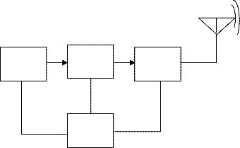
The block diagram and relevant description of the same is giv- en including of Transmitter and receiving section
TAMV
555
ENCODER
BATTERY
RF TX
The basic block diagram for the Transmitter section is as shown in the block diagram. It consists of the following blocks:
a) TAMV 555 b)Encoder
c) RF Transmitter
d)Battery
LEGEND:
TAMV – Timer astable multivibrator,
RF TX – Radio frequency transmitter
The 555 timer IC is used as an astable multivibrator and as an address setter for triggering an IC ST12CODEC which is used as an encoder
(Figure 1: Transmitter Section of Bus Proximity Indicator)
b) RF Encoder:
A logic circuit that produces coded binary outputs from encoded inputs. This uses ST CODEC 12BT for encoding the data. The encoder encodes the data and sends it to RF Transmitter. The IC ST12 CODEC is a single chip telemetry de- IJSER © 2011
http://ww w.ijser.org
International Journal of Scientific & Engineering Research Volume 2, Issue 4, April-2011 2
ISSN 2229-5518
vice, which may be an encoder or a decoder. When combined with a Radio transmitter / receiver it may be used to pro- vide encryption standard for data communication system The IC ST12CODEC performs all the necessary data manipu- lation and encryption for an optimum range reliable radio link.
Transmitter and receiver use same IC ST12 CODEC in RF encoder mode for serial communication. This IC is capable of transmitting 12 bits containing 4 bit address bit and 8 bit data. The transmitted information is sent by RF with 434 MHZ RF transmitter. ST12 CODEC works on 5v.
RF transmitter ’s uses ASK (Amplitude Shift Keying) for modulating the data send by ST12 CODEC .This modulated
information is then transmitted with 433 MHz frequency through RF antenna to receiver. It helps in transmitting data present in encoder via antenna at particular frequency.
A single 9V battery is used to supply power to the transmitter section.
The basic block diagram for the Receiver section is as shown above. It consists of the following blocks, a) RF Receiver
b)RF Decoder
c) Microcontroller d)Power supply
e) LCD
LEGEND:
RF RX: Radio frequency receiver
LCD: Liquid crystal display
RFDC: RF Decoder
µC: Microcontroller AT 89C51
(Figure 2: Receiver Section of Bus Proximity Indicator)
It is enhanced single chip IC RWS 434 which receives the 433.92 MHz transmitted signal, transmitted by RF transmit- ter. It uses ASK (Amplitude Shift Keying) conventional heterodyne receiver IC for remote wireless applications.
A logic circuit that used to decode coded binary word. This uses IC ST12 CODEC for decoding the data which is transmitted by IC RWS 434. The decoder converts the serial data which has been sent from RF receiver to parallel form and sends it to microcontroller. The coded data decoded by this block is given to LCD.
This is the most important block of the entire system. The microcontroller works at crystal frequency of 11.0592 MHz. It receives the parallel data from ST12 CODEC IC and compares it with the program code which already stored in it. This microcontroller has the baud rate 9600 bits/sec.
The 89C52 is a low power, high performance CMOS 8 bit microcomputer with 8k bytes of flash programmable and
erasable read only memory (PEROM).The device is manufactured using Atmel’s high density nonvolatile memory technology and it is compatible with the industry standard 89C51 and 89C52 instruction set and pin out.
The on chip Flash allows the program memory to be reprogrammed in system or by a conventional nonvolatile memo-
ry programmer. By combining a versatile 8-bit CPU with flash on a monolithic chip, the Atmel’s AT89C52 is a powerful microcomputer which provides a highly flexible and cost effective solution to many embedded control applications.
IJSER © 2011 http://ww w.ijs er.org
International Journal of Scientific & Engineering Research Volume 2, Issue 4, April-2011 3
ISSN 2229-5518
The performance of the master box depends on the proper functioning of the power supply unit. The power supply converts not only A.C into D.C, but also provides output voltage of 5V, 1 amp. The essential components of the power supply are Transformer, four diodes which forms bridge rectifier, capacitor which work as a filter and positive voltage regulator IC 7805. It provides 5v to each block of the transmitter.
LCD modules are useful for displaying the information from a system.
These modules are of two types, Text LCD and Graphical LCD. In this project a Text LCD of size (16 x 2) with a two line by sixteen character display is used to display the various sequence of operations during the operation of the project. This is used for visual information purpose. The LCD will display the data coming from normal keyboard or form microcontroller as a visual indication.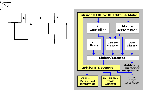
RF RX
RFDC µc
LCD
16X2
(Figure 3: Software tool of Bus Proximity Indicator)
KEIL
POWER SUPPLY
The Keil C51 Cross Compiler is an ANSI C Compiler that is written specifically to generate fast, compact code for the
8051 microcontroller family. The C51 Compi- ler generates object code that matches the efficiency and speed of assem- bly programming.
When we use Keil software tools, the project devel- opment cycle is roughly the same as it is for any other soft- ware development project.
1. Create a project, select the target chip from the device
database, and configure the toll settings.
2. Create source file in C or assembly.
3. Build your application with the project manager.
4. Correct errors in the source files.
5. Test the linked application.
A block diagram of the complete 8051 tool set may best illustrate the development cycle.
As demonstrated in this document, the numbering for sections upper case Arabic numerals, then upper case Arabic numerals, separated by periods. Initial paragraphs after the section title are not indented. Only the initial, introductory paragraph has a drop cap.
The paper “Bus Proximity Indicator” exhibits the arrival of a particular bus on the display provided at the bus stop. The intention of presenting the paper is to facilitate the commuters waiting at the city bus stops. The CODEC used in the paper generates eight bit coded information allowing the identification up to 256 bus routes and is compatible to the AT89C51. In addition, it works on a power supply ranging from 2 to 5 volts which makes it handy in the mobile
IJSER © 2011 http://ww w.ijser.org
International Journal of Scientific & Engineering Research Volume 2, Issue 4, April-2011 4
ISSN 2229-5518
bus. The transmitter and receiver used works on 434MHz at 2 – 12 volt and hence have dual advantage of power sav- ing as well as a range of around 500 feet. The 500 feet (150 Meter) is quite a high range for the detection of the city bus arrival
[1] 8051 Microcontroller Architecture Programming and Application by Kenneth J Ayala
[2] 8051 Microcontroller and Embedded systems by Mazidi and Mazidi
[3] Embedded Controller Forth for the 8051 Family
[4] 8051 Microcontroller, The: Hardware, Software and Interfacing & Applications
[5] WWW. Google.Com
[6] WWW.datasheetcatlog.com
[7] digikey.com/1/parts/638617
[8] http://www.sunrom.com
[9] http://www.sparkfun.com/products/8946
————————————————
Mr. Vinod H. Yadav is currently pursuing masters degree program in Digital Electronics engineering in Sant Gadgebaba Amravati University,
IJSER © 2011 http://ww w.ijs er.org