International Journal of Scientific & Engineering Research, Volume 4, Issue 12, December-2013
ISSN 2229-5518
Bilinear z-transformation and Pascal’s triangle
Phuoc Si Nguyen Melbourne, Australia nguyensiphuoc@outlook.com
Abstract— Bilinear z-transformation is the most common method for converting the transfer function H(s) of the analog filter to the transfer function H (z) of the digital filter and vice versa. In this work, introducing the relationship between the digital coefficients and the analog coefficients in the matrix equation definitely involves the Pascal’s triangle.
Index Terms—Bilinear z-transform, warping frequency, pre-warping frequency, frequency transformation, low pass to low pass, low pass to
high pass, low pass to band pass, low pass to band stop, Pascal’s triangle.
—————————— ——————————
1974
1 INTRODUCTION
ince founded Pascal’s triangle has proved to be a very use- ful applications in mathematics and in other fields. One of these wonderful applications is used to the bilinear z- transformation to convert from s-domain to z-domain and inverse from z-domain to s-domain. By using the Pascal’s tri- angle, it can make easier to compute and hand-calculated the
matrix equation of the analog and digital coefficients.
2 BILINEAR Z-TRANSFORMATION
Where ωc is the pre-warping frequency or wanted frequency.
2.2 Bilinear z-transformation with pre-warping
The transfer function H(z) of the digital filers (low pass, high pass, band pass and band stop) can be obtained from the transfer function H(s) of a designed analog low pass filter. to design a digital filter, first transform a designed analog low pass filter to an analog filter which the same class of the digital
filter using the frequency transformations [2],[4] and then
IJSEapply the equatioRn (3) bilinear z-transform with pre-warping.
The effective and popular method is currently used to convert
an analog filter in s-domain into an equivalent digital filter in
z-domain is the bilinear z-transform. This technique is one to one mapping the poles and zeros on the left half stable region
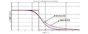
in s-plane into inside unit circle in z-plane. The main ad- vantage of this method is transform a stable designed analog filter to a stable digital filter which the frequency response has the same characteristics as frequency response of the analog filter. However, this method will give a non-linear relationship between analog frequency ωA and digital frequency ωD and leads to warping of digital frequency response.
2.1 Warping frequency and pre-warping frequency
The bilinear z-transform form the s-domain to z-domain is
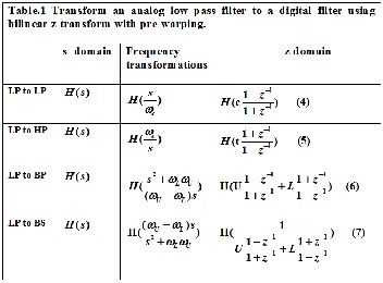
The table.1 below, illustrated converting an analog low pass filter to a low pass, high pass, band pass and band stop digital filter using bilinear z-transform with pre-warping.
defined by
21 z1

s
T 1 z1
(1)
Where T is sampling period, substitute z e sT
and s j
into equation (1), will give the relationship between ωA and ωD
as shown in equation (2) and this relationship is a non-linear [2] that causing by the ‘tan’ function and the sampling period T and this effects is called warping frequency.
2 tan T
(2)


A T 2 D
Where : c cot( fc )
t tan( fc )
When converting an analog filter to a digital filter using bilin-
ear z-transform method will give both filters have the same

fs

c cot( fU )
U f

fs

t tan( fL )
L f
s s
behaviour, but the behaviour is not matched at all the fre-
quency in s-domain and digital domain as causing by the

U cU
1 cU tL

L tL
1 cU tL
warping frequency. One way to overcome the warping fre- quency is called pre-warping frequency and it is expressed as
fs is the sampling frequency
fc is the cut off frequency ( Low pass and High pass)
f and f are the upper and lower frequency ( Band pass and Band stop)
in equation (3).
1 z 1 U L
s c
(3)
tan T
2
1 z 1
c
IJSER © 2013
http://www.ijser.org
International Journal of Scientific & Engineering Research, Volume 4, Issue 12, December-2013
ISSN 2229-5518
1975
3 BILINEAR Z-TRANSFORMATION WITH PASCAL’S
between ai, Ai and bi, Bi can be found as below
TRIANGLE
a
P
A c i
i i 0n n1;1
LP n1; n1 i
i 1n n1;1
(10)
This section introduces the bilinear z- transform with pre-
a
P
A c i
i i 0n n1;1
LP n1; n1 i
i 1n n1;1
warping to convert an analog transfer function H(s) to a digital
transfer function H(z) involved the Pascal’s triangle. With the
Pascal’s triangle, the matrix equation of the relationship be-
tween the digital coefficients and the analog coefficients can be
found easy to compute and hand-calculated.
3.1 The Pascal’s triangle
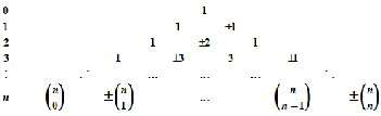
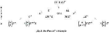
One of the most useful applications of the Pascal’s triangle is to find coefficients and expand the binomial expression (U±L)n and it can be shown in fig.1 below.
All the numbers in the matrix [PLP] can be calculated from the positive and negative Pascal’s triangle as five steps below. Step1: All the numbers in the first row of [PLP] equal to 1. (This is the left edge of the Pascal’s triangle)
Step 2: The numbers in the last row of [PLP] equal to (-1)i . (This is the right edge of the Pascal’s triangle)
Step 3: The numbers in the first column of [PLP] is the numbers in the nth row in the Pascal’s triangle, equation (8).
Step 4: The numbers in the last column of [PLP] is the numbers
in the nth row in the Pascal’s triangle, equation (10).
Step 5: Another numbers in [PLP] can be computed following expression:
PLP
i ; j
PLP
i ; j 1
PLP
i 1; j1
PLP
i 1; j
The matrix [PLP] of low pass to low pass can be rewritten as:
PLP
1
i 1; j 1n1
P
1 j 1
n1; n1
LP i n1; j 1n1
i 1n1; j 1
i 1
P P n
P
1i 1 n
LP i 1n1; j n1
i 1
IJSER
PLP
P
i ; j i ; j 1
PLP
i 1; j 1
PLP
i 1; j
n The coeffcients: i
(8)
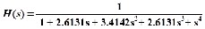
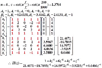
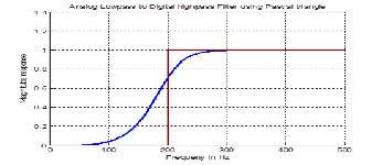
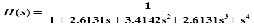
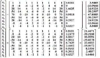
Example 1: Convert a fourth-order Butterworth analog low pass filter has the transfer function H(s), the cut-off frequency of 200hz to digital low pass filter with fs=1kHz.
U L
The exp ansion :
i o n
nU L
(9)
i 0
ni i
U Ln
The coeffcients: 1i n
i i on
n
(10)
The exp ansion : 1 U L
(11)
i 0
n ni i
i
The main key is addressed in the next sections considering the matrix equations of conversion from a low pass to low pass, high pass, band pass and band stop involved the Pascal’s tri- angle.
3.2 Convert an analog low pass filter to a digital low pass filter
The transfer function of an nth-order low pass filter in s- domain H(s) and the transfer function of a low pass filter in z- domain H(z) can be described as follow:
n
n Ai s

H ( s) A0 A1 s ... An s
i 0
n n
(8)
B0 B1 s ... Bn s A sn
i
i 0
n
a z n
a a z 1 ... a z n i
H (z) 0 1 n i 0
b b z 1 ... b z n n
i
(9)
0 1 n
i 0
b z n
Where Ai, Bi and ai , bi are all real coefficients in s-domain and z-domain respectively and n is a highest order number in the analog filter.
From equation (4), the matrix equations of the relationship
IJSER © 2013
http://www.ijser.org
International Journal of Scientific & Engineering Research, Volume 4, Issue 12, December-2013
ISSN 2229-5518
1976
3.3 Convert an analog low pass filter to a digital high pass filter
The transfer function H(z) of the digital high pass filter can be written as the equation (9) and applying the equation (5), the matrix equation can described as equation (16) blow
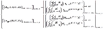
3.4 Convert an analog low pass filter to a digital band pass filter
The order of transfer function H(z) of the band pass filter is 2n, equation (12), it causes from the multiply of number 2 in s2 with the nth-order when applying the frequency transfor- mation from an nth-order low pass to a band pass filter. The
a 0
P
A t
1; 1
transfer function H(z) and the matrix equation can be written
i i n
n1;1
LP n n
i
i i 1n
n1;1
(11)
a
P
A t i
as shown below:
i i 0n
n1;1
LP n1; n1 i
i 1n n1;1 2 n
i
a z i
H ( z ) i 0
(12)
The matrix [PHP] can be found from the matrix [PLP] by swap- 2 n
i
ping the first column to the last column, the second column to
i 0
b z i
a P
A,U , L
second last column and so on or can use the formula below
i i 02 n;1 2 n1;1
BP i 12 n1; j 12 n1 2 n1;2 n1 BP
i 02 n;1 2 n1;1
(13)
PLP
1
i 1; j 1n1
bi
i 02 n;1 2 n1;1
PBP
i 12 n1; j 12 n1 2 n1;2 n1 BP
i 02 n;1 2 n1;1
P
1 j 1
The matrix [PBP] is the same with the matrix [PHP] but it has the
LP i n1; j 1n1
P
P
1i 1 n
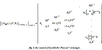
size of (2n+1; 2n+1). From equation (6) and (12), the matrix
LP
n1; n1
LP i 1n1; j 1
i 1
[ΔBP] can be found as figure.2 below
P
i 1n1; j n1
i 1
PLP
P
i ; j i ; j 1
PLP
i 1; j 1
PLP
i 1; j
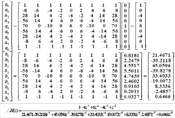
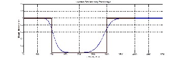
Example 2: Convert a fourth-order Butterworth analog low pass filter has the transfer function H(s), the cut-off frequency of 200hz to digital high pass filter with fs=1kHz.
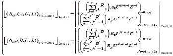
From the figure.2 above, if taking out the analog coefficient Ai in each column, the matrix [ΔBP] is the Pascal’s triangle expan-
Converting a low pass to low pass and low pass to high pass were studied. The first and last column in the matrix [PLP] and [PLP] are the nth row in the Pascal’s triangle. In the next sec- tions, it is more interesting with Pascal’s triangle to find the digital coefficients of converting low pass to band pass and band stop.
sion of (U+L)n. And from that, a formula can be derived for
the matrix [ΔBP] as shown
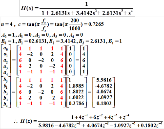
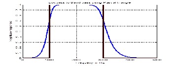
Example 3: Convert a fourth-order Butterworth analog low pass filter has the transfer function H(s) to digital band pass filter with the lower frequency fL =1 kHz, the upper frequency fU=3 kHz and the sampling frequency fs =10 kHz.
IJSER © 2013
http://www.ijser.org
International Journal of Scientific & Engineering Research, Volume 4, Issue 12, December-2013
ISSN 2229-5518
1977
3.5 Convert an analog low pass filter to a digital band stop filter
4 GENERAL FORMULA FOR CONVERTING AN ANALOG LOW PASS FILTER TO A DIGITAL FILTER
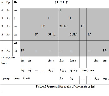
In the figuge.2, it can see that the Pascal’s triangle involved into the matrix [ΔBP] and is clearly by redraw it in table.2. The Δi is the sum of all the elements in the column of Pascal’s tri- angle multiply with the analog coefficient at the same row.
The matrix equation for converting an analog low pass to digi- tal band stop can be derived from equation (7).
The matrix [PBS] is the same the matrix [PBP]. The matrix [ΔBS] is similar with the matrix [ΔBP], the only different is the analog coefficients Ai, Bi is replaced by A and B and it can be shown as below.

Example 4: Convert a fourth-order Butterworth analog low pass filter has the transfer function H(s) to digital band stop filter with the lower frequency fL =1 kHz, the upper frequency fU=3 kHz and the sampling frequency fs =10 kHz.
From the table.2 above, if let L=0, all the elements in Pascal’s triangle have L will equal to zero, and the [Δ] becomes the matrix [ΔLP] that is the left side edge of the Pascal’s triangle. And if U=0, the [Δ] = [ΔHP] is the right side edge of the Pascal’s triangle. For the [ΔBS], the analog coefficients Ai and Bi chang- es to An-i and Bn-i. So the matrix [ΔBP] can be used for all con- verting from Lp to Lp, Lp to Hp, Lp to Bp and Lp to Bs. And the general formula for all conversion is:
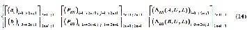
ai
i 0 N ;1 N 1;1
P
N 1; N 1 ( BS ( A,U , L))i 0 N 1;1 N 1;1
( 15)
bi
i 0 N ;1 N 1;1
P
N 1; N 1 ( BS (B,U , L))i 0 N 1;1 N 1;1
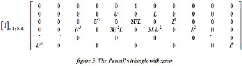
5 THE PASCAL’S TRIANGLE WITH INSERTING ZEROS

IJSER © 2013
http://www.ijser.org
International Journal of Scientific & Engineering Research, Volume 4, Issue 12, December-2013
ISSN 2229-5518
Inserting zeros into the Pascal’s triangle creates a matrix [T] as in figure.3. From table.2 the Δi is the sum of all the elements in the column of Pascal’s triangle multiply with the analog coef- ficient at the same row, it means that the matrix [Δ] can be found by matrix multiplication between matrix analog coeffi- cients with the matrix [T] as shown below
1978
( A,U , L)
(B,U , L)
A T
1; N 1 1; n1
B T
n1; N 1
(16)
1; N 1
i 1; n1
n1; N 1
The equation (16) is another way to find the coefficients of a digital filter from the coefficients of an analog low pass filter and it can be used to invert from the coefficients of a digital filter to the coefficients of a low pass filter. The inverting of a digital filter to an analog low pass filter will be presented in the next paper “Transform a digital filter to another digital filter using Pascal’s triangle”.
6 CONCLUSION
In this work, the bilinear z-transform is used to convert an transfer function H(s) of an analog low pass to the transfer function H(z) of a digital filter and vice versa. The involving of the Pascal’s triangle made both the direct and inverse trans- formation easier for computing and hand-calculated. And all the formulas are derived and demonstrated. It would be the powerful tools in using all these formulas for converting ana- log to digital and from digital to analog filter.
REFERENCES
[1] Emmanuel C. Ifeacor, Barrie W. Jervis. (1993). Digital Sig- nal Processing. Addison-Wesley, USA
[2] Konopacki J. (2005). The frequency Transformation by Ma- trix Operation and its Application in iir Filters Design. IEEE Signal Processing Letters, Vol. 12, No.1, pp.5-8, January.
[3] B.P.eni.ka (2007). Practical Design of Digital Filters Using the Pascal Matrix. Ingenieria Investigation of Technology VIII.3. pp 197-210.
[4] F. J. Garcia-Ugalde. (2011). Z-transform by Pascal Matrix and its Applications in the Design of IIR Filters. IEEE, vol.9, N0.3, pp.355-366, December.
[5] Chivapreecha, S. (2005). Bilinear s-z frequency transfor- mation using matrix Pascal operation, IEEE, Communications and Information Technology, Vol.1, pp 764-767.
IJSER © 2013
http://www.ijser.org