International Journal of Scientific & Engineering Research, Volume 5, Issue 7, July-2014 935
ISSN 2229-5518
Backpressure Algorithm Technique a Tool to
Improving Congestion Control in Data
Communication Network.
EKWE O.A*, EMOLE, E. C. **
Department of Electrical/Electronics Engineering, Michael Okpara University of Agriculture, Umudike, Abia State, Nigeria.
ogbonnaekwe@gmail.com ,
Department of Electrical/Electronics Engineering, Michael Okpara University of Agriculture, Umudike, Abia State, Nigeria.
emekaemole@gmail.com
—————————— ——————————
I. INTRODUCTION
N recent years, we have experienced rapid evolution of networking services and increase in long distance traffic intensity in data communication systems. Modern data transmission networks are expected to provide high-throughput, low-jitter end-to-end
connectivity, important for video streaming, remote visualization and steering, or Internet telephony.
However, all of these can only be achieved if the available resources are administered in a coordinated manner, according to dynamically changing networking conditions (varying traffic intensity, number of active connections, buffer levels, etc.). If the network load increases beyond the channel capacity, congestion occurs, and data fills the buffers at the network nodes, eventually leading to packet discards and retransmissions. If, on the other hand, the traffic intensity excessively drops, then only part of the available bandwidth at the intermediate links is used for the data transfer [1]. Therefore, in order to combat the congestion and at the same time ensure high throughput in the network, it is not sufficient to merely extend the physical channel capacity, introduce connections with higher baud rates, or install faster transceivers. A successful solution to the dynamical resource allocation problem must involve the use of appropriate flow control mechanisms, which will guarantee stable and efficient network operation.
The goal of congestion control is to avoid congestion in network elements. Congestion control refers to the mechanisms and techniques that can either prevent congestion, before it happens, or remove congestion after it has happened and keep the load below the capacity. The control resources include: routers CPUs, bandwidth of links, routers memory, etc. If we don’t control our network, there is potential for a serious trouble; users don’t receive expected packets (or conformation of delivery) in the time limit. Users begin to resubmit packets and new packets cause further congestion. Some packets are lost and the elements can’t offer high-speed service to users.
In general, congestion control mechanisms are divided into two broad categories: open loop congestion control (prevention) and
closed-loop congestion control (removal). The mechanism of control usually works in the following way [2]. The system monitors various factors (e.g. router’s CPU occupancy, link occupancy, percent of delivered packets, messaging delays, etc.). Based on this information the system detects possible congestion. If the system has detected an incipient congestion, it restricts traffic rates in some network elements and continues to monitor the state of the network. This activity reduces traffic through these elements. When elements will have been unloaded, the system will restore normal traffic rates in these elements.
To control or remove the congestion we can use many congestion control techniques like Adaptive, Choke packet, Backpressure, etc.
II .BACKPRESSURE
Backpressure technique is a method of flow control used in data communications systems, used on communication links between data communications systems, and also for communications between subsystems of data communications systems. Generally, the purpose of backpressure signaling is to prevent packet loss at receiver queues caused by overflowing those queues.
The legacy of backpressure techniques is that it employs simple on-off signaling. According to this technique, a receiver queue of a data communications system, upon crossing a fill-level threshold causes a backpressure signal (e.g. halt) to be generated that is sent to the source of the packets as shown in figure 1.
IJSER © 2014 http://www.ijser.org
International Journal of Scientific & Engineering Research, Volume 5, Issue 7, July-2014 936
ISSN 2229-5518
Backpressure
![]()
![]()
I II III IV
![]()
![]()
Congestion
Data flow
The backpressure signal (halt) indicates to the source that it should suspend sending packets to that queue until further notice, which will be given in the form of another backpressure signal (e.g. resume) [3]. In some cases there can be more than one packet source, and in those cases the backpressure signal would normally be sent to all of those sources. This technique has been highly successful in communications systems because it is simple to implement; requiring only a limited amount of information to be sent back to the transmitting source to process.
More advanced backpressure techniques are known that offer more than simple on-off signaling. These include techniques employing progressive throttling of a packet flow to a queue as successively higher fill-level thresholds are exceeded at the queue. Other techniques have means for applying backpressure to packets of only certain priorities. Generally, more advanced backpressure techniques require more information to be sent back to a packet source via advanced backpressure signaling.
The algorithm is a well-known throughput-optimal algorithm and its implementation requires that each node has to maintain a separate queue for each commodity in the network, and only one queue is served at a time. [4].
Backpressure algorithm operates in slotted time where in every time slot it seeks to route data in directions that maximize the differential backlog between neighboring nodes. This is similar to how water flows through a network of pipes via pressure gradients. However, the backpressure algorithm can be applied to multi-commodity networks (where different packets may have different destinations), and to networks where transmission rates can be selected from a set of (possibly time-varying) options and may be difficult to implement exactly in networks with interference.
Attractive features of the backpressure algorithm include:
1. It leads to maximum network throughput,
2. It is provably robust to time-varying network conditions,
3. It can be implemented without knowing traffic arrival rates or channel state probabilities.
Backpressure networks are susceptible to three important problems:
1. Lack of fairness,
2. Unnecessary spread of backpressure signals to more than one hop in reverse direction and,
3. The possibility of deadlocks (a condition in which throughput of the network or part of the network goes to zero.
This fact may lead to a poor delay performance even when the traffic load is not close to network capacity [5]. Also, since the number of commodities in the network is usually very large, the queuing data structure has to be maintained at each node is respectively complex.
III. MATERIAL AND METHODS The precise mathematical development of this technique is described in this section.
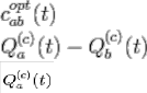
A. Optimal Commodity ![]() Determination
Determination
Consider node a, observing its own queue backlogs and the backlogs in its current neighbors in an N nodes link. If current neighbor of node a, is a node b such that it is possible to choose a non-zero transmission rate ![]() on the current slot. Thus, neighbors are determined by the set δ S (t) such that a node can have all N − 1 other nodes as neighbors. However, sets δ S(t) preclude transmissions between nodes that are separated by more than a certain geographic distance, or that would have propagated signal strength below a certain threshold [6]. Thus, it is typical for the number of neighbors to be much less than N − 1. The set of neighbors of a given node determines the set of outgoing links it can use for transmission on the current slot. For the outgoing links (a, b), the optimal commodity
on the current slot. Thus, neighbors are determined by the set δ S (t) such that a node can have all N − 1 other nodes as neighbors. However, sets δ S(t) preclude transmissions between nodes that are separated by more than a certain geographic distance, or that would have propagated signal strength below a certain threshold [6]. Thus, it is typical for the number of neighbors to be much less than N − 1. The set of neighbors of a given node determines the set of outgoing links it can use for transmission on the current slot. For the outgoing links (a, b), the optimal commodity
is defined as the commodity; C ε{1…..N} that has maximum differential backlog quantity given by the equation:
……………….. (1), where;
; is queue blocking of node a; and
IJSER © 2014 http://www.ijser.org
International Journal of Scientific & Engineering Research, Volume 5, Issue 7, July-2014 937
ISSN 2229-5518
![]() ; is queue blocking of node b
; is queue blocking of node b
B. Transmission Rate ![]() Matrix
Matrix

Having the optimal commodities determined for each link (a, b), the network controller computes the following weights ![]() :
:
…………….. (2)
Where the weight is the value of the differential backlog associated with the optimal commodity for link (a, b), maxed with
0. The controller then chooses transmission rates as the solution to the following max-weight problem (breaking ties arbitrarily).
The backpressure control decisions
Backpressure controller observes S (t) and performs the following 3 steps: First, for each link (a, b); it selects an optimal commodity ![]() to use. Next, it determines what
to use. Next, it determines what ![]() matrix in δ S (t) to use.
matrix in δ S (t) to use.
Finally, it determines the amount of commodity ![]() it will transmit over link (a, b) (being at most
it will transmit over link (a, b) (being at most ![]() , but possibly being
, but possibly being
less in some cases)
C. Routing variables
Since the optimal commodities ![]() have been determined for each link, and the transmission rates
have been determined for each link, and the transmission rates ![]() have also been determined. If the differential backlog for the optimal commodity on a given link (a, b) is negative, then no data is transferred over this link on the current slot. Else, the network offers to send
have also been determined. If the differential backlog for the optimal commodity on a given link (a, b) is negative, then no data is transferred over this link on the current slot. Else, the network offers to send ![]() units of commodity
units of commodity ![]() data over this link. This is done by defining routing variables
data over this link. This is done by defining routing variables ![]() variable for each link (a, b), and each commodity c, where: the value of
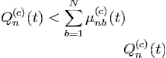
variable for each link (a, b), and each commodity c, where: the value of ![]() represents the transmission rate offered to commodity c data over link (a, b) on slot t. However, nodes might not have enough of a certain commodity to support transmission at the offered rates on all of their outgoing links [7]. This arises on slot t for node n and commodity c if:
represents the transmission rate offered to commodity c data over link (a, b) on slot t. However, nodes might not have enough of a certain commodity to support transmission at the offered rates on all of their outgoing links [7]. This arises on slot t for node n and commodity c if:
………………….. (3)
In this case, all of the data is sent, and null data is used to fill the unused portions of the offered rates, allocating the actual data and null data arbitrarily over the corresponding outgoing links (according to the offered rates). This is called a queue underflow situation. Such underflows do not affect the throughput or stability properties of the network. Intuitively, this is because underflows only arise when the transmitting node has a low amount of backlog, which means the node is not in danger of instability.
D. Backpressure Distributing
The transmission rates ![]() have been selected; the routing decision variables
have been selected; the routing decision variables ![]() can be computed in a simple distributed manner, where each node only requires knowledge of queue backlog differentials between itself and its neighbors. However, selection of the transmission rates requires a solution to the max-weight for non interference network.
can be computed in a simple distributed manner, where each node only requires knowledge of queue backlog differentials between itself and its neighbors. However, selection of the transmission rates requires a solution to the max-weight for non interference network.
For interference networks with link rates that are determined by the signal-to-noise-plus-interference ratio (SINR) can be carried out using randomization. Each node randomly decides to transmit every slot t (transmitting a "null" packet if it currently does not have a packet to send). The actual transmission rates, and the corresponding actual packets to send, are determined by a 2-step handshake: first step, the randomly selected transmitter nodes send a pilot signal with signal strength proportional to that of an actual transmission. The second step, all potential receiver nodes measure the resulting interference and send that information back to the transmitters.
The SINR levels for all outgoing links (n, b) are then known to all nodes n, and each node n can decide its ![]() and
and ![]() variables based on this information. The resulting throughput is not necessarily optimal. However, the random transmission process can be viewed as a part of the channel state process (provided that null packets are sent in cases of underflow [8], so that the channel state process does not depend on past decisions). Hence, the resulting throughput of this distributed implementation is optimal over the class of all routing and scheduling algorithms that use such randomized transmissions.
variables based on this information. The resulting throughput is not necessarily optimal. However, the random transmission process can be viewed as a part of the channel state process (provided that null packets are sent in cases of underflow [8], so that the channel state process does not depend on past decisions). Hence, the resulting throughput of this distributed implementation is optimal over the class of all routing and scheduling algorithms that use such randomized transmissions.
IV. RESULT AND DISCUSSION
IJSER © 2014 http://www.ijser.org
International Journal of Scientific & Engineering Research, Volume 5, Issue 7, July-2014 938
ISSN 2229-5518
The example in Fig. 2 illustrates neighbors by link connections, so that node A has neighbors B and C. The example suggests a symmetric relationship between neighbors (so that if A is a neighbor of B, then B is a neighbor of D), but this need not be the case in general.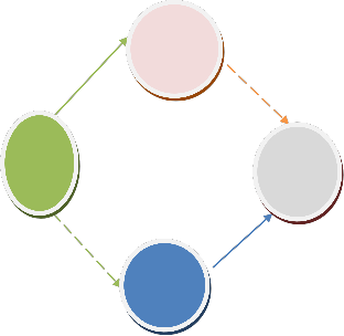
Consider a multi-hop network with N nodes. Assuming slotted time, the basic idea of backpressure scheduling is to select a set of non interfering links for transmission at each slot. We now describe this idea in a 4 node network with two flows from node A to D, depicted in Figure 1. Assume that we have two link sets, {(A, B), (C, D)} and {(A, C), (B, D)}, shown as continuous and dashed lines. The links in each set do not interfere and can transmit in the same time slot. Each node maintains a separate queue for each flow [9]
5
B 1
5 3
4 3 D
7
2
Links in sets {(A, B), (C, D)} (dashed) and {(A, C), (B, D)} (continuous) can be scheduled in the same slot.
The scheduler executes the following three steps at each slot. First, we find for each link the flow with the maximum differential queue backlog, e.g., for link (A, B), the black flow has the maximum of 3 packets. This value is then assigned as the weight of the link. In the second step, we select the set of non-interfering links for transmission. To do this, we first compute the sum of link weights for each possible set. In our case, set {(A, B), (C, D)} sums to 2+5 = 7 and set {(A, C), (B, D)} sums to 4+5 = 9. The schedule then selects the set with the maximum sum of weights, i.e., {(A, C), (B, D)}, to transmit at this slot.
V. CONCLUSION
Presence of backpressure mechanisms in data communication network responds to congestion signal by reducing the load it generates and tries to match the available capacity of the network in order to alleviate the congestion status. This will keep the source rates well informed of the achievable rate, and avoid congestion collapse, aimed at preventing a fast sender from overwhelming a slow receiver. The control technique can take place at many levels:
User process to user process (end-to-end), e.g. TCP uses the flow control at the end-to-end level.
Host to host. For example, if multiple application connections share a single virtual circuit between two hosts.
Router to router. E.g. in virtual circuit
REFERENCES
[1]M. J. Neely; Stochastic Network Optimization with Application to Communication and Queuing Systems, Morgan & Claypool,
2010.
[2] Jain, R. “Myths about Congestion Management in High-Speed Networks.” Internetworking: Research and Experience, Volume 3,
1992.
IJSER © 2014 http://www.ijser.org
International Journal of Scientific & Engineering Research, Volume 5, Issue 7, July-2014 939
ISSN 2229-5518
[3] Dina Katabi, Mark Handley, and Chalrie Rohrs, “Congestion Control for High Bandwidth-Delay Product Networks,” in
Proceedings of ACM Sigcomm, 2002.
[4] F. P. Kelly, A. Maulloo, and D. Tan, “Rate control for communication networks: shadow prices, proportional fairness and stability,” J. Oper. Res. Soc., vol. 49, no. 3, pp. 237-252, Mar. 1998.
[5] R. Gallager, S.J. Golestani, Flow control and routing algorithms for data networks, in: Proceedings of the 5th International Conf. Computer Communications, 1980, pp. 779–784.
[6] S. Floyd, M. Allman; Specifying New Congestion Control Algorithms. RFC5033. 2007.
[7]A. Stolyar, "Maximizing Queuing Network Utility Subject to Stability: Greedy Primal-Dual Algorithm," Queuing Systems, vol. 50, no. 4, pp. 401-457, 2005.
[8] Y. Zhang, D. Leonard, D. Loguinov, Jetmax: scalable max–min congestion control for high-speed heterogeneous networks, Elsevier Computer Networks 52 (6) (2008).
[9]V. Jacobson and M. Karels, “Congestion avoidance and control,” in Proceedings of SIGCOMM’88, Stanford, CA, Aug. 1988. AUTHORS BIOGRAPHY
Engr. EKWE O. A. is a lecturer at Michael Okpara University of Agriculture, Umudike. He obtained his Bachelor of Engineering (B.Eng.) degree in Electronics Engineering at the University of Nigeria, Nsukka in 2005, and a Master’s Degree in Electronic Communications and Computer Engineering from University of Nottingham, United Kingdom in 2011. His research interest are in the areas of Interference management for cellular communication, Communication techniques for next generation cellular systems, Channel fading mitigation for fixed and mobile wireless communication systems, etc.
EMOLE, E.C. B. Eng. is a Postgraduate Student of Electrical/Electronic Engineering, Michael Okpara University of Agriculture, Umuahia, Abia State, Nigeria. He holds a B.Eng. (Hons) in Electrical/Electronics. His research interests include Electronic and Digital Systems, Data Communication, Radar System etc.
article guides a stepwise walkthrough by Experts for writing a successful journal or a research paper starting from inception of ideas till their publications. Research papers are highly recognized in scholar fraternity and form a core part of PhD curriculum. Research scholars publish their research work in leading journals to complete their grades. In addition, the published research work also provides a big weight-age to get admissions in reputed varsity. Now, here we enlist the proven steps to publish the research paper in a journal.
Identify the constructs of a Journal – Essentially a journal consists of five major sections. The number of pages may vary depending upon the topic of research work but generally comprises up to 5 to 7 pages. These are:
1) Abstract
2) Introduction
3) Research Elaborations
4) Results or Finding
5) Conclusions
II. IDENTIFY, RESEARCH AND COLLECT IDEA
It's the foremost preliminary step for proceeding with any research work writing. While doing this go through a complete thought process of your Journal subject and research for it's viability by following means:
1) Read already published work in the same field.
2) Goggling on the topic of your research work.
3) Attend conferences, workshops and symposiums on the same fields or on related counterparts.
4) Understand the scientific terms and jargon related to your research work.
III. WRITE DOWN YOUR STUDIES AND FINDINGS
Now it is the time to articulate the research work with ideas gathered in above steps by adopting any of below suitable approaches:
IJSER © 2014 http://www.ijser.org
International Journal of Scientific & Engineering Research, Volume 5, Issue 7, July-2014 940
ISSN 2229-5518
A. Bits and Pieces together
In this approach combine all your researched information in form of a journal or research paper. In this researcher can take the reference of already accomplished work as a starting building block of its paper.
Jump Start
This approach works the best in guidance of fellow researchers. In this the authors continuously receives or asks inputs from their fellows. It enriches the information pool of your paper with expert comments or up gradations. And the researcher feels confident about their work and takes a jump to start the paper writing.
B. Use of Simulation software
There are numbers of software available which can mimic the process involved in your research work and can produce the possible result. One of such type of software is Matlab. You can readily find Mfiles related to your research work on internet or in some cases these can require few modifications. Once these Mfiles are uploaded in software, you can get the simulated results of your paper and it easies the process of paper writing.
As by adopting the above practices all major constructs of a research paper can be written and together compiled to form a complete research ready for Peer review.
IV. GET PEER REVIEWED
Here comes the most crucial step for your research publication. Ensure the drafted journal is critically reviewed by your peers or any subject matter experts. Always try to get maximum review comments even if you are well confident about your paper.
V. IMPROVEMENT AS PER REVIEWER COMMENTS
Analyze and understand all the provided review comments thoroughly. Now make the required amendments in your paper. If you are not confident about any review comment, then don't forget to get clarity about that comment. And in some cases there could be chances where your paper receives number of critical remarks. In that cases don't get disheartened and try to improvise the maximum.
This completes the entire process required for widespread of research work on open front. Generally all International Journals are governed by an Intellectual body and they select the most suitable paper for publishing after a thorough analysis of submitted paper. Selected paper get published (online and printed) in their periodicals and get indexed by number of sources.
VI. CONCLUSION
A conclusion section is not required. Although a conclusion may review the main points of the paper, do not replicate the abstract as the conclusion. A conclusion might elaborate on the importance of the work or suggest applications and extensions.
Appendixes, if needed, appear before the acknowledgment.
APPENDIX
ACKNOWLEDGMENT
The preferred spelling of the word “acknowledgment” in American English is without an “e” after the “g.” Use the singular heading even if you have many acknowledgments.
REFERENCES
[1] G. O. Young, “Synthetic structure of industrial plastics (Book style with paper title and editor),” in Plastics, 2nd ed. vol. 3, J. Peters, Ed. New York: McGraw-Hill, 1964, pp. 15–64.
[2] W.-K. Chen, Linear Networks and Systems (Book style). Belmont, CA: Wadsworth, 1993, pp. 123–135. [3] H. Poor, An Introduction to Signal Detection and Estimation. New York: Springer-Verlag, 1985, ch. 4.
[4] B. Smith, “An approach to graphs of linear forms (Unpublished work style),” unpublished.
IJSER © 2014 http://www.ijser.org
International Journal of Scientific & Engineering Research, Volume 5, Issue 7, July-2014 941
ISSN 2229-5518
[5] E. H. Miller, “A note on reflector arrays (Periodical style—Accepted for publication),” IEEE Trans. Antennas Propagat., to be published.
[6] J. Wang, “Fundamentals of erbium-doped fiber amplifiers arrays (Periodical style—Submitted for publication),” IEEE J. Quantum Electron., submitted for publication.
AUTHORS
IJSER © 2014 http://www.ijser.org