Using electrostatic for line charge,
International Journal of Scientific & Engineering Research, Volume 3, Issue 3, March-2012 1
ISSN 2229-5518
Axisymmetric Excited Integral Equation Using
Moment Method for Plane Circular disk
Praveen Kumar Malik Member IEEE, Harish Parthasarthy Member IEEE, M P Tripathi
Abstract—Calculating current distribution is a common problem in antenna. It significantly affects the operation of almost all type of antenna. There have been many different methods suggested to derive the equation for impedance and current distribution so far. In this paper, integral equation using numerical technique for plane circular surface is investigated. An expression for the current distribution
plate type antenna elements. The integral equation is then solved for the unknown induced current density using numerical techniques such as the method of moment (M.O.M).
II. DESIGN PROCEDURE
A circular ring of radius a carries a uniform charge and is placed on X-Y plane with axis on Z axis.
Using electrostatic for line charge,![]()
L C/m
E
![]()
L dl a R
(1)
I. INTRODUCTION
HE impedance of an antenna depends on many factors like its operating frequency, geometry, method
of excitation, and proximity to the surrounding objects. Due to geometries, only few antennas have been investigated theoretically. Impedance of an antenna at a point is defined as the ratio of the electric to the magnetic fields at that point; alternatively at a pair of terminals, it is defined as the ratio of the voltage to the current across those terminals also[1]. There are few methods that can be used to calculate the current distribution of an antenna.
(1) Boundary-value method (2) Transmission line method (3) Poynting vector method
Most basic approach is the boundary-value method. The solution to this is obtained by enforcing the boundary
L 4 0 R
In this case,![]()
dl ad
R a(a ) ha z
(2)
conditions (Tangential electric-field components vanish at the conducting surface). Impedance of an antenna can also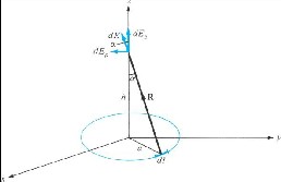
![]()
Fig. 1. Evaluation of E field due to charged ring of radius a.
1/ 2
be found using an integral equation with a numerical technique solution, which is referred to as the integral equation method of moments[2] which cite the solution for
Let,
R R a2 h2 (3)
R
the induced current in the form of an integral equation. This method includes electromagnetic problems which is![]()
a R
![]()
R
analytically simple, but requires large computation. In this paper the integral equation method, with a Moment Method numerical solution, will be introduced and used to calculate![]()
![]()
a R R R2 R3
![]()
aa ha z
a2 h2
(4)
the impedance and current distribution of circular plate. This
approach is very general, and it can be used with today’s![]()
Therefore, field E will be,![]()
2
modern computational methods and equipment to compute
E L
(aa ha z ) ad
(5)
the characteristics of complex configurations of circular![]()
4 0
0
![]()
a
2 h2
3/ 2
[3]
![]()
Mr. Praveen Kr. Malik is with the Electronics and Communication department, Radha Govind Engineering College, Meerut UP, INDIA (e- mail: malikbareilly@gmail.com).
Prof. Harish Parthasarthy is with the Electronics and Communication department, NSIT, New Delhi, INDIA (e-mail: harishp@nsit.ac.in)
Prof. M P Tripathi is with the Electronics and Communication
department, M.A.I.T, Ghaziabad, INDIA (e-mail:
munishprashadtripathi@rediffmail.com)
By symmetry, the contribution along a add up to zero .
This is evident from the fact that for every element dl , there is a corresponding element diametrically opposite that gives an equal but opposite dE so that the two contributions cancel each other. Thus we are left with the z component. That is,
Praveen Kumar Malik Member IEEE, Harish Parthasarthy Member IEEE, M P Tripathi
International Journal of Scientific & Engineering Research, Volume 3, Issue 3, March-2012 2
ISSN 2229-5518
![]()
E L aha z
![]()
2
d
![]()
4 0
E ( 0,0,h )
![]()
h2 a2 3/ 2
L aha z
2 2
![]()
0
![]()
3/ 2
(6)
2 0 h
a
For maximum value of E , h will be,![]()
h2 a2 3/ 2 3 2h2 h2 a2 1/ 2
![]()
d E
L 2
dh 2
h2 a2 3
![]()
For Maximum E,
(7)
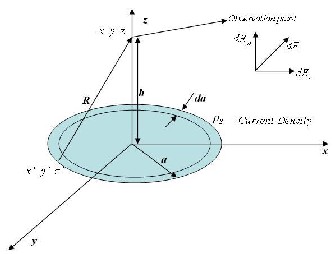
d E Fig. 2. Evaluation of E field due to charged circular surface of radius a.
0
dh Similarly for a circular disk of radius a uniformly charged
This implies that
with
C/m2. The disk lies on the z=0 plane with its axis
h2 a2
h2 a2 3h2 0
along the z axis. One can calculate the E field as specified above.
a2 2h2 0
Or![]()
h
s
![]()
E (0,0,h)
![]()
2
1
1/ 2 a z
(11)
h a
(8)
0 h
a
2
Let the charge is uniform distributed on the circular plate, the charge density is,
Q
For far field calculation, h>>a, therefore, potential at (0,0,h)
will be,
![]()
L
2 a
V(0,0,h)
![]()
h.s 1
![]()
h
2 2
1/ 2
(12)![]()
So that,
2 0
h a
![]()
E Qh
2 2
3/ 2 a z
(9)
Let us assume the unknown charge distribution
s by an
4 0 h
a
expansion of K known terms with constant, but unknown, coefficients, that is[5],![]()
As if a 0
K
c g
(13)![]()
E Q a
s i i i 1
4 0 h
![]()
In general,
Q
The circular disk of radius a, is divided into k uniform ring,
each of width ζ = a/k. To obtain a solution for these k amplitude constants, k linearly independent equations are required. These equations may be produced by choosing k![]()
E a R
4 0 r
(10)
observation points each at the center of each ζ length
element[6]. To avoid complexity in this solution, sub domain
Which is the same as that of point charge, as one would
expect?
III. MATHEMATICAL FORMULATION
piecewise constant functions will be used. These functions, are defined to be of a constant value over one segment and zero else where, or
1 0 x ' a
The target of the Integral Equation (IE) method for antenna is to cite the solution for the unknown current density[4],
gi ( X ')
0
x ' a
which is induced on the surface of the antenna, in the form
of an integral equation where the unknown induced current density is part of the integrand. Potential due to a given charge distribution is considered in electrostatics, and now we know that a linear charge distribution creates an electric
potential due to ring of radius a .
Corresponding to each observation point, For K such points,
we can reduce 12 to
Praveen Kumar Malik Member IEEE, Harish Parthasarthy Member IEEE, M P Tripathi
International Journal of Scientific & Engineering Research, Volume 3, Issue 3, March-2012 3
ISSN 2229-5518
![]()
2 c
(h
g a
1( X ') da ..... c
a2 )
(h2
![]()
gK ( X ') da
a2 )3/ 2
[2] Leonard L. Tsai, Charles e. Smith, "Moment Methods in Electro magnetic for under graduates", IEEE Transactions on Education, vol. e-21, no. 1, February 1978
0 1( X ')
1( x ')
( K 1)
a
1( X ')
g
K ( x ')
[3] Antenna theory, analysis and synthesis, “Advanced signal analysis and its applications to mathematical physics”, Harish Parthasarthy, page 560-571 (I K International publication) 2009.
[4] J.J.H. Wang, PhD "Generalized moment methods in electro magnetic", IEEE proceedings, vol.137, pt. H, no. 2, April 1990.
[5] Constantine A. Balanis, “Antenna Theory”: Analysis and design, John
![]()
Wiley & sons, New Delhi, 2008.
![]()
2 c
0
K ( X ')
da .... c
a2 )3/ 2 K
( K 1)
(h2
K ( X ')
da
a2 )3/ 2 [6] Umashankar, K., Nimmagadda, S.. “Application of integral equation
and method of moments for electrically very large scatterers using
spatial decomposition technique”, IEEE Antennas and Propagation
(14)
We may write equation (14) more concisely using matrix notation as[7-8]
Society International Symposium, 7-11 May 1990, pp 76-79 Vol 1.
[7] Electromagnetism and relativity theory, “Application of advance signal analysis”, Harish Parthasarthy, page 441-507 (I K International publication) 2008.
[8] Mishra, M., Gupta, N. “Integration Technique in Method of Moments
Vm Zmn In
Where Zmn, is
a
Z K ( X ') da
(15)
(16)
solution of Integral equation”, IEEE Applied Electromagnetics
Conference at Kolkata, 19-20 Dec. 2007, pp 1-4.
[9] Fuscon, “Fundamental of Antenna Theory and Technique” Pearson
Education, New Delhi 2011.
![]()
mn
2 2 3/ 2
0 (h K ( X ') a )
If we compare eq. 15 with eq. 16,
In CK
Vm 2 0
TABLE I DESCRIPTION FOR QUANTITY USED
![]()
![]()
0
The Vm column matrix has all terms equal to 2 0 , and the
In CK values are the unknown charge distribution
coefficients. Solving 15 for In gives
Elevation angle
Azimuthal angle 0 2
Q Charge C 1.6x10⁻¹⁹ C
E Electrical field N C-1
I C
Z
1 V
(17)
Permittivity of -1
0 Vacuum 8.85 pF m
Equation 17 may be solved on a computer by using any of a number of matrix inversion routines[9]. The integral involved
Observation point
distance In meter
a Radius of circular plate In meter
Permeability 1 4 10
H/m
here can be evaluated in closed form by making appropriate approximations. Efficient numerical integral computer
= 4 107 Wb/(A·m)
r Relative permeability r
subroutines are commonly available in easy-to-use forms.
IV. CONCLUSION
In this paper, we have applied the M.O.M for plane circular type antenna. The integral equation for a thin circular plate is derived, some properties of integral equation are presented and are utilized to reduce the computation of integral equation to some sparse matrix notation. The method is computationally attractive, and mathematically formulation is demonstrated through illustrative example.
ACKNOWLEDGMENT
Author would like to thanks Prof. Harish Parthsarthy, department of Electronics and Communication, N.S.I.T, New Delhi for all his support. I am grateful for the encouragement of Prof. M P Tripathi, Retd. Prof. NSIT, New Delhi, that made me write and publish paper. The author will also like to express sincere appreciation and gratitude to department of Electronics and Communication, Radha Govind Engineering College, Meerut UP India, which has provided tremendous assistance throughout the work.
REFERENCES
[1] Kraus J D, “Elements of Electromagnetic” McGraw-Hill, New Delhi
3rd edition, 2010.
Praveen Kumar Malik Member IEEE, Harish Parthasarthy Member IEEE, M P Tripathi