The research paper published by IJSER journal is about Area Reduction and Doubling the Speed of FIR Filter using VHDL 1
ISSN 2229-5518
Area Reduction and Doubling the Speed of FIR Filter using VHDL
K.V.N.M.Brahmanandam, V.Satya Deepthi, P.Durga Bhavani, U.Prathibha, M.Mani Divya
Abstract: The Finite Impulse Response (FIR) filter is a digital filter widely used in Digital Signal Processing applications in various fields like maging, instrumentation, and communications. This work proposes an VHDL generation software for FIR filters. In this paper a near alg orithm for constant coefficient FIR filters was used. This algorithm uses general coefficient representation for the sharing of partial products in Multiple Constants Multiplications (MCM). The FIR filter is simulated with the help of Xilinx ISE (Integrated Software Environment). Codes for d irect form fixed point FIR filter have been realized. Modules such as multiplier, adder, ram and two’s compliment were used. For an N order filter the number of shift registe r and adders required is N and the number of multipliers required is N+1.These filters can work in real time. The software produces a generic VHDL output, synthesizable to FPGA.
—————————— ——————————
In signal processing, the function of a filter is to
remove unwanted parts of the signal, such as random noise, or to extract useful parts of the signal, such as the components lying within a certain frequency range. The main drawback of FIR filters is the amount of computation needed to process a signal through a FIR filter. The most expensive operators in terms of area, delay and power in a FIR filter structure are the multipliers. An analog filter uses analog electronic circuits made up from components such as resistors and capacitors to produce the required filtering effect. Such filter circuits are widely used in such applications as noise reduction, signal enhancement, and many other areas. A digital filter uses a digital processor to perform numerical calculations on sampled values of the signal. The processor may be a general-purpose computer such as a PC, or a specialized DSP (Digital Signal Processor) chip. In fact, the problem of designing FIR filters has received significant attention during the last decade and many algorithms have been proposed to minimize the number of addition/subtraction operations.
————————————————
![]() V nm Brahnamamdam K is currently pursuing masters degree program in
V nm Brahnamamdam K is currently pursuing masters degree program in
VLSI and SYSTEM DESIGN in KIET,INDIA, PH-09290058990.
E-mail:mailme_brahmi@yahoo.com
In signal processing, there are many instances in which an input signal to a system contains extra unnecessary content or additional noise which can degrade the quality of the desired portion. In such cases we may remove or filter out the useless samples. There are two basic types of digital filters, Finite Impulse Response (FIR) and Infinite Impulse Response (IIR) filters. We had access to the source code of the original implementation that facilitates its adoption in the proposed software tool. The generated VHDL code is generic and can be synthesized using any common synthesis tool. The proposed tool was validated by synthesizing a set off FIR filters benchmarks and comparing its implementation results with the implementations generated by Matlab Filter Design and Analysis. we conclude this paper, discussing the main contributions and future work.
We have implemented three modules in our work:
2.1) D-flip-flop
2.2) RAM
2.3) Mac
The D flip-flop tracks the input, making transitions with match those of the input D. The D stands for "data"; this flip-flop stores the value that is on the data line. It can be thought of as a basic memory cell. A D flip- flop can be made from a set/reset flip-flop by tying the set to the reset through an inverter. The result may be clocked.
IJSER © 2012 http://www.ijser.org
The research paper published by IJSER journal is about Area Reduction and Doubling the Speed of FIR Filter using VHDL 2

ISSN 2229-5518
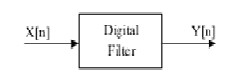
Fig. 2 FIR Functional block
Fig. 1 D-Flip flop
The above figure implements the below equation:![]()
Random access memory (RAM) is a form of
computer data storage. Today, it takes the form of integrated circuits that allow stored data to be accessed in any order with a worst case performance of constant time. Strictly speaking, modern types of DRAM are therefore not random access, as data is read in bursts, although the name DRAM / RAM has stuck. However, many types of SRAM, ROM, OTP, and NOR flash are still random access even in a strict sense. RAM is often associated with volatile types of memory (such as DRAM memory modules), where its stored information is lost if the power is removed. Many other types of non-volatile memory arise RAM as well, including most types of ROM and a type of flash memory called NOR-Flash. The first RAM modules to come into the market were created in 1951 and were sold until the late
1960s and early 1970s.
In computing, especially digital signal processing, the multiply–accumulate operation is a common step that computes the product of two numbers and adds that product to an accumulator. The hardware unit that performs the operation is known as a multiplier– accumulator (MAC, or MAC unit); the operation itself is also often called a MAC or a MAC operation. The MAC operation modifies an accumulator a:![]()
In digital circuits, a FIR (Finite Impulse Response)filter can be viewed as a functional block, as shown in figure: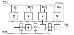
where N is the number of coefficients (or taps) of the filter, X is the input signal, Y the output signal, Y[n] the current output sample and H represents the filter coefficients. The coefficients of the FIR filter are obtained using the Discrete Fourier Transform (DFT) of the required frequency transfer function with some known windowing method. In this work we will use a fully-parallel implementation of FIR filters. In particular, we will explore the transposed form architecture, as shown in Fig. 3. This architecture involves multiplying all the coefficients by the same input data. Because registers are now between the adders, the resulting circuit is faster, since critical path is smaller. Moreover, due to register localization most of the glitching activity is filtered, resulting in a significant power reduction.
Fig. 3 4-tap FIR FILTER
Common optimization strategies explore the fact that the FIR filter multiplications can be implemented by sharing partial results/terms through the adders/subtractors circuit tree that implements the MCM block.
Very High Speed Integrated Circuit Hardware Description Language (VHDL) is used as the designing language. Hardware Description Languages (HDLs) are used to describe the behavior and structure of system and circuit designs. VHDL stands for Very High Speed Integrated Circuits (VHSIC) Hardware Description Language (HDL).
IJSER © 2012 http://www.ijser.org
The research paper published by IJSER journal is about Area Reduction and Doubling the Speed of FIR Filter using VHDL 3
ISSN 2229-5518
It is a language for describing digital electronic systems. It was born out of United States Government’s VHSIC program in 1980 and was adopted as a standard for
describing the structure and function of Integrated Circuits (ICs). Soon after, it was developed and adopted as a standard by the Institute of Electrical and Electronic Engineers (IEEE) in the US (IEEE-1076-1987) and in other countries. VHDL continues to evolve. Although new standards have been prepared (VHDL-93) most commercial VHDL tools use 1076-1987 version of VHDL, thus making it most compatible when using different compilation tools
.VHDL is a C-like, general purpose programming language
with extensions to model both concurrent and sequential
flows of execution, and allowing delayed assignment of values. To a first approximation, VHDL can be considered to be a combination of two languages one describing the structure of the integrated circuit and its interconnections (structural description) and the other one describing its behavior using algorithmic constructs (behavioral description). The first one, structural, is the most commonly used as it allows description of the structure of the IC very precisely by the user. This in very many cases gives the best performance over compiler-optimized structures, especially for high speeds, fixed-point applications like polyphase IIR structures. Its behavioral style permits the designer to quickly test concepts, where the designer can specify the high-level function of the design without taking much care how it will be done structurally. This can be very attractive for quick design of low and medium speed and low- volume applications, where the designer expertise is not available
The software implementation was developed in C language and produces VHDL code for the optimized FIR filter from a coefficient specification file. Then the VHDL implementation of a transposed form FIR filter is generated using the intermediate file. The intermediate file allows other MCM algorithms to be implemented without the effort to produce the VHDL output. For a given set of coefficients the software generates transposed form FIR architecture with the dedicated MCM block, as shown in the 7 tap example filter in Fig. 4.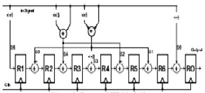
Fig.4 7-tap FIR FILTER
The analog input signal must be sampled first and digitized using an ADC (analog-to-digital converter). The resulting binary numbers, representing successive sampled values of the input signal, are transferred to the processor, which carries out numerical calculations on them. These calculations typically involve multiplying the input values by constants and adding the products together. If necessary, the results of these calculations, which now represent sampled values of the filtered signal, are output through a DAC (digital-to-analog converter) to convert the signal back to analog form. It is known that the multiplication operation takes more cycles than an adder or shift register operation. If the number of multiplications in the structure is more, then more time is needed to perform the filtering operation. Thus, the speed of operation will be affected. In our project adders and time-shifters, replace the multipliers, thereby increasing the speed of operation as compared to traditional filter structures in which multipliers were present. The multiplication is the basic operation in computation of output y (k). Considering the multiplication of two n-bit numbers, we have the product of 2n bits. This way of multiplication is implemented in project while multiplying the coefficients and the input samples.
The developed software was applied to several FIR filters and compared to Mat lab’s Filter Design & Analysis (FDA). The FDA toolbox includes a feature to generate optimized VHDL code from the generated coefficients and was used to compare to the developed software. These parameters enable the Mat lab FDA toolbox to optimize the generated VHDL description by taking into account the use of adders and shifts to make the multiplications. This aspect enables code optimization, increase of circuit performance and the use of adder trees in the filter architecture in a similar way as the proposed software. As can be observed, the
IJSER © 2012 http://www.ijser.org
The research paper published by IJSER journal is about Area Reduction and Doubling the Speed of FIR Filter using VHDL 4
ISSN 2229-5518
architectures generated by the proposed software have a lower number of adders/sub tractors for all the filters. This is due to the optimized architecture generated by our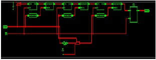
software that removes redundant adders and sub tractors more efficiently than the Mat lab FDA toolbox. It can be also observed that the filters generated by the proposed software present higher performance, when compared to the filters generated by Mat lab FDA toolbox. In fact, we have observed that the filter architectures generated by our software present a short critical path leading to higher frequency. Moreover, the VHDL code generated by FDA toolbox does not use good sub expression sharing algorithms for coefficient optimizations. We have also observed that the VHDL code generated using Mat lab FDA tool is much longer and complicated to understand than the proposed software. The Synthesized RTL Schematic and Behavioral simulation are shown in Fig. 5 and Fig. 6
Fig. 5 RTL Schematic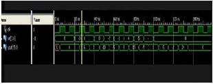
Fig. 6 Behavioral simulation
We have implemented a software tool that generates optimized VHDL descriptions for FIR filters. The developed software uses the algorithm of [1], which uses general coefficient representation in the optimization of the MCM problem. We presented results for several benchmark FIR filters. For these filters, our software is able to produce significantly better descriptions than commercial Matlab FDA tool. Moreover, the final synthesized filter circuits, targeting an FPGA have significant improvements. An important reduction in the
number of operators was achieved while, simultaneous, the maximum frequency of operation was increased. We got expressive results by reducing the number of
adders/subtracters up to 76% and increasing the operation frequency of some filters over 100%. As future developments of this work, we plan to integrate in our software a graphical interface to integrate the complete synthesis flow, from the filter specification to a synthesizable VHDL description. Synthesis results show that our tool is able to produce significantly better hardware than FDA toolbox, doubling the speed and reducing the silicon area by 75%.
Acknowledgements
This work was supported (in part) by the V.S.Lakshmi
Engineering College for women.
REFERENCES:
[1] http://www.dsptutor.freeuk.com/dfilt1.htm
[2] Carmelina Ruggiero, .SEGNALI BIOMEDICI 1. Laboratorio MedInfo
[3] .An Introduction to Digital Filters. by INTERSIL,
Application Note, January
1999
[4] Ifeachor E.C., Jervis B.W., .Digital Signal Processing.,2nd
Edition, Low Price
Edition 2007.
[5]http://www.Xilinx.com/bvdocs/whitepapers/wp116.pdf. [6] Jones D. L., .FIR Filter Structures., Version 1.2: Oct 10,
2004.
[7] Perry D., .VHDL., 3rd Edition, Tata Mc. Graw Hill
Publications, 2001.
[8] Bhaskar J., .VHDL primer. ,3rd Edition, Pearson
Education Asia Publications,2000
[9] Chen W. K., . Logic Design.,CRC Press, 2000.
[10] Wakerly J. F., .Digital Design & Practice.; Pearson
Education Asia 3rd edition
[11] .FPGA Architect - XilinxXC4000/Spartan. by ELANIX Inc.
[12] Burrus C S, .Digital Filters Structures described by
Distributed Arithmetic.,
IEEE Transactions on Circuits and Systems, vol. CAS-24,
page: 12, December
1977.
[13] http://en.wikipedia.org/wiki/floating_point
[14] Parhi K K., .A Systematic Approach for Design of
Digit-serial Signal
Processing Architectures., Circuits and Systems, 1991.
[15] Prokis J. G., Manolakis D. G., .Digital Signal Processing.
3rd Edition, PHI publication 2004.
IJSER © 2012 http://www.ijser.org
The research paper published by IJSER journal is about Area Reduction and Doubling the Speed of FIR Filter using VHDL 5
ISSN 2229-5518
[16] Antoniou A.,. Digital Filter., 3rd Edition, Tata Mc. Graw Hill publications, 2001.
[17] Mitra S. K., .Digital Signal Processing. 3rd Edition, Tata
Mc. Graw Hill Publications.
[18] Chapman S. J., . Matlab Programming for Engineers.,
3rd Edition, Thomson learning 2005.
[19] Lee H., Sobelman G E. .Performance Evaluation and
Optimal design for FPGAbased
Digit-serial DSP Functions.. Computers and Electrical
Engineering 29 ,2003
[20] Mirzaei S., Hosangadi A. and Kastner R. , .FPGA Implementation of High
Speed FIR Filters Using Add and Shift Method.,
International Conference on
Computer Design (ICCD ),pp 308-313, 2006
[21] Takahashi Y. and Yokoyama M., .New cost-effective
VLSI implementation of
multiplier less FIR filter using common subexpression
elimination., Proc. IEEE
Int. Symp. on Circuits and Systems (ISCAS 2005),
pp.845.848, May 2005.
[22] Rocha Ed., .Implementation trade-offs of digital FIR
filters,. Military Embeded
System, open system publishing,2007.
[23] Choi, Seak C. and Lee H., .A Partial Self-Reconfigurable
Adaptive FIR Filter
System,. signal processing systems,pp.204-209,2007.
Email id:mailme_brahmi@yahoo.com
IJSER © 2012 http://www.ijser.org