International Journal of Scientific & Engineering Research, Volume 4, Issue 4, April-2013 1163
ISSN 2229-5518
Arduino Based Mobility Cane
Jayant Sakhardande, Pratik Pattanayak, Mita Bhowmick
Abstract— Rehabilitating the handicapped by devising useful aid forms a part of portfolio for the biomedical engineers. Assistive technology helps in neutralizing the impairment. Recent advancements in embedded systems have opened up a vast area of research and development for affordable and portable assistive devices for the visually impaired. Right from the simple white cane up to the most advanced electronic stick, many designs have been proposed for the noble cause of aiding the visually impaired. But there have always been some ergonomic or financial constrains in the newer designs which have kept the white cane as the first choice for the maximum number of visually handicapped people. This project aims at the design and development of a detachable unit which is robust, low cost and user friendly, thus, trying to aggrandize the functionality of the existing white cane, to concede above-knee obstacle detection as well as below-knee detection. The designed mobility stick which is low cost, sturdy, and robust can be easily operated uses ultrasound sensors for detecting the obstructions before direct contact. It offers haptic feedback to the user in accordance with the position of the obstacle.
Index Terms— Arduino Board, Mobility Aid, Ultrasonic Sensor, Visually Impaired.
—————————— ——————————
1 INTRODUCTION
lobally, the number of people of all ages living with sight loss is estimated to be 285 million, of who 39 million are blind according to the World Health Organization
(WHO) [1]. Among many constraints faced by a blind person, the challenge of independent navigation and mobility is prom- inent. Generally visually impaired people rely on assistance of sighted persons to find their way or need an accompanying person to follow; at least during a training period. This means that the majority of visually impaired people cannot find their way autonomously in an unknown area. Generally visionless persons use a white cane or walking cane.
A white cane is a mechanical device dedicated to detect static obstacles on the ground, holes, uneven surfaces, steps and other hazards via simple tactile-force feedback. Its light weightiness and the capability to be folded into a small piece can be advantageous to carry around when not required. These simply designed canes are only capable of detecting below waistline obstacles like street curves, steps and stair- cases and simple guidance between distances. Although these canes are capable of detecting obstacles, receiving feed- back is very low. Therefore visually impaired individuals still find it difficult to navigate especially in unknown milieu.
A variety of high-tech devices, using different types of range finders are available in the market and have been wide- ly used too, but they are discarded on the basis of cost and other factors. Some of the old devices are Nottingham Obstacle Detector, (NOD) [2], Binaural Sonic Aid (Sonicguide) [3], Guide Cane [4], Mowat Sensor [4], C-5 Laser cane [5]. Advancement in
————————————————
Jayant Sakhardande is with Biomedical Department, Thadomal Shahani Engi- neering College, Bandra (W), Mumbai-400050, INDIA. E-mail: jayant_sakhardande@yahoo.com
Pratik Pattanayak is with the Deparment of Biomedical Engineering, Thadomal
Shahani Engineering College, Bandra (W), Mumbai-400050
Dr.Mita Bhowmick is Professor and Head, Department of Biomedical Engineer- ing Thadomal Shahani Engineering College, Bandra (W), Mumbai-400050, INDIA. E-mail: mitabhowmick@gmail.com
technology has resulted in developing the old devices into new ones with additional features.
(i) The K-Sonar is based on the use of ultrasound wherein the ultrasonic waves bounce off obstruction and send infor- mation about object and the location. The feedback is provided through sound signatures [6].
(ii) The Ultracane is employed with a sual range, narrow beam ultrasound system which helps in determining objects in the user path. The range data obtained from the sensor is de- livered to the user via two small button-shaped tactile vibra- tors mounted in the handle of the device [7].
(iii) The Palm Sonar is termed as a palm-attached electronic mobility aid, when it locates object in the path o fthe ultrasonic beam. The object information is conveyed through vibrator stimuli [8].
(iv) The Mini Guide is a device which is a hand held device used to determine an obstacle. Ultrasonic waves are used and echo signal helps in locating the obstacle. The obstacle infor- mation is provided to user with a change in the vibrator fre- quency. The faster the vibratoion rate the nearer the object. Moreover, it is also consists of an earphone socket which can be used to provide sound feedback [9].
The aspiration of the research work was to design and de- velop a device for sensing the surrounding environment using ultrasonic sensors and sending the feedback to the user of the position of the closest obstacle in sensor’s range wirelessly. This modifies the traditional cane as it is enhanced by furnish- ing information about the obstacles before direct contact, as the cane does not provide information beyond its immediate length. The obstacle detection signal is transmitted to the vi- brator. Four vibrators are used; the first two are for the ob- struction above knew and the third one is for pothole detec- tion or staircase detection, while fourth one is for water detec- tion, thus enhancing thue user to get more close to real envi-
IJSER © 2013 http://www.ijser.org
International Journal of Scientific & Engineering Research, Volume 4, Issue 4, April-2013 1164
ISSN 2229-5518
ronment [10].
2 SYSTEM DESIGN
The arduino based mobile stick makes the visually impaired
person informed about the obstructions beforehand. Such aid
gives user more knowledge about the environment and ena-
bles them to make decisions much more quickly, thus allow-
ing them to move around more confidently and effectively.
The cane may be used in the nearby environment may be in a
park, at work, at home, and while a long journey. The de-
signed assisted device helps a visionless person to anticipate
the surrounding using the sensor and vibrations.
The following block diagram describes the prototype model
of obstruction detector system. An Arduino is used as system
controller. The various components of the system are dis- cussed below.
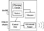
Fig.1 System block diagram of obstruction detector
A. Battery and ON/Off Switch
The system is powered from two Lithium-Ion rechargeable
batteries summing up to 7.4V. The regulated supply of 7V is
given to the Arduino Board through a toggle switch operated
by the user via protection circuitry. The ultrasound module is
supplied with 5V power. So a total of four LI-ion batteries are
required [11].
B. Charging Circuit and USB/AC Adapter
A battery charger is a device used to supply energy into a
secondary cell or rechargeable battery by forcing an electric
current through it. The charging protocol depends on the size
and type of the battery being charged. A battery charger can
be a simple Nokia charger or an AC adapter. USB slot is pro- vided in case of future programming of the device.
C. Ultrasound Sensor Module
Ultrasonic sensor was used, as, it is less affected by target
materials or by colour, it is capable of detecting objects within
a meter. These ultrasonic sensors are designed to resist exter-
nal disturbances such as vibration, infrared radiation, ambient
noise, and EMI radiation. The sensor used is a SRF-04 which is
equivalent to a Polaroid sensor. It requires a short trigger
pulse and it provides an echo pulse. Ultrasonic waves are
emitted from the module and bounce back when hits an ob-
jects and obstructions in the path of the user. The output of the
sensor provides change in voltage with respect to the distance of the obstacle.
D. Control Unit
The control sub-system consists of an Arduino Board hav-
ing an ATMEGA328P microcontroller merged in it [12]. Ar- duino is an open-source single board microcontroller, heir of the open-source Wiring platform, thus helping in designing electronics projects easily. The hardware consists of a simple open hardware design for the Arduino board with an Atmel AVR processor and on-board input/output support. The software consists of a standard programming language com- piler and the boot loader that runs on the board [13].The sen- sor output is provided to an Arduino which calculates the dis- tance based on the program. The obtained value is compared with the fixed value and a vibratory pattern for vibrators 1and
2 is generated according to the zone (Fig 2). The vibrator 3 continuously tracks the terrain and unevenness in the terrain (Fig. 3) turns the vibrator ON, thus a visionless person can walk prudent. It can be also used for staircase detection.
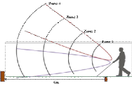
Fig.2 Angular coverage of the detection zone
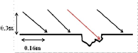
Fig.3 Pothole detection of the obstruction system. The black line shows a constant reading while the red line shows the fluctuation wherein the vibrator 3 would be turned on.
E. Vibrators
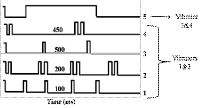
The system consists of four vibrators placed over the fore-
arm guard (Fig.5). The vibratory pattern (Fig.4) depicts, the
four patterns are for the vibrator 1 and 2 while the fifth pattern
is for vibrator 3. Vibratory patterns (Fig.3) are generated by
manipulating the duration, thus changing the interval be-
tween successive vibration pulses. As a result by recognizing the vibratory pattern the user can infer the obstacle distance. When the obstacle is in Zone 1 (Fig.2) then vibratory pattern 1 (Fig.3) is experienced. When the terrain surface is uneven then
the vibrator 3 provides a long pulse until the terrain surface is even. The fourth vibrator portrays presence of water and thus helping user to navigate safely.
IJSER © 2013 http://www.ijser.org
International Journal of Scientific & Engineering Research, Volume 4, Issue 4, April-2013 1165
ISSN 2229-5518
Fig.4 Pictorial representation of vibratory patterns
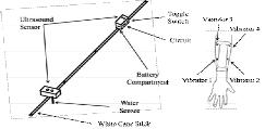
Fig.5 Prototype model of the obstruction detection system
The working of the designed cane is described in the fol- lowing sections.
The two detachable units which have been developed can be mounted on the top fold of the white cane. The upper de- tachable unit employs directional ultrasound based ranging to detect obstacles in front or above knee height within range of
3m. The user acquires distance information through haptic feedback. The device vibrates in distinct patterns that vary with changing obstacle distance [14].
The lower detachable unit is used for pothole detection or staircase detection. The ultrasound sensor receives a constant reading while the terrain is even, in the case of unevenness, the reading changes thus activating the vibrator and making the user walk gingerly. The detachable unit also comprise of a water sensor, which would detect presence of water and acti- vate vibrator 4.
The system has been premeditated as an independent de- tachable unit so that the existing white cane does not have to be re-modelled. An attachment mechanism has been devel- oped so that the user can attach the device on the cane without sighted assistance. The unit can also be used as a general pur- pose distenace estimation device. The module runs on stand- ard Li-ion rechargeable battery. For charging, the user con- nects an aAC or USB adapter (similar to charging a cell phone). This eliminates the inconvenience of opening the bat- tery pack to replace batteries.
3 RESULTS
A distance calculated experiment was performed by placing an obstacle at a meticulous distance and calibrating. It con- cluded a faithful output uptil 3m. As a result the range was divided into four zones, and, each zone was specified a partic- ular vibratory pattern.
The experiments regarding the current consumption of vi- brator were performed. The Arduino drives the vibration mo- tor by supplying a known amount of current for different pat- terns. Since pattern 1 corresponds to the obstacle being closest, the frequency of vibration is the highest. Consequently, max- imum current is required for pattern 1. This current has a spe-
pattern are recorded by connecting a digital multimeter into the circuit. The evaluation of the experiment is shown in the following figure.
Table 1
Current consumption of the vibrator for various vibratory patterns of virators 1& 2
The other experiment includes the calibration of the ultra- sound sensor. The table shows calculated and measured val- ues of analog voltage produced at the ultrasonic sensor input.
Table 2
Performance analysis of ultrasonic sensor in obstacle detection
There is a slight difference amongst the values measured and observed as per the table. It shows that the device was not capable of showing exact values and ended in errors. The graph of the readings is plotted.
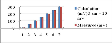
Fig.6 Difference between the calculation value and the measured value in the analysis of ultrasonic range finder
The next statistics include the calibration of pothole detection. When the unevenness in the surface was noted then the out- put voltage changed. The sensor is placed at 0.3m vertically from ground and 0.16m horizontally. The pothole was 0.5m deep. Whenever the surface was even the measured voltage value was recorded, as soon as the device detected uneven- ness in the surface, the change in the voltage value triggered vibrator 3.
Table 3
Experimental analysis of ultrasonic sensor for pothole detection

cific rise and fall time depending upon the pattern of vibration given to the user i.e. it would not remain constant for a pat- tern. The current supplied to the vibrator for each delivered
IJSER © 2013
Calcula- tion(mV)3cm
=10mV
Meas- ured(mV)
Error:(cal- meas)/cal
http://www.ijser.Norog rmal Values(Sensor
level 0.3m from ground) Pothole Values (0.5m deep pothole)
0.33 V 0.295V 0.106
0.495V 0.488V 0.014
International Journal of Scientific & Engineering Research, Volume 4, Issue 4, April-2013 1166
ISSN 2229-5518
4 DISCUSSION
The discussion section is divided into three parts, the detailed analysis of the results, followed by comparison of other avail- able devices over the assembled one, and the patient training procedure. From the above experiments, it is clear that the device provides some errors due to external factors. There is a scope to improve the accuracy. Moreover the current con- sumptions value helps in determining the number of Li-ion batteries and the working time of the device. In water detec- tion system a 5V output is provided which is given to the con- trol unit for processing and thus vibrator 4 is turned on. A table below portrays the functional limitation of various available devices in the market and the approximate cost of
those devices.
Table 4
Limitations of existing Ultrasound based Devices
Device | Limitations | Price (INR) Approx |
K-Sonar | -Auditory output can interfere with envi- ronmental sounds. -Additional training is required. | 31,500 |
Ultracane | -System is integrated with a carbon graph- ite cane. -Vibration is provided through two small buttons. -Attaching to existing cane is impossible. | 44,000 |
Palm So- nar | -The device cannot be mounted on the cane. -The device is held in one hand and the stick in other hand. | 24,000 |
Mini Guide | -Prone to breakage because of hard plastic case. -Training is necessary. -Device cannot be mounted on the cane. | 25,000 |
The Arduino based stick tries to overcome most of the limi- tations. The vibrator false triggering is removed through pro- gramming. Moreover this device can be attached to existing cane. This device covers the above knee, below knee, potholes and water detection system which is superior functionality over available devices. The system cost up to 5,000 INR which is much lesser than the available devices.
The limitation of the Arduino based stick could be that the obstacle towards extreme right and left may not be detected, so pivoting a servo motor rotating through an angle of 40 de- grees to 135 degrees can provide a sector scan and thus can detect moving obstacles within this beam range more effec- tively. A buzzer can be added so the buzzer will activate at a specific duration. Hot object Detector can also be incorporated for the detection of hot obstacles.
The training procedure initially starts with basic operating instruction further by basic training concepts, then exercise using Arduino stick. Some floor exercise followed by the exer- cises in landmark recognition and spatial navigation.
5 CONCLUSION
A low cost, sturdy and robust arduino based Mobile stick was designed and developed for Visually Impaired People with the help of ultrasound sensor. The designed prototype can be made more equipped by making the sensor rotate to make it a perfect device for a visually impaired person. Future work will concentrate on improving the performance of the proto- type model.
The system was developed in close association with poten- tial users. Feedback was taken during the problem formula- tion, concept design and prototype evaluation stages which were critical for achieving our objectives. Initial experiments with the target group demonstrated their utility in real life scenarios Users were able to detect raised obstacles like side of a truck, horizontal bar and the edge of a table much before coming in contact with them.
References
[1] Global data on blindness. Facts sheet, Key Facts of the World Health
Organization; June 2012.
[2] Dodds, A. G., and J.D. Armstrong, and C.A. Shingledecker. “The Nottingham Obstacle Detector: Development and Evaluation.” Jour- nal of Visual Impairment and Blindness, v75 n5 p203- 09, May 1981.
[3] Allan Dodds, “Mobility Training for Visually Handicapped People: A Person-Centred Approach.”, pp 33-35, Croom Helm limited, 1988.
[4] Borenstein, J., and I. Ulrich. “The Guide Cane — a Computerized Travel Aid for the Active Guidance of Blind Pedestrians.” Interna- tional Conference on Robotics and Automation, Albuquerque, NM, pp.1283-1288, Apr. 21-27, 1997.
[5] Benjamin, J. M., “The New C-5 Laser Cane for the Blind." Carnahan
Conference on Electronic Prosthetics, Univ. Kentucky Eng Experiment
Station, pp. 104-106, 1973.
[6] Bay Advanced Technologies Ltd, (2006), “The Bat K-Sonar”, http://www.batforblind.co.nz/, November 2012.
[7] Ultracane, “Ultracane”, http://www.ultracane.com/, November 2012. [8] Palmsonar, (2012), “Palmsonar and Palmtip”,
http://www.palmsonar.com/, November 2012.
[9] “The Miniguide Ultrasonic Mobility Aid”, http://www.gdp- research.com.au/minig_1.htm, November 2012.
[10] Anoosh G, Raghunandan Srinivasan, Sundar Aditya, Dr. Nagendra
Krishnapura, 2010, “Pothole Detection”, TI Analog design contest
2009,http://www.ti.com/ww/in/downloads/2009/ti_ads_iit_madras2. pdf, June 2012.
[11] Wikipedia the free encyclopaedia, 2010, Lithium-ion Battery, http://en.wikipedia.org/wiki/Lithium-ion_battery, March 2012.
[12] Arduino, (2004), “Arduino- An Introduction”, http://arduino.cc/en/ Dec
2011.
[13] Wikipedia the free encyclopaedia, 2010, “Arduino”, http://en.wikipedia.org/wiki/Arduino, March 2012.
[14] Peter H. Aigrer and Brenan J.McCarragher, “Shared Control Frame- work: Applied to a Robotic Aid for the Blind”, IEEE Journal Control Systems, Vol.19, No.2, pp40-46, April 1999.
IJSER © 2013 http://www.ijser.org