International Journal of Scientific & Engineering Research, Volume 5, Issue 12, December-2014 79
ISSN 2229-5518
Anfis with Cauchy membership function for robotic arm
NaserAlanabi1 , Dr. Jyoti Shrivastava2
1 Research Scholar, 2 Senior Assistant Professor
1,2 Department of Electrical and Electronic Engineering , College of Engineering and Technology, SHIATS, Allahabad, India.
Email :1nnassa1968@gmail.com, 2jyotishri72@rediffmail.com
Abstract-An adaptive fuzzy gain scheduling scheme for robotic arm has been proposed. This paper focus on adaptive fuzzy based tracking and gain controller algorithm for obtaining the joints position relative to the desired trajectory, which drives static and different time variations on the environmental changes. We able to estimate them at any point of time, when t >0 or alternatively, starting from the fuzzy initial states, Fuzzy initial states along with system dynamic equations provide us particular fuzzy differential equations (FDEs), referred as fuzzy Cauchy problem, we construct the fuzzy Cauchy problems during the initial time, we introduce two different ways, first we apply the non-fuzzy differential equations with initial conditions of data based. And the second, we apply with anfis with Cauchy membership function for robotic arm to apply with two angles. The proposed adaptive fuzzy based tracking and gain controller algorithm requires much less training patterns than a neural net based adaptive scheme does and hence avoiding excessive training time. Results of simulation show that the proposed adaptive fuzzy controller offers better performance than fixed gain controllers at different operating conditions.
Index terms-Fuzzy logic, Cauchy Membership Function, ANFIS, Robotic arm.
1 INTRODUCTION
————————————————————
Lee [5]. Thesteady adaptive fuzzy-based chasing control for
roboticarmbyconstraint uncertainties and
In the brainy control of a robotic arm,
movementschedulingplays a vital role and also akey task.
The greatest interesting task is the difficult of picking stability through the dynamic equations of nonlinear to undefinedsituation. To perform these tasks, the solicitations of artificial intelligence like fuzzy logic and neural networks in designing and control are considerably developing particularly in latest years. For this, manyresearchers introduced numerous methodologies used genetic algorithms or fuzzy logic [9, 10, 12, and 13]. In order to permit for fuzziness and uncertainties of path statistics, path state of affairs can be demonstrated using fuzzy linguistic variables.Robotic arm is also established using new simple and overalloutlinetechniques for Robotic control[7]. The basis of malfunctioning of the Robotic arm is the obstacles.To overcome this issue, numerousdeterminations have been doneby providing effective arm movement routes for escapinghindrances. When assign this as probability, thisdriveslaterallywith the real time procedure and their control for improved performance. The design and methods for probabilistic self- localization for Robotic arm was established by Olson C.F. et al. [6]. To provide path optimization of multiple manipulators, Garget. al. effectivelyapplied torque reduction for path optimization of multiple manipulators[8].To advance accurate mathematic model, Zhang MingLu and Jiao Xinjing applied the classical control theory which produced the substantial results [5].To estimate the unfamiliar robotic dynamics, Fuzzy logic system is presented by using adaptive algorithm. Fuzzy system to robot course-plotting is introduced by Edward T.
exteriordisruption was developed by H. F. Ho et al. [11].Ahamed W has applied sustainable attention to the intellectual control techniquedepends on the design of structureperformance such as the ant colony algorithm, fuzzy control method[14]. Neverthelessthese methods has an essential to improve their performance. Particularly, the pure performance model is discussed through the fuzzy logic and the unique mathematical design is unnoticed and the offline phase fuzzy control demonstrating scheme is simplydebated. In order to make the picking arm apperceive accurately complex environmental condition, to regulate their speed and reach smoothly the target position.
The electrical portions of robot manipulators are used to run the regulators, actuators, which also has the subsequent sub portions: DC/stepper/servo motors or hydraulic/pneumatic cylinders, power amplifier, power supply,and transmission part [1, 2&4]. To regulate the timing between the sub portions of robotic arm to spread the toproute,Control part is used.The greatest task in control algorithms is a linear comportment controller project for nonlinear systems. Linear PID controllers are used in robot manipulators. In this, when we go for designing part, this robotic manipulator is very hard since this system is barely nonlinear and indeterminate.To mitigate aforementioned issues, the nonlinear robust controller is used to control the system of nonlinear. In which, the Computed torque controller is a powerful nonlinear controller. The concept behind this is feedback linearization and calculation of the compulsory arm torques by the control law of nonlinear feedback. This controller performs very healthy, when altogetherthe sphysicaland
IJSER © 2014 http://www.ijser.org
International Journal of Scientific & Engineering Research, Volume 5, Issue 12, December-2014 80
ISSN 2229-5518
the dynamic constraints are identified. It has the disadvantage i.e dissimilarity in dynamic constraints.
In this paper, we have used the fuzzy tracking controller to get the wanted joints tracking route. By this, we can maintain the performance of the robotic arm by the parameters like taking coordination skill and driving velocity and angle velocity on the circumstances of alteringsituation. To overcome the aforementioned issues like nonlinear and uncertainties,we have used the nonlinear robust controller which is used to regulatethe roboticarm. Here the nonlinear controller is Computed torque controller. And we have used fuzzy logic theory tomitigate the uncertainties difficult. In this investigation,we have applied PD fuzzy controller to adjust the coefficients of CTC.
2 RELATED WORK
2.1.Robotic Systems
The robotic structures are brandedthrough their degree-of
freedom. A very simple robotic system which has twoDOF while a complex robotic system which has moreDOF. The robotic arm movement is stimulatedbythe constraints of friction, settling time and joint motion.The parameter of friction need to be careful with respect to robotic arm movement. The most significant feature in the circumstance of any real time designs is settling time. The transient response is mentioned by the settling time. High-speed robots have the smallest settling time. By this, this provides less physical vibrations in the motion of robotic arm. The joint motion is based on the angular motion of the joint. The power requirement is regulated by the Joint movement. The theoretical angular movement is defined by the actual angular arm motion which is delivered by the controller minus the movement lost due to friction.
2.2 Dynamic Formulation of 2-DOF Robot Manipulator
To define the performance of robotic manipulator such as nonlinear or linear dynamic behavior, Dynamic modeling of robot manipulators is used.The link of parameters among accelerations to force/torque or current/voltage, joint movement and velocity is defined by the dynamic design of Robot manipulator and the specific dynamic effects of inertia, coriolios, centrifugal, and the other parameters to the performance of system is also termed by the dynamic design of Robot manipulator. The subsequent equation is the equivalence of an n-DOF robot manipulator equation[2, 3]:
M(q) + N (q,q') = τ
vector of nonlinearity term. This dynamic equation can also be inscribed in a succeeding form [20-25]:
τ = M(q)q' + B(q) [q' q'] + C (q) [q']2 + G(q)
(2)
Where C (q) is the matrix of centrifugal torques in manipulator position, B (q) is the matrix of coriolios torques in manipulator position, and G (q) is the vector of gravity force in manipulator position. This is represented as a decoupled designbythe humble second order linear differential dynamics. Thus, the angular acceleration is originate as future [4]
q'= M-1(q);{τ - N(q,q')|
(3)
By the control fact of opinion, this method is very
pretty.
2.3Representation of Picking Robot Arm Trajectory
Tracking
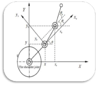
The recent posture of taking robotic arm is shown as Fig.1. This is denoted as (x,y,θ), the expectation posture denoted as (x,y,θ),additionally the input regulatory point of picking and controlling robotic arm is represented as P,(v,w,), route error of picking and controlling robotic arm is described as next in terms of coordinates,
[𝑥𝑒] [cos θ sin θ 0] [𝑥𝑟 − 𝑥]
[𝑦𝑒] [−𝑠𝑖𝑛θ 𝑐𝑜𝑠θ 0] [𝑦𝑒 − 𝑦](4)
[θ𝑒] [0 0 1] [θ𝑟 − θ]
The differential posture error equations is representedby
the succeeding
{xe = w ye –v + vr cos θe
{ye = -w xe + vr sin θe
{θe = wr -w
(5)
(1)
Where τ is the actuation torque, M (q) is the symmetric
and positive described inertia matrix, (N (q, q’) ̇) is the
Figure.1 Diagram of Pose Error for Picking-arm in the
Coordinate
IJSER © 2014 http://www.ijser.org
International Journal of Scientific & Engineering Research, Volume 5, Issue 12, December-2014 81
ISSN 2229-5518
To discover the prerequisite of the limited joint angular velocity w and joint input velocity v, the scheme (x`e ,y`e ,Ѳe )T should be restricted on the condition of control input and encounterby the state of
any error for the determination of looking for control degree. Initially based on the preferred path curvature, adjustthe fuzzy control variable of the joint velocity, then apposed ye and Ѳe control input to getthe fuzzy chasing control variable of joint angular velocity.
2.4The Picking Arm Fuzzy Control Strategy
The dynamic features of the picking and controlling robotic arm route planning is extremely nonlinear motion with the speed of 0.5 to 15 km/h, which features difficultlink of time domain and the distributed system constraints. So, in order to overcome the stability control problem, it is vital to create thewhole mathematical design to label the origin of control motivatingnecessities. By using fuzzy logic, it can improve the user practiceperformance to mimicthe human dynamicexpectation and reaction behavior without using not much mathematical expression andcreatethe steady fuzzy choice and performthe determined discrimination. The fuzzy controller based on the principle of taking robotic arm is shown in Figure.2.The main assemblycomprisesthe exactfuzzification, fuzzy judgment, fuzzy approach and fuzzy control instructions.
relationship diagram are shown in Figure.3 and Figure.4, so applying the fuzzy chasing algorithm is the trajectory tracking control goal andcreate it charming and firm run in order todetain its waving.
Err Cha nge Rati
Fuz zific atio
Pic kin g
Fuzz y Con trol
Fuz zy Dec
Joi nt
Fuz zy Str ate
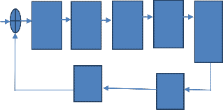
Figure.2 The Fuzzy Control Principle of Picking-arm
The Joint velocity error and joint Velocity Error in Angularare the input language variables.Todiminish the overshoot and decline the influence, these input language variables can promisethe system on start-up and acceleration trembling of taking robotic arm.
2.5Non- Fuzzy Relation between Posture and the
Desired Trajectory
This section explains the control characteristic of non- fuzzy associationamongthe posture and the wantedroutewith the real picking power transmission and the attainedpreferredthrough the literature review.The arm joints initiate quality center angle and driven time
IJSER © 2014 http://www.ijser.org
International Journal of Scientific & Engineering Research, Volume 5, Issue 12, December-2014 82
ISSN 2229-5518
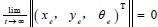
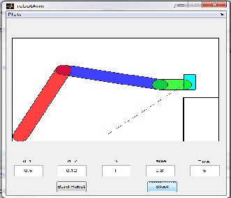
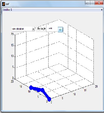
Figure a,b,c states theat Driven State Postion of the
Robotic Arm Movement
2.6Picking Arm Fuzzy Controller
The two input variables of the angle error TGand Velocity Error in AngularTGC and an output variable u and the 56 rules are present in the fuzzy controller of picking and controlling robotic arm .
(1). The angle error TG: consider the fixed error Tgand
feedback error Tfare linguistic variables TG, the membership function formis shown in Figure.5, the center point of TG triangular formfluctuationsconsistently within [-0.03:0.01:0.03].
TG= Tg- Tf (6)
Figure.5 TG Membership Function
(2). The Velocity Error in AngularTGC:observed as angular velocity variance error in separate time, the joint angle speed error membership shown as Figure.6, the representation of the linguistic variables is given below, TGC=TG*t*T-TG(t-1)*T)/Δt. (7)
Where, differential time is t-kT(k=0,1,2,…n),T is the
period of sampling, 7 triangular membership occupations are described as Figure.6, the membership midpoint variable alteredin [-0.5:0.2:0.5].
Figure.6 Membership Function of TGC
will be used to do the command. If the output variable is unstable, the improvement of the anti-fluttering requires the steadyingaction.So, the fuzzy based rule strategy is core design of picking arm.
Figure.7 Joint Output Control Linguistic Variable U
3PROPOSED WORK
This section explains the algorithm of fuzzy control for picking and controlling robotic arm and the algorithm of fuzzy tracking and the fuzzy gain scheduling controller using Computed torque controller.
3.1Adaptive Fuzzy Control Algorithm of Picking & Controlling Robot Arm
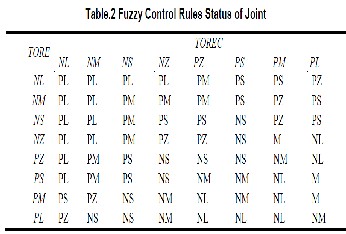
The fuzzy control algorithm shadowed the "If TG and TGC then U". The algorithm of Fuzzy control for picking and controlling robotic arm using TG, TGC,U and 56 inference language rules is proposed as R following
(1)If TG=NL and TGC=NL then U =PL
(2)or If TG=NL and TGC=NM then U =PL
(3)… … … …
(55)or If TG=PM and TGC=PL then U =NL
(56)or If TG=PL and TGC=PL then U=NL
The human strategy is reproduced by theoverhead
34 fuzzy control rules. The variables of Linguistic are described in the sets of fuzzy. Based on the knowledge of fastremoval rules, the fuzzy algorithm is attained.The control rules of fuzzy for picking robot arm shown as Table.2
(3) Output Variables in Joint U: Joint triangle
figure’smidpoint lies respectively -0.2, -0.12, -0.05, 0, 0.05,
0.13, 0.2, thephysical features of research and sensor are
decided by the variable form. The joint servo motor in 2ms
IJSER © 2014 http://www.ijser.org
International Journal of Scientific & Engineering Research, Volume 5, Issue 12, December-2014 83
ISSN 2229-5518
When the rules of fuzzy R is increased, TGand TGC can be achieved consequently and the fuzzy controller output attainedU1=TG1× TGC1, thesuperficialvision for 34 fuzzy rules can be exposed as succeeding.
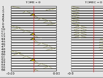
Figure.8the Surface Views of 56 Fuzzy Rules
3.2Adaptive Fuzzy tracking Algorithm Design
To achieve ourproposedtracking algorithm picking and controlling robotic arm in different torque and force with the help of adaptive fuzzy rules and base rules, we adopt the two order curve tracking method.This is observed the adjacent distance point from the picking box as the desired starting point. The preferred track in sector-by-sector and two times curve solution is estimated. And our designtrack
target point which computed in the coordinate system and apply two order curve to attach the point of the target and the origin in place of the expectations succeedingroute. To define the angular acceleration w and angular velocity of arm joint v,this tracking algorithm is used in the trajectory design.
Y = Ax2 , A = Ye / X2 e (8)
{ v = sqrt (x2 (1 + 4 A2 x2))
{w = 2A x3 / v (9)
estimate the solution can be increased as following
{vn ≅Kn
{wn = 2 An Kn (10)
By computing vn and wn,, we may choice the parameter of control cycle and speed control aand then, in order to reduce the deviation, the picking and controlling robotic arm joint angular velocity vnand acceleration wn attuned suitably tand to attain route tracking right deviation,take the shortest distance goal path from the taking apple slowly.
3.3Design Computed Torque Controller

The great nonlinear methodproposed to control the robot manipulator is the torque controller. The concept behind this is feedback linearization and calculation of the compulsory arm torques by the control law of nonlinear feedback. This controller performs very healthy, when altogether the physical and the dynamic constraints are identified. When we go with practical session, the most of physical model parameters are unknown or time variant.Consequently, to remunerate the equation of dynamic robotic manipulator, CTC need to be mixed with themethods of other.The computed torque controller for tracking reaction is proposed by Vivas and Mosquerain indeterminate atmosphere. When we compare this with the predictive approach, predictive plan gives healthier result than the overheadinvestigation. If an alternative linear
state-space equation in terms of =Ax+BUdescribed as following
0 1 0
�x + �
�N (12)
picking trajectory and two order curve appropriately. Even
though this is moderately common to the tracking
trackwiththe flexibility, tracking accuracy,andvirtue of
good stability.For tracking rectification, it is appropriate. The Eq. 8. Which explains algorithm principle. We have to reflectthat we optimalthe target picking position point P(v,w) then the deviation vector point (x,y, ) for the picking
x' = �0 0 1
where N = B (q) [q' q'] + C (q) (q')2 + G(q) and this is
recognized as the Brunousky canonical form. By equation (10) and (11) the Bruno sky canonical procedure can be inscribed in the form of the state x = [eTeT]Tas [1]:
IJSER © 2014 http://www.ijser.org
International Journal of Scientific & Engineering Research, Volume 5, Issue 12, December-2014 84
ISSN 2229-5518
0 1
d/dt[e e'] = �
� � 𝑒 � + �0� N (13)
succeedingdescription shows the fuzzy rule base of
0 0 𝑒′ 1
Mamdani and Sugeno methods.
This is a control law of nonlinear feedback
whichassurancesthe route of the tracking of robotic manipulator. When we choose the proportional-plus- derivative feedback for N(t), it outcomes in terms of the PD-CTC ;
τ = M(q) (q'd + Kv e' + Kp e) + N(q,q') (14)
The conjunction of the tracking error to zero is
assured bythe linear system theory. Where KpandKvare the
gains of controller. The result schemes is shown in Figure 9.
It has two feedback loops, namely, inner loop and outer loop. In this, an inner loop is a remunerateloop and an outer loop is the loop of tracking error.
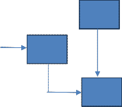
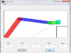
Fig. 10.Fuzzy Controller
Fuzzy
Rule
Fuzzifi er
Defuz zifier
Fuzzy Intera
Fig.11. Block Diagram of Fuzzy Controller
Fig. 9. Design Computed Torque Controller
3.4Fuzzy Logic Methodology
The fuzzy logic controller has played vital rule to model the nonlinear controller for nonlinear and uncertain designsbased on basis of fuzzy logic methodology [21-25]. The fuzzy control which has broad application area and simple controller comprises Input fuzzification, Fuzzy rule base, Inference engine and Output defuzzification. The block diagram of fuzzy controller is shown in Figure 10. The block diagram of controller to regulatethe 2 DOF robot manipulator is shown in Figure 11.
To transmit the rule base in the set of fuzzy, the
fuzzy inference engine proposals a mechanism. It is separated into two most significant methods i.e. Mamdani and Sugeno methods. Mamdaniwho considered one of the first fuzzy controllers to regulatethe system engine. This design is allocated into four ladders: fuzzification, rule evaluation, aggregation of the rule outputs and defuzzification. MichioSugenowho practice a singleton as a membership purpose of the rule resultantportion. The

If x is A and y is B then z is C ‘mamdani’ (15)
The Figure 11 shows the membership functions and philological variable.The rule calculationconcentrates on fuzzy rule in the forerunner of the rules of fuzzy. To compute the output of fuzzy set, the aggregation is used.
Wherer is the number of fuzzy rules triggered by
xkandy k and,is the fuzzy amplification of i-th rule. The final and last step in the fuzzy inference system is the Defuzzification.To convert fuzzy set to crisp set, it is applied. Sothe input of defuzzification is the output of aggregate and the output of defuzzification is a crisp number. The common defuzzification methods are Centre of gravity method and Centre of area method. The following equation is used in COG technique to compute the defuzzification,
Where COG (xk, yk) and (xk, yk) demonstrates the
defuzzification output of crisp value, Ui£U is the output of the fuzzy set in terms of discrete element, ( .(xk, yk,Ui) ) is the fuzzy set membership function, and r is the number of fuzzy rules.
3.5Discussions over proposed approach
The proposed method performs very well and gives improved control than nonlinear PID control, when we have all essential information about the constraints of
IJSER © 2014 http://www.ijser.org
International Journal of Scientific & Engineering Research, Volume 5, Issue 12, December-2014 85
ISSN 2229-5518
robotic manipulator andthe nonlinear dynamic formulation of system. This is very tough in reality while the dynamics of the robotic arm can alterthroughout the process which can disturb the outcome of the control. Here we can reduce the outcome of CTC because of the dynamic design. And fuzzy system is applied to online alteration of the CTC parameters to avoid this state. By this, we can attain the wanted settling time and very minor steady state tracking errors. Constructed on fuzzy logic procedure
4SIMULATION RESULTS
f(x) = Ufuzzy = ∑𝑀
θ𝑇 τ(𝑥) (20)
where is the adjustable parameter and (τ(x) ) is defined by
τ(x) = ∑ µ(𝑥𝑖)𝑥𝑖

𝑖 µ(𝑥𝑖 )
Where µ(xi) is the membership function.
(21)
This procedure has two core portions; first one is the computed torque controller and the second one is fuzzy tuning controller. Centered on this procedure;
τ = M (q) (qd+ Kv x Ufuzzy (e') + Kp x Ufuzzy( e ) ) + N (q,q') (22)
If the Lyapunov function in this techniquedecribed as follows;

µ(𝑥𝑖)𝑥𝑖
V = (1/2) M(q') x qT x q') + eTKp e) + 1/2 (23)
µ(𝑥𝑖 )
And the distinguish to attain
Consequently the skew symmetry of the initial term is given by;
V = -qTKq' - ∑𝑀
1 Φ𝑇. Φ𝑗
(24)

𝐽=1 𝑌𝑗
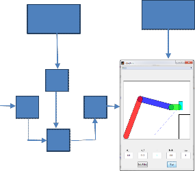
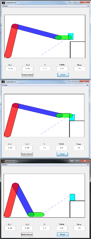
The projectedtechnique is shown in Figure 6.
Data
Base
F
F D
F
Rule
Base
Fig. Adaptive Fuzzy Gain scheduling Controller
IJSER © 2014 http://www.ijser.org
International Journal of Scientific & Engineering Research, Volume 5, Issue 12, December-2014 86
ISSN 2229-5518

5CONCLUSION
We apply with anfis with Cauchy membership function for robotic arm to apply with two angles. The proposed adaptive fuzzy based tracking and gain controller algorithm requires much less training patterns than a neural net based adaptive scheme does and hence avoiding excessive training time. Results of simulation show that the proposed adaptive fuzzy controller offers better performance than fixed gain controllers at different operating conditions.
5.1 Acknowledgments
REFERENCES
[1] M. Bazregar, FarzinPiltan, A. Nabaee and M.M. Ebrahimi, “Parallel Soft Computing Control Optimization Algorithm for Uncertainty Dynamic Systems”, International Journal of Advanced Science and Technology,
51, 2013
[2] MojtabaYaghoot, FarzinPiltan, MeysamEsmaeili,
Mohammad Ali Tayebi, MahsaPiltan,"Design Intelligent Robust Model-base Sliding Guidance Controller for Spherical Motor", IJMECS, vol.6, no.3, pp.61-72, 2014.DOI:
10.5815/ijmecs.2014.03.08
[3] M. Mucienteset.el. , “Design of a fuzzy controller in
mobile robotics using genetic algorithms”, Elsevier Applied
Soft Computing, Vol. 7, and No. 2, 540-546 (2007).
[4] Ho H. F. at. el., “Robust fuzzy tracking control for
robotic manipulators”, Simulation Modelling Practice and
Theory, Vol. 15, Issue 7, 801-816 (2007).
[5] Nguyen. V. B. and Morris A. S., “Genetic Algorithm Tuned Fuzzy Logic Controller for a Robot Arm with Two- link Flexibility and Twojoint Elasticity”, Springer J Intell Robot Syst, Vol. 49, 3–18(2007).
[6]FarzinPiltan, Mohammad R. Rashidian, Mohammad Shamsodini and SadeqAllahdadi, Effect of Rule Base on the Fuzzy-Based Tuning Fuzzy Sliding Mode Controller: Applied to 2nd Order Nonlinear System”, International Journal of Advanced Science and Technology, 46:39-70,
2012
[7] W. Ahamed and C. Kambhampati, “Stable quantum
filters with scattering phenomena”, International Journal of
Automation and Computing, vol. 5, no. 2, (2008), pp. 132-
137.
[8] FarzinPiltan, Mohammad H. Yarmahmoudi,
Mohammad Shamsodini, EbrahimMazlomian, Ali
Hosainpour, ”PUMA-560 Robot Manipulator Position Computed Torque Control Methods Using MATLAB/SIMULINK and Their Integration into Graduate Nonlinear Control and MATLAB Courses”, International Journal of Robotics and Automation, 3(3): 167-191, 2012.
[9] FarzinPiltan, Mehdi Eram, Mohammad Taghavi, Omid Reza Sadrnia, Mahdi Jafari,"Nonlinear Fuzzy Model-base Technique to Compensate Highly Nonlinear Continuum Robot Manipulator", IJISA, vol.5, no.12, pp.135-148, 2013. DOI: 10.5815/ijisa.2013.12.12
[10] [19] S. Heidari, FarzinPiltan, M. Shamsodini, K. Heidari and S. Zahmatkesh, “Design New Nonlinear Controller with Parallel Fuzzy Inference System Compensator to Control of Continuum Robot Manipulator”, International Journal of Control and Automation, 6(4), 2013.
[11] Mahdi Mirshekaran, FarzinPiltan,ZahraEsmaeili, TannazKhajeaian, MeysamKazeminasab,"Design Sliding Mode Modified Fuzzy Linear Controller with Application to Flexible Robot Manipulator", IJMECS, vol.5, no.10, pp.53-
63, 2013.DOI: 10.5815/ijmecs.2013.10.07.
[12] Ali Barzegar, FarzinPiltan, Mahmood Vosoogh, Abdol Majid Mirshekaran, AlirezaSiahbazi,"Design Serial Intelligent Modified Feedback Linearization like Controller with Application to Spherical Motor", IJITCS, vol.6, no.5, pp. 72-83, 2014. DOI: 10.5815/ijitcs.2014.05.10.
[13] AzitaYazdanpanah, FarzinPiltan, Ali Roshanzamir, MarjanMirshekari, NargesGholamimozafari,"Design PID Baseline Fuzzy Tuning Proportional- Derivative Coefficient Nonlinear Controller with Application to Continuum Robot", IJISA, vol.6, no.5, pp.90-100, 2014. DOI:
10.5815/ijisa.2014.05.10.
[14] MeysamKazeminasab, FarzinPiltan, Zahra Esmaeili,
Mahdi Mirshekaran, AlirezaSalehi ,"Design Parallel Fuzzy Partly Inverse Dynamic Method plus Gravity Control for Highly NonlinearContinuum Robot", IJISA, vol.6, no.1, pp.112-123, 2014. DOI: 10.5815/ijisa.2014.01.12.
[15] FarzinMatin, FarzinPiltan, Hamid Cheraghi,
NasimSobhani, Maryam Rahmani,"Design Intelligent PID like Fuzzy Sliding Mode Controller for Spherical Motor", IJIEEB, vol.6, no.2, pp.53-63, 2014. DOI:
10.5815/ijieeb.2014.02.07.
IJSER © 2014 http://www.ijser.org
International Journal of Scientific & Engineering Research, Volume 5, Issue 12, December-2014 87
ISSN 2229-5518
IJSER © 2014 http://www.ijser.org