International Journal of Scientific & Engineering Research Volume 2, Issue 6, June-2011 1
ISSN 2229-5518
Analysis of Optical Wireless Communication for Underwater Wireless Communication
P.Vijaya Kumar, S.S.K.Praneeth, Romarsha.B.Narender
Abstract- Recently, the importance of underwater wireless optical communication has been grown for applications of underwater observation and sea monitoring systems. This communication technology is expected to play a prominent role in investigating climate changes, prediction of natural disasters, discovery of natural resources, marine biology in lake, sea, and ocean environment. Though acoustic modems have long been the default wireless communication method for under water applications due to their long range, the need for high speed communication has prompted the exploration of non-acoustic methods that `have previously been overlooked due to their distance limitations. Optical wireless communication has been proposed as the best alternative in order to overcome the limitations in acoustic underwater communication. In this paper we have presented three scenarios regarding underwater optical wireless communication. They are a) Line of sight (LOS) b) Modulating Retro Reflector link c) Reflective link. In this analysis, each scenario has been tested with water having different extinction coefficient and various noise backgrounds. W e analysed these links in OPTI SYSTEM. Opti System is an innovative, rapidly evolving, and powerful software design tool that enables users to plan, test, and simulate almost every type of optical link in the transmission layer of a broad spectrum of optical networks from LAN, SAN, MAN to ultra-long-haul. It offers transmission layer optical communication system design and planning from component to system level, and visually presents analysis and scenarios.
Index Terms- Line of sight scenario, Modulating Retro Reflecting link, Reflective link, Bit Error Rate (BER), extinction coefficient, clean ocean water, coastal ocean water, turbid ocean water.
1. INTRODUCTION
—————————— • ——————————
autonomous underwater vehicles (AUVs) have been in
service since the 1950s to perform underwater tasks,
HE underwater world is an important part of our planet, which covers 70 % of it.Nowadays acoustic
technology is mostly used for establishing wireless communication link Among divers and ships, or sending long range remote signals. This is because sound waves travel through water faster than in air, receiving very little attenuation. However, due to frequency attenuation characteristic of acoustic waves in water, it is difficult to expand its bandwidth. Therefore acoustic approach cannot achieve high data rate, and also portable communication devices are difficult to be designed at lower cost. Even though the electromagnetic waves are so widely used there are some portions of our planet that are not suitable for these types of transmissions. In this realm the use of electromagnetic waves is very difficult, if not impossible, due to large attenuations of the electric and magnetic filled, this limits it range and effectiveness to transmit data. The other types of wave known are mechanical waves, for the underwater channel acoustics waves are the only solution for wireless communication. Acoustics waves can travel so much easily especially in sea water, where salinity shows strong conductivity.
Since humans are limited in their ability to work underwater, remotely operated vehicles (ROVs) and
such as collecting data and retrieving items. Operation of these vehicles is challenging , but oil resources are found further off shore, ROVs and AUVs are required to go deeper and stay deployed longer in perform critical tasks. One such task is monitoring a deep sea oil well-sending tethered ROVs thousands of meters below the surface in order to conduct survey is expensive and time consuming. To overcome this challenge we need underwater optical wireless communication system.
Cochenour, Mullen and Laux [8] measure both the
spatial and temporal effects of scattering on a laser link in turbid underwater environments. Using Monte Carlo simulations and measurement results, they predict longer- range underwater optical free-space optical performance with bandwidths greater than 5
GHz for a range of 64 m in clear ocean water, dropping
to a range of 1 GHz for a range of 8 m in turbid harbour water. J.H.Smart [9] examines the fundamental physics and natural variability of underwater optical attenuations and discusses the design issues underwater optical wireless communication associated with ocean physics and parameter variability. D.Kedar and S. Arnon [11] examine the potential of subsea free- space optics for sensor networks applications. Leveraging the emerging technologies of high sensitive photon counting detectors and semiconductor LED and laser light source in the solar blind UV. The same authors propose a novel non-line-of-sight network concept in which the optical link is implemented by
means of back reflection of the propagation optical
IJSER © 2011 http://www.ijser.org
International Journal of Scientific & Engineering Research Volume 2, Issue 6, June-2011 2
ISSN 2229-5518
signal at the ocean-air interface, which would help to overcome obstructions.
The paper by jaruwatanadilok [11] presents the
modelling of an underwater wireless optical communication channel using the vector radiation transfer theory. The vector radiative transfer equation link. All the three links we discuss provide required data rate. We also present the performance analyses on the three links. From the analyses it is clear that water absorption increases due to changes in turbidity, the communication performance decrease dramatically for all three link types, but the modulated reflector link is the most affected. However, the absorption coefficient increases more moderately than does the water turbidity. We conclude from the analyses that a high data rate underwater optical wireless network is a feasible solution for emerging applications such as UUV to UUV links and networks of sensors. The analyses also include opti system. This software design tool have some benefits such as Providing global insight into system performance, Assessing parameter sensitivities aiding design tolerance specifications, Visually presenting design options and scenarios. This enables users to plan, test, and simulate the WDM/TDM or CATV network designs, SONET/SDH ring designs, Transmitter, channel, amplifier, and receiver designs, Estimation of BER and system penalties with different receiver models.
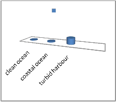
c(A)
0.15 0.3 2.19
Fig.1 These are the extinction coefficient values for different kinds of water.
2.PROPERTIES OF THE UNDERWATER OPTICAL WIRELESS COMMUNICATION CHANNEL
capture the multiple scattering in natural water, and also includes the polarization of light.
Here in this paper we present about three models of optical wireless communication 1.line of sight link (LOS) 2.Modulating retro reflector link 3.Reflective
Light pulses propagating in aquatic medium suffer from attenuation and broadening in the spatial, angular, temporal and polarization domains. The attenuation and broadening are wavelength dependent and result from absorption and multi-scattering of light by water molecules and by marine hydrosols (mineral and organic matter).
The extinction co-efficient c(A) of the aquatic medium
is governed by the absorption and scattering coefficient a(A) and f3(A), respectively, and we have
C (A) =a (A) +f3 (A) (1)
Figure (1) depicts the absorption, scattering, and extinction coefficient for three types of water – clean ocean water, coastal ocean water, and turbid harbor water. It is clear that increase in the turbidity dramatically increases the extinction coefficient from less than 0.1m-1 for pure water up to more than 2m-1 for turbid harbor water. However the absorption coefficient increases more moderately than does the turbidity.
The propagation loss factor as a function of
wavelength and distance z is given by
Lpr (A, z) =exp (-c (A) z) (2)
3. COMMUNICATION LINK MODELS
We now consider three types of communication links: the line of sight, the modulating retro reflector, and the reflective. In addition, we perform a bit error rate (BER) calculation.
3.1. Line-of-Sight Communication Link
Line of sight is a straight and unobstructed path of communication between transmitter and receiver. This is the most common link between two points in optical wireless communication system. The figure represents line of sight (LOS). In this scenario, the transmitter directs the light beam in the direction of the receiver. The optical signal reaching the receiver is obtained by multiplying the transmitter power, telescope gain, and
losses and is given by
IJSER © 2011 http://www.ijser.org
International Journal of Scientific & Engineering Research Volume 2, Issue 6, June-2011 3
ISSN 2229-5518
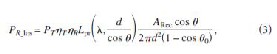
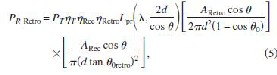
where PT is the average transmitter optical power, ijT is the optical efficiency of the transmitter, ijR is the optical efficiency of the receiver, d is the perpendicular distance between the transmitter and the receiver plane, 8 is the angle between the perpendicular to the receiver plane and the transmitter-receiver trajectory, ARecis the receiver aperture area, and 80 is the laser beam divergence angle. When the Transmitter beam divergence angle is very narrow (80‹‹IT/20), Eq. (3) can be approximated as
(4)
Fig.2. Shows the line of sight communication link.
3.2. Modulating Retro Reflector Communication
Link
A Modulating Retro Reflector (MRR) system combines an optical retro reflector and an optical modulator to allow optical communications and sometimes other functions such as programmable signage. The modulating retro-reflector link is used when one party (for example, a submarine) has more resources another one (for example, a diver), as in Fig (2). In this case, the submarine has more energy, payload, and lifting capacity than the diver. Therefore it would be wise to put most of the complexity and power requirement of the communication system into the submarine. In a modulating retro-reflector link, the interrogator sits at one end (in our case, in the submarine), and a small modulating optical retro-reflector sits at the remote end. In operation, the interrogator illuminates the retro-reflecting end of the link with a continuous wave
beam. The retro reflector in actively reflects this beam
back to the interrogator while modulating the information on it. The received power in this scenario is given by
Where ijRetro is the optical efficiency of the retro reflector, 8 is the angle between the perpendicular to the receiver plane and the transmitter-receiver trajectory, ARetro is the retro reflector’s aperture area, and 80Retro is the retro reflector’s beam divergence angle.
Fig.3. Shows the modulating retro reflective communication link
3.3. Reflective Communication Link
In some communication scenarios the line of sight is not available due to obstructions, misalignment, or random orientation of the transceivers.To address this problem a reflective communication link could be used. In this case, the laser transmitter emits a cone of
light, defined by inner and outer angles 8minand8max, in
the upward direction. Here 8i and 8t are the angles of incidence and of transmission, respectively. (The latter is derived from the former using Snell’s law).
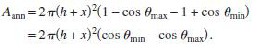
The light reaching the ocean-air surface illuminates an annular area and is partially bounced back in accordance with the reflectivity. Since the refractive index of air is lower than that of water, total internal reflection (TIR) can be achieved above a critical incidence angle. When the transmitter is at depth h, the illuminated annular surface with equal power density at depth x is given by
(6)
Equation (6)describes an annular area taken from a sphere of radius h+x, which would have uniform power density in free space .If we model the ocean-air
IJSER © 2011 http://www.ijser.org
International Journal of Scientific & Engineering Research Volume 2, Issue 6, June-2011 4
ISSN 2229-5518
surface as smooth, then 8=8i, and we can derive the link budget by using the variables defined in Eq. (3). Then we can define the auxiliary function and calculate the received power as
fR_ref(8) = PTcos8/Aann={ijTijRLpr(A,h+x/cos8)
1/2{[tan(8t-8)/tan(8t+8)]2+[sin(8-8t)/sin(8+8t)]2}
8min � 8 � 8c
{ijTijRLpr(A,h+x/cos8), 8c � 8 � 8max (7)
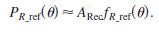
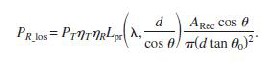
At the plane of the receiving sensor, node coverage is provided with in an annular area bounded by radii (h+x) Tan 8minand(h+x)Tan 8max. Equation (7)can be simplified on the assumption that the receiver aperture is small relative to h+x, yielding the approximate received power as
(8)
Fig.4 .Shows the reflective communication link
4. STIMULATION AND RESULTS
By using the values in table.1 we have simulated the loss at receiver end in the three scenarios using MATLAB. The results have been shown in the tables
below from table II to table XVI. This gives the
Fig (5) represents the eye diagram for LOS link for c (A)=0.3.since the eye is widely opened, we came to know that the ISI value is more. This leads to the reduction of expected data rate. In the fig (9) and fig (12) the eye patterns of the retro reflector link and reflective link has been given respectively. In both of them the noise levels are very high which results in ineffective communication between transmitter and receiver and data rate is reduced.
Table II, III, IV gives the receiver power of line of sight link at 8=300 at different distances and for three extinction coefficients. From this if we consider for distance d=20, the loss value is more in turbid harbour water than the other two. Table V, VI, VII gives the receiver power for line of sight link at different 8 values at a constant distance d=50m. From this we can know that the effectiveness of each water type changes with the change in value of 8. The same we can observe in modulating retro reflector link and reflective link also. Hence the turbid harbour water creates a bad impact on the data rate than the other two water types. Now if we consider table II and VIII the receiver power of LOS link and retro reflector link for coastal ocean water at constant 8=300 the loss is more in retro reflector link. Hence line of sight link is more effective than the other two links.
TABLE 1
These are the parameters used in the numerical calculation
consistency of receiver power in the three scenarios.
We have implemented the MATLAB results in OPTI SYSTEM. In opti system we have implemented spatial optical transmitter, spatial optical receiver, and OWC channel with required losses which were obtained in MATLAB. We have analysed the output of the receiver using different analysers such as RF spectrum analyser, oscilloscope visualizer, eye diagram analyser, BER calculator.
From fig (4) we can infer that for a time (bit period) of
0.3 to 0.75 the quality factor (Q) raises more than 2000.
Parameter value

Extinction coefficient for
• Retro reflector 0.9
• Transmitter 0.9
• Receiver 0.9
Transmitter power (W) 1
Receiver aperture area (m2) 0.01
IJSER © 2011 http://www.ijser.org
International Journal of Scientific & Engineering Research Volume 2, Issue 6, June-2011 5
ISSN 2229-5518
Retro reflector aperture area (m2) 0.01
Retro reflector beam divergence (8retro) 10 (deg)
Beam divergence angle 80 (deg) 68
Transmitter inclination angles 8min,8max
(deg) 0,68
Transmitter depth h (m) 20
Receiver depth x (m) 20

Fig.5.This graph shows BER analysis of Line of sight link at receiver side.
Fig.6. This graph shows eye diagram for Line of sight link.
Fig.7. This graph shows oscilloscope visualizer output for Line of sight link
Fig.8. This graph shows RF Spectrum analysis for line of sight link
IJSER © 2011 http://www.ijser.org
International Journal of Scientific & Engineering Research Volume 2, Issue 6, June-2011 6
ISSN 2229-5518
Fig .9. This graph shows BER analysis for Modulated
Retroreflector Link.
Fig .10.This graph shows eye diagram analysis for Modulated
Retro reflector Link
Fig.11. This graph shows oscilloscope visualizer for Modulated
Retro reflector Link
Fig .12. This graph shows RF Spectrum Analyser for Modulated
Retro reflector Link
IJSER © 2011 http://www.ijser.org
International Journal of Scientific & Engineering Research Volume 2, Issue 6, June-2011 7
ISSN 2229-5518
Fig.13. This graph shows eye diagram analysis for Reflective link
Fig.14. This graph shows Oscilloscope Visualizer for reflective link.
Fig .15. This graph shows RF Spectrum Analysis for Reflective
Link
TABLE 2
This gives the receiver power(pr) in db at different distance(d) for line of sight link at constant 8=30 in coastal ocean water.
This gives the receiver power(pr) in db at different distance(d) for line of sight link at constant 8=30 in clean ocean water.
d(m) | 0 | 10 | 20 | 30 | 40 |
Pr(db) | -27.4 | -35 | -42.5 | -50 | -57.5 |
TABLE 4
This gives the receiver power (pr) in db at different distance(d) for line of sight link at constant 8=30 in turbid harbour water.
d(m) | 0 | 10 | 20 | 30 | 40 |
Pr(db) | -27.4 | -137 | -247 | -356 | -466 |
TABLE 5
This gives the receiver power (pr) in db at various t values for line of sight link at constant distance d=50m in coastal ocean water.
8(deg) | 0 | 15 | 30 | 45 | 60 |
Pr(db) | -126 | 23 | -491 | -187 | 7.3 |
TABLE 6
This gives the receiver power (pr) in db at various t values for line of sight link at constant distance d=50m in clean ocean water.
8(deg) | 0 | 15 | 30 | 45 | 60 |
Pr(db) | -93.4 | -19.1 | -280 | -125 | -26.8 |
TABLE 7
This gives the receiver power (pr) in db at various t values for line of sight link at constant distance d=50m in turbid ocean water.
d(m) | 0 | 10 | 20 | 30 | 40 |
Pr(db) | -27.4 | -42.5 | -57.5 | -72.6 | -87.6 |
TABLE 3
TABLE 8
This gives the receiver power (pr) in db at different distance(d) for modulated retro reflector link at
constant 8=30 in coastal ocean water.
IJSER © 2011 http://www.ijser.org
International Journal of Scientific & Engineering Research Volume 2, Issue 6, June-2011 8
ISSN 2229-5518
TABLE 14
TABLE 9
This gives the receiver power (pr) in db at different distance(d) for modulated retro reflector link at constant 8=30 in clean ocean water.
d(m) | 10 | 20 | 30 | 40 | 50 |
Pr(db) | -93.4 | -120 | -142 | -162 | -181 |
TABLE 10
This gives the receiver power (pr) in db at different distance(d) for modulated retro reflector link at constant 8=30 in turbid harbour water.
d(m) | 10 | 20 | 30 | 40 | 50 |
Pr(db) | -297 | -528 | -753 | -977 | -1200 |
TABLE 11
This gives the receiver power (pr) in db at various t values for modulating retro reflector link at constant distance d=50m in coastal ocean water.
8(deg) | 0 | 15 | 30 | 45 | 60 |
Pr(db) | -235 | 63.93 | -966 | -358 | 31.19 |
TABLE 12
This gives the receiver power (pr) in db at various t values for modulating retro reflector link at constant distance d=50m in clean ocean water.
8(deg) | 0 | 15 | 30 | 45 | 60 |
Pr(db) | -170 | -21.8 | -543 | -234 | -37.2 |
TABLE 13
This gives the receiver power (pr) in db at various t values for modulating retro reflector link at constant distance d=50m in turbid harbour water.
This gives the receiver power (pr) in db at various t values for reflective link at constant h+x=40m in coastal ocean water.
8(deg) | 0 | 15 | 30 | 45 | 60 |
Pr(db) | -113 | 5.95 | -407 | -163 | -6.94 |
TABLE 15
This gives the receiver power (pr) in db at various t values for reflective link at constant h+x=40m in clean ocean water.
8(deg) | 0 | 15 | 30 | 45 | 60 |
Pr(db) | -87.3 | -28.1 | -238 | -113 | -34.3 |
TABLE 16
This gives the receiver power (pr) in db at various t values for reflective link at constant h+x=40m in turbid harbour water.
8(deg) | 0 | 15 | 30 | 45 | 60 |
Pr(db) | -441 | 438 | -2536 | -788 | 337 |
V.CONCLUSION
The results above indicate the losses at the receiver end for medium distances. From this we can observe that as the turbidity of the water increases (i.e. extinction coefficient) the absorption of the water increases. So the losses at the receiver end also increases. Thus the communication in turbid harbour water reduces the data rate and results in an ineffective communication.Among the scenarios we discussed, the line of sight scenario is most effective than other two. Additional improvements to the availability of the network could be achieved by a hybrid communication system that would include an optical transceiver and an acoustical transceiver. A hybrid communication system can provide high data rate transmission by using optical transceiver. When the water turbidity is high or the distance between the terminals is large, the system can be switch to low data rate using the acoustic transceiver, thereby increase in the average data rate and availability.

IJSER © 2011 http://www.ijser.org
International Journal of Scientific & Engineering Research Volume 2, Issue 6, June-2011 9
ISSN 2229-5518
REFERENCE

[1] Shalomi Arnon “Underwater optical communication” (2010).
[2] Milica Stojanovic “Wireless underwater communication system and networks: current achievements and future research challenges” (1994).
[3] I. F. Akyildiz, D. Pompili, and T. Melodia, “Underwater acoustic sensor networks: research challenges,” Ad Hoc Networks 3(3), 255-
256 (2005).

• P.vijaya kumar is working as assistant professor (AP(SRG)) in electronics and communication engineering. In SRM.university. PH NO:7358927171,email: vijayakumarp@ktr.srmuniv.ac.in
• S.S.K.prneeth is pursuing his B.Tech in electronics and communication engineering in SRM university.PH NO:
9176082100,email:pranusatya@gmail.com
• Romarsha.B.narender is pursuing his B.Tech in electronics and communication engineering in SRM university. PH NO:9791023649,email:romarshab@gmail.com
[4] J. Heidemann, W. Ye, J. Wills, A. Syed, and Y. Li, “Research challenges and applications for underwater sensor networking,” in Proc.
IEEE Wireless Communications and Networking Conf., pp. 228–235(2006).
[5] T. Dickey, M. Lewis, and G. Chang, “Optical
oceanography; recent advances and future directions using global remote sensing and in
situ observations,” Rev. Geophys. 44(1), RG1001 (2006). [6] C.Detweiller, I. Vasilescu, and D. Rus, “AquaNodes: an underwater sensor network,” in Proc. Second Int. Workshop on Underwater Networks, pp. 85–88, IEEE (2007).
[7] F. Hanson and S. Radic, “High bandwidth underwater optical communication,” Appl. Opt. 47(2), 277—283 (2008).
[8] B. Cochenour, L. Mullen, and A. Laux, “Spatial and temporal dispersion in high bandwidth underwater laser communication links,” in
Proc. IEEE Military Communications Conf., pp. 1–7 (2008).
[9] J. H. Smart, “Underwater optical communication systems part 1: variability of water optical parameters,” in Proc. IEEE Military Communications Conf., pp. 1140–
1146(2005).
[10] J. W. Giles and I. N. Bankman, “Underwater optical communications systems part 2: basic design considerations,” in Proc. IEEE Military
Communications Conf., pp. 1140–1146(2005).
[11] D. Kedar and S. Arnon, “Subsea ultraviolet solar- blind broadband free-space optics communication,” Opt. Eng. 48(4), 046001(2009).
[12] S. Jaruwatanadilok, “Underwater wireless optical communication channel modelling and performance evaluation using vector radiative
Transfer theory,” IEEE J. Sel. Areas Commun. 26(9),
1620–1627 (2008).
IJSER © 2011 http://www.ijser.org