Inte rnatio nal Jo urnal o f Sc ie ntific & Eng inee ring Re se arc h, Vo lume 3, Issue 2, February -2012 1
ISS N 2229-5518
Analysis of RF MEMS Square Spiral Inductor
Pushpinder Sharma ,Manish Mehta
Abs tract— This paper involves analysis of a physical model f or square spiral inductor on silicon. The impacts of changes in number of turns of square spiral inductor are studied extensively. The simplicity of the physical model enables a computational procedure f or eff iciently optimizing the inductance,resistance magnetic f lux density. Square spiral inductor from 2.5 to 9.5 turns are studied in f requency range of 1 to 10 GHz.
Index Terms— Inductance, Self -resonance f requency, Spiral Inductor optimization
.
—————————— ——————————
1 INTRODUCTION
Availability of goo d quality integrated inducto rs is an i m- portant factor which deter mine th e per for mance o f radio frequency integrated circuits [1]. The inductor is a basic componen t and very vital in designing radio frequency (RF) matching networ ks, load circuits of volta ge controlled oscillators, filters, mix ers and many o ther RF circuits [2]. It is a fundamental device that can be found in al most any RF circuit. In the past several methods are adopted to i mpro ve perfo rmance of inductor . Inductance and sel f-r esonant fr e- quency (SRF) of th e spiral induc tor in CMOS IC technolo- gies are limited by both high substrate capacitance and substrate loss.
II DESIGN OF INDUCTOR
Radio fr equenc y inductor is designed using c omsol multiphysics v 4.0. Co msol multiphysics is a finite element analyser, solver and Si mulation software used in vario us physics and engineering applications.
Width o f coil = 10 micro meter
Spacing betw een turns=10 micro -meter. For 9.5 turns inductor
Internal diameter=40 micr o-meter .
Outer diameter=510 micro meter .
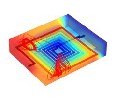
After designing induc tor por t is given at input of fixed cu r- rent density and outpu t is grounded . Two ou ter box is created outside inductor which is given air and inducto r is given silver material. El ectric and magnetic insulation is provid ed at outside boundry. In this case internal diameter is kept c onstant and external diameter varies with number of turns. As nu mber of turns increases inductance and magnetic energy increases. Inductance a mong materials is found highest for silver 6.83nH and lowest for chr omiu m
6.54nH for these particular di mensions .
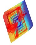
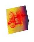
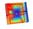
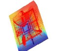
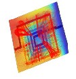
Figure 1.1&1.2 repr esents 2D and 3D structu res of square Spiral inductor r especti vely. Inside diameter is 40 micro meters and turns are incr esed th ere after till 9 .5 innermost turn is connected to outpu t with the help o f air bridge .
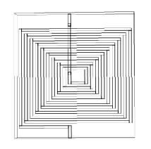
Figure1.1 2D VIE W OF 9.5 S QUAR E SPIR AL INDU CT OR
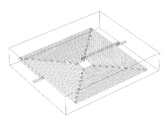
Figure1.2 3D VIEW OF 9.5 SQUARE SPIRA L IN DU CTOR
.
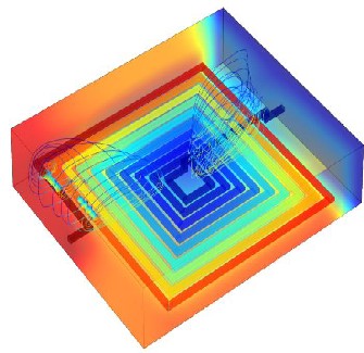
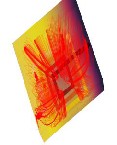
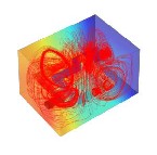
Figure 1.3 rep resents magnetic flux lines passing between turns of induc tor on injection of curr ent
IJSER © 2012
http :// www.ijser.org
Inte rnatio nal Jo urnal o f Sc ie ntific & Eng inee ring Re se arc h, Vo lume 3, Issue 2, February -2012 2
ISS N 2229-5518
Figu re 1.5 s -parameters of 9.5 turn inductor
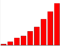
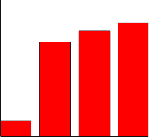
Figur e 1.4 show s inductance in nano henry v/s number of turns .9.5 turns inductor gives highest inductance value that is 6.8nH Inductance incr eases w ith number of tur ns.
Figur e 1.5 show s S-par ameters and Self Resonant fr equen- cy. Inductor s have both inductive and capacitance tenden- cies. SRF is the fr equency, that an inductor takes on enough of the capacitive tendencies that they cancel out the indu c- tive tendencies, thus r ender ing this device useless as an inductor. At this fr equency the inductor acts pur ely r esi s- tive and above this fr equency w ill b egin to act like a capaci- tor
Inductance of 9.5 inductor
Fig 1.3. M agnetic f lu x density lines

7.00E-009
6.00E-009
5.00E-009
4.00E-009
Inductance
6.90
6.85
6.80
6.75
6.77nH
6.81nH
Inductance

6.83nH
3.00E-009
2.00E-009
1.00E-009
6.70
6.65
0.00E+000
2 3 4 5 6 7 8 9
number of turns of inductor
6.60
6.55
6.54nH
Figure 1.4 Indu ctance with resp ect to number of turns
6.50
Cr Zn gold silver
materials
Ansoft Corporation
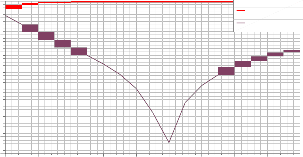
0.00
XY Plot sparameters
Curve Info
HFSSDesign2
-5.00
-10.00
-15.00
-20.00
-25.00
-30.00
-35.00
-40.00
-45.00
dB(S(WavePort1,WavePort1)) Setup1 : Sweep1
dB(S(WavePort1,WavePort2)) Setup1 : Sweep1
1.00 2.00 3.00 4.00 5.00 6.00 7.00 8.00 9.00 10.00
Freq [GHz ]
Fig.1.6 Inductance of 9.5 inductor v/s M EM S materials.
Inductance is ploted with respec t to materials. Materials are Silver , Gold , Zinc and Chr omiu m. Silver gi ves highest inductance of 6.83nH. Sil ver posses conducti vity of 61e6
S/m. G old c onductivity is 45.6e6 S/ m . Zinc conducti vity is 16.7 e6 S/m and chro miu m conduc tivity is 7.9e6 S/ m.
We obtain inductance value 6.54 nanohenry which is min- imum for chr omuium, next we get 6.77 nanohenry induc-
IJSER © 2012
http :// www.ijser.org
Inte rnatio nal Jo urnal o f Sc ie ntific & Eng inee ring Re se arc h, Vo lume 3, Issue 2, February -2012 3
ISS N 2229-5518
tance o f zinc and Gold material gi ves us 6.81 nanohenry inductance.
.
Conclusion and results
Inductors ar e studi ed extensively fro m 2.5 to 9.5 tu rns in comsol muliphysics ac/dc module. W e found that induc- tance, magnetic energy, and r esistance increases wi th nu m- ber of turns. Inductance a mong materials is found highest for silver6.83nH and lowest for chro mium 6.54nH
Table1.1 RF ME MS Inductor (silver ) induc tance, r esistance and energy with respect to number of turns
4.5 turn inductor
3.5 turn inductor
2.5 turn inductor 1.5 turn inductor
.
8.5 turn inductor
7.5 turn inductor
6.5 turn inductor
5.5 turn inductor
References
[ [1] J.M. Lo pe z-V illeg as, “Improve me nt o f quality fac to r o f RF Inte g rate d induc to rs by Layo ut o ptimizatio n”, Mic ro wave Theo ry and Tec hnique s, IEEE Transac tio ns o n pp.: 76 – 83,Jan 2000
[ [2]See Guan Hue “RF S piral Planar Induc to r Desig ns”,Asia-Pac ific Co nfe-
re nce o n Applie d Elec tro mag ne tic s pp. 1-20 ,july 2004.
Figure 1.7 1.5 to 8.5 tu rns of inductor
IJSER © 2012
http :// www.ijser.org
Inte rnational Jotunal of Scientific & Ergineerirg Research, Volume 3, Iss2, February-2012 4
ISSN 2229-5518
IJSER 2012
tttp'((ww .,, ser .rra