The research paper published by IJSER journal is about Analysis of Handover Initiation using Path Loss to Sustain QoS 1
ISSN 2229-5518odd page
Analysis of Handover Initiation using Path Loss to Sustain QoS
Dinesh Sharma & R.K.Singh
System for Mobile Communications (GSM).
—————————— ——————————
minimizing an operational network to congregate the
GSM is the first digital standard which was available for the commercial purpose and totally depends on circuit–switching. The whole principle of cellular network is based on the replacement of a single powerful transmitter with many others low power transmitters. Each low power transmitter covers a smaller area called a cell. All mobile systems agree to take the techniques like frequency reuse, cell division and automatic switching in other cells. Cellular networks are fully based on the technique of frequency reuse, so that the limited radio spectrum will receive maximum use, as shown in Fig.1. In cellular radio networks, a small area is covered by one base station and other base stations are installed with small overlapping areas. Neighbouring cells require using different frequencies to evade interference, but the same frequency can be reused in distant cells. The entire coverage area is splitter into many small hexagonal cells so that to increase the capacity of entire network and a decrease in the reuse of frequency [1]. Now days the network traffic scenario is completely varied and each traffic type have its own requirements in terms of bandwidth, delay, loss and availability. To determine the service level provided by the network, a number of QoS parameters are measured and monitored. The network performance of GSM and QoS assessment are the two significant steps for the mobile operators like the income and customer satisfaction is directly related to network performance and quality. Radio frequency network planning level (RNL) team plays a very major and vital role in
increasing demands from the Product end users.
————————————————
![]() Dinesh Sharma, Research Scholar, UTU, Dehradun (India). E-mail: sharma82dinesh@gmail.com
Dinesh Sharma, Research Scholar, UTU, Dehradun (India). E-mail: sharma82dinesh@gmail.com
![]() R.K.Singh, Professor (OSD, UTU,Dehradun (India).
R.K.Singh, Professor (OSD, UTU,Dehradun (India).
E-mail:rksinghkec12@rediffmail.com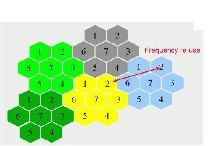
Fig. 1 Concept of cell and frequency reuse
Generally the following responsibilities are assigned to RNL
team [2]:![]()
To develop the present network coverage and ability. To improve the given service quality to full fill customer needs.
![]() To uphold the key performance indicators already
To uphold the key performance indicators already
defined threshold.
IJSER © 2012 http://www.ijser.org
The research paper published by IJSER journal is about Analysis of Handover Initiation using Path Loss to Sustain QoS 2
ISSN 2229-5518odd page
![]() To maintain the QoS criteria being compulsory by
To maintain the QoS criteria being compulsory by
country’s regulatory authority.
![]() To standardize the network performance with that of
To standardize the network performance with that of
competitor’s network to magnetize more customers;
keeping a stability between cost and quality.
![]() To efficiently use the obtainable bandwidth and frequency carriers so that to avoid interference inside the network and service humiliation.
To efficiently use the obtainable bandwidth and frequency carriers so that to avoid interference inside the network and service humiliation.
To increase the mobility for apparent Communications while travelling from one particular place to another place by train or car or plane or even while walking, the Mobile systems use wireless technology. Throughout the arrangement of a connection the radio reception of signal is predicted to change considerably, and the existed location of the mobile device may be at a long distance from its starting point. But the mobile telephony is produced with distinct connections to all the base stations providing Cells of coverage, a traditional system is formed such that irregular connections are hidden from the user [3]. QoS is generally used in every scenario where quality of a system is mentioned. The term QoS is considered as the ability to give declaration that the requirements of all applications must be satisfied. Depends on the particular type of application, QoS in GSM can be considered by reliability, robustness, availability, and security, among others. GSM Network service providers study the network performance and estimate service quality indicators [4-7]. These service quality indicators are used for the following purposes:![]()
To control and plan Broadcast channel.
To detect network problems in one or more BTS and finally invent a way to minimize the problem in the network and implement corrective actions like new frequency allocations, antenna adjustment, and parameter modification etc..
![]() To standardize the network in the competition of another network so that to catch the attention of more users at the cost of better quality.
To standardize the network in the competition of another network so that to catch the attention of more users at the cost of better quality.
![]() To forecast the impending traffic evolution and network expansion as per increasing mobile users.
To forecast the impending traffic evolution and network expansion as per increasing mobile users.
![]() To keep an eye on system behaviour and inconsistency in terms of traffic load, congestion, successful attempts etc. (site audit reports).
To keep an eye on system behaviour and inconsistency in terms of traffic load, congestion, successful attempts etc. (site audit reports).
![]() To find the regular faults obtain in the BSS
To find the regular faults obtain in the BSS
(hardware) and to ensure resource accessibility.
Path loss plays vital role to decide the QoS for wireless communication at network planning level (NPL). Path loss
causes poor signal strength at the receiver side [8]. So that the
receiver is not able to detect the original signal. All wireless communication operators use Key Performance Indicators (KPIs) to judge their network performance and they evaluate the Quality of Service (QoS) regarding end user perspective. All the events being occurred over air interface are triggering different counters in the Base Station Controller (BSC). To measure path loss we have many more models.
Path loss plays very important role at Network planning level. Path loss (or path attenuation) is an unwanted introduction of energy tending to interfere with the proper reception and reproduction of the signals during its journey from transmitter to receiver [9]. It reduces power density (attenuation) of an electromagnetic wave as it propagates through space. Radio wave signal path loss is an important one in the analysis and design of a radio communication system. The signal path loss generally determines many parameters of the radio communications system like transmitter power, and the antennas, especially their gain, height and general location. The path loss also affects other parameters such as necessary receiver sensitivity, the form of transmission used and many other factors. Due to this, it is essential to realize the reasons for radio path loss, and to be capable to determine the levels of the signal loss for a give radio path. The path loss is repeatedly mathematically and these calculations are repeatedly undertaken to prepare the coverage or system design activities Therefore, path loss calculations are used in many radio and wireless survey tools determine signal strength at different locations. This type of wireless survey tools are used to help determine the radio signal strengths before installing the equipment. The installation of macro cell base station is very high so before installation radio coverage surveys are important.
Signal path loss can be caused by many factors. In a global environment there are many factors that affect the actual RF path loss. When planning any radio or wireless system, it is necessary to have a broad understanding the elements that give rise to the path loss, and in this way design the system accordingly. The following are some of the major elements causing signal path loss for any radio wave system [10, 11].
![]() Free space loss: This loss occurs as the signal travels from transmitter to receiver through space without any other effects attenuating the signal. The energy of any signal decreases when it travels a larger distance in the space according to the conservation of energy.
Free space loss: This loss occurs as the signal travels from transmitter to receiver through space without any other effects attenuating the signal. The energy of any signal decreases when it travels a larger distance in the space according to the conservation of energy.
![]() Absorption losses: These losses occur when the radio signal passes into a medium like large buildings and foliage which are not totally transparent to radio
Absorption losses: These losses occur when the radio signal passes into a medium like large buildings and foliage which are not totally transparent to radio
IJSER © 2012 http://www.ijser.org
The research paper published by IJSER journal is about Analysis of Handover Initiation using Path Loss to Sustain QoS 3
ISSN 2229-5518odd page
signals. This can be explained by the travelling of a
light signal passing through a transparent glass. The terrain over which signals travel will have a major effect on the signal. The hills obstruct the path and considerably attenuate the signal, time and again making reception impossible. We can take an example on the Long Wave band; it found that signals travel better over more conductive terrain, e.g. sea paths. Dry sandy terrain gives higher levels of attenuation. Buildings and other obstructions including vegetation have a significant effect. the buildings reflect radio signals and they also absorb them. Trees and foliage can attenuate radio signals, particularly when wet.
![]() Diffraction: This type of losses occurs when an
Diffraction: This type of losses occurs when an
obstruction unexpectedly appears in the path. The signal diffracts around the object, and losses occur. Radio signals tend to diffract more at sharp edges.
![]() Multipath: In a real global environment, signals will be reflected and they will reach the receiver via a number of different paths. These signals may add or subtract from each other depending upon the relative phases of the signals. This entire process leads to a loss which is multipath loss. Mobile receivers (e.g. Mobile phones) are subject to this effect which is known as Rayleigh fading.
Multipath: In a real global environment, signals will be reflected and they will reach the receiver via a number of different paths. These signals may add or subtract from each other depending upon the relative phases of the signals. This entire process leads to a loss which is multipath loss. Mobile receivers (e.g. Mobile phones) are subject to this effect which is known as Rayleigh fading.
![]() Atmosphere: The atmosphere also affects radio signal
Atmosphere: The atmosphere also affects radio signal
paths. It affects at lower frequencies, especially below
30 - 50MHz, the ionosphere has a major effect, reflecting them back to Earth. At frequencies above
50 MHz and more the troposphere has a major effect on the radio signal path. For UHF broadcast this can extend coverage to approximately a third beyond the horizon.
One of the main reason to understand the different elements affect the path loss is to be capable to forecast the loss for a particular path, or to forecast the coverage that may be achieved for a given base station and broadcast station. The prediction of the path loss is not easy for real life global applications, because for that purpose it has to consider many factors into account. In spite of this there are many wireless radio coverage prediction software programs and wireless survey tools that are available to predict radio path loss. Some of the path loss models are as follows [12]-
a. Simplified Path Loss Model
b. Stanford University Interim (SUI) Model
c. Okumura’s Model
d. Hata Model
e. COST231 Extension to Hata Model
f. ECC-33 model
g. Walfisch- Bertoni Model h. Longley rice model
i. Egli Propagation Model j. Bullington model
k. Epstein-Peterson model
The coverage area in cellular mobile communication is divided into number of cells. Each cell is covered by An individual base station [13]. When a mobile unit is moving from one cell area to another adjacent cell area Handover takes place. It is defined as the process of changing the current radio channel to a new radio channel [14]. It is a flawless service to active mobile phone users while data transfer is in progress. Handover is an expensive process to execute, so unnecessary handovers should be avoided. Handover includes two major steps, first handover initiation; In this initiation phase, decision to start the handover procedure is taken. Second is, handover execution; in this execution phase, a new channel assignment is carried out or if there is no channel available, the call is dropped [15].
There are different categories of GSM handover which involves different parts of the GSM network. Changing cells within the same BTS is not complicated as the changing of the cell belonging to different MSC. There are mainly two reasons for this kind of handover. The mobile station moves out of the range station or the antenna of BTS respectively. Secondly the wire infrastructure the MSC or the BSC may decide that the traffic in one cell is too high and move some to other cells with lower load. Following are the main different kinds of handover [16-18]:
(a) Intra-cell BTS Handover: The terms intra-cell and intra BTS
handover are used both for frequency change. There is a slight
between them but usually they are considered the same. The term intra-cell handover in not real as it deals with the frequency change of a going call. The frequency change occur when the quality of the communication link degrading and the measurements of the neighboring cells better than the current cell. In this situation the BSC which controls the BTS serving the MSC order the MSC and BTS to switch to another frequency which offers better communication link for the call. The communication link degradation is caused by the interference as the neighboring cell using the same frequencies and its better to try another channel. In the intra BTS handover cell involved are Synchronized.
(b) Intra-BSC Handover: The intra-BSC handover is performed when the MSC changes the BTS but not the BSC. The intra- BSC handover is entirely carried out by the BSC, but the MSC is notified when the handover has taken place. If the targeted
IJSER © 2012 http://www.ijser.org
The research paper published by IJSER journal is about Analysis of Handover Initiation using Path Loss to Sustain QoS 4
ISSN 2229-5518odd page
cell is in different location area then the MSC needs to perform
the location updates procedure after the call. In the intra-BSC handover both synchronized and non synchronized handover are possible.
(c) Intra-MSC Handover: In the intra-MSC handover when the
BSC decides that handover is required but the targeted cell is controlled by different BSC then it needs assistance form the connected MSC. In comparison to the pervious handover discussed the MSC mandatory for this kind of handover. Responsibilities of the MSC do not include processing the measurements of the BTS or MSC but to conclude the handover. This kind of handover can be other intra-MSC or Inter-MSC. In the intra-MSC handover the targeted cell is allocate in different BSC connected by the same MSC. The MSC contacts the targeted BSC for allocation of the required resources and inform the BSC when they are ready. After the successful resources allocation the MSC instructed to access the new channel and the call is transferred to the new BSC.
(d) Inter-MSC Handover: The inter-MSC handover is performed when the two cells belonging to different MSC in the same system. In the inter-MSC handover the targeted cell is connected is connected to different MSC than the one currently serving the call MSC
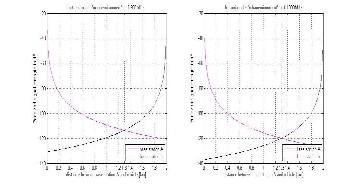
By monitoring the radio link, Decision is taken for commencing handover process and the selection of new station [2]. The parameters measured to determine handover are usually the received signal strength, the signal to noise ratio and the bit error rate [4]. Here, we will use received signal strength to determine handover process. RSS measurements are affected by distance dependent fading (or path loss), log normal fading (i.e. shadow fading) and Rayleigh fading (i.e. multipath fading). Ideally, the handover decision should be based on distance dependent fading and, to some extent, on shadow fading. The following values were assumed for the model parameters:
f = 900 and 1800MHz pt1 = 43 dBm
pt2 = 33 dBm
D (Distance between adjacent stations) = 2000 m. Height of receiving antenna= 1.5m
Height of Transmitting antenna= 35 m
Building Height = 15 m (For Bertoni model)
The received signal strength and Path loss from both the stations using different path loss models are calculated and plotted versus distance at two different frequencies 900 and
1800 MHz is shown in following figures.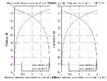
Fig. 2 Variation of Path loss with distance in Hata Model at 900 and 1800

MHz
Fig. 3 Variation of RSS with distance in Hata model at 900 and 1800 MHz
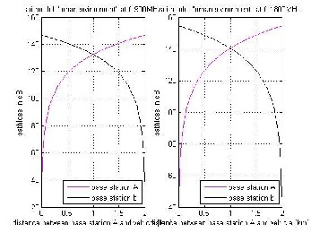
Fig. 4 Variation of Path loss with distance in SUI Model at 900 and 1800
MHz
IJSER © 2012 http://www.ijser.org
The research paper published by IJSER journal is about Analysis of Handover Initiation using Path Loss to Sustain QoS 5
ISSN 2229-5518odd page
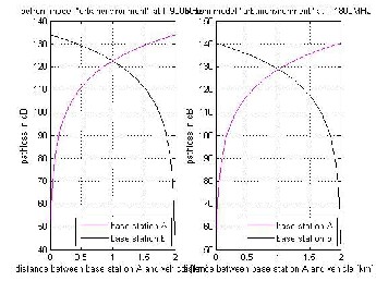
Fig. 5 Variation of RSS with distance in SUI Model at 900 and 1800 MHz
Fig. 6 Variation of Path loss with distance in Bertoni Model at 900 and
1800 MHz
Fig. 7 Variation of RSS with distance in Bertoni Model at 900 and 1800
MHz
In this paper we discussed the depth the GSM network architecture, QoS requirement and path loss. Along with the most important procedure of GSM handover initiation,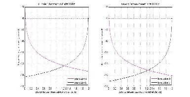
handover types and their measurements reports to ensure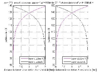
mobility in GSM network and to emphasis the fact that handover in GSM network are very important to maintain the quality of service. The different path loss models like Hata, Cost-231, SUI and Bertoni for macro cells were used and then the received signal strength and from the base stations was calculated to determine which model minimized the number of handoffs in urban environment. In SUI model the handover occurs at lower distance as compared to the Hata, Cost-231 and Bertoni path loss models. And the handovers by using the cost-231 models gives at larger distance. Hence the Cost-231 path loss model should be used to postpone the handovers to sustain the QoS.
Fig. 8 Variation of Path loss with distance in Cost-231 Model at 900 and
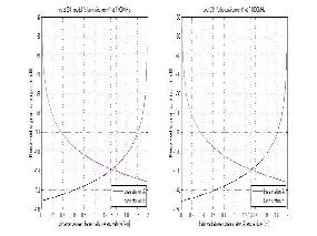
1800 MHz
Fig. 8 Variation of Path loss with distance in Cost-231 Model at 900 and
1800 MHz
[1] Angelos Amanatiadis, Konstantinos Drakatos, Loukas Tsironis, Vassilis Moustakis, “Defining the Main Factors of Quality of Service in Mobile Telephony”, 2006 IEEE.
IJSER © 2012 http://www.ijser.org
The research paper published by IJSER journal is about Analysis of Handover Initiation using Path Loss to Sustain QoS 6
ISSN 2229-5518odd page
[2] Bilal Haider, M. Zafrullah, M.K. Islam, “Radio Frequency
Optimization & Evaluation in operational GSM Network” in WCECS
2009.
[3] Dan Chalmers and Morris Sloman “ A Survey of Quality of Service in Mobile Computing Environments”, IEEE Communications Surveys Second Quarter 1999.
[4] El-Gendy, M. A.; Bose, A.; Shin, K. G. Evolution of the Internet QoS
and support for soft real-time applications. Proceedings of the IEEE 2003,
91(7), 1086-1104.
[5] Chen, D.; Varshney, P. K. QoS Support in Wireless Sensor Networks: A Survey. In Proc. of the Int. Conf. on Wireless Networks, Las Vegas, USA, June 2004.
[6] Li, Y.J.; Chen, C.S.; Song, Y.-Q.; Wang, Z. Real-time QoS support in wireless sensor networks: a survey. In Proc of 7th IFAC Int Conf on Fieldbuses & Networks in Industrial & Embedded Systems (FeT'07), Toulouse, France, Nov. 2007.
[7] Bouyssounouse, B. ; Sifakis, J. (eds.) Embedded Systems Design: The ARTIST Roadmap for Research and Development. Lecture Notes in Computer Science 3436, Springer-Verlag, 2005.
[8] Dinesh Sharma, R.K. Singh “The Effect of Path Loss on QoS at NPL”
International Journal of Engineering Science and Technology (IJEST). [9] public domain material from the General Services Administration document "Federal Standard 1037C" (in support of MIL-STD-188).
[10] http://www.radio-electronics.com/info/propagation/path-loss/rf-
signal-loss-tutorial.php.
[11] T.S. Rappaport, Wireless Communications - Principles and Practice,
2nd Edition, Prentice Hall , 2001.
[12] Dinesh Sharma, Purnima K. Sharma, Vishal Gupta, R.K.Singh, “A Survey on Path Loss Models used in Wireless Communication System Design” in IJRTE Vol. 3, No. 2 in 2010.
[13] G.P. Pollini , “Trends in Handover Design”, IEEE Communications
Magazine , pp. 82 – 90, March 1996 .
[14] V.T. Vakili & S.S. Moghaddam , “Optimum Selection Of Handoff
Initiation Algorithm & Related Parameters”, DSP Research Lab.
[15] G.E. Corazza & Others, “Characterization Of Handover Initialization
in Cellular Mobile Radio Networks”, IEEE VTC 94, pp. 1869 –1872, 1994. [16] Thomsen J. and Manggard R., “Analysis of GSM Handover using coloured Petri Net” Master thesis, university of Aarhus, Denmark in 2003. [17] Wei Y., “Evaluation of Roaming and download Times in Universal Cellular/Wireless LAN system”, Master Thesis Disseration, Concordia, Canada in 2001.
[18] Jahangir Khan, “ Handover Management in GSM Cellular System”,in
International journal of Computer Applications, vol. 8-No.12, page no.14-
24, October 2010.
Mr Dinesh Sharma was born on 5th Dec 1982 in Narnaul District Mohindergarh of Haryana (India).He received his M.Tech. degree in Communication Engineering from SHOBHIT University, Meerut, India. He is a Associate Member of the IETE. He has published several Research papers in national and international journals/conferences. He is presently research scholar in UTTARAKHAND TECHANICAL UNIVERSITY, Dehradun (INDIA). His present research interest is in Signal Processin g and Wireless Communication.
area of Microelectronics, Fiber Optic Communications, and Solid State Devices. He has published several research papers in seminar/conference and journal papers. He is member of several institutional and educational and educational bodies. Before joining Kumaon Engineering College, Dwarahat, he has worked in Birla Institute of Technology and Sciences (BITS), Pilani, and Central Electronics Engineering Research Institute (CEERI) Pilani. At present he is serving as OSD, in newly established Technical University of Uttarakhand known as Uttarakhand Technical University, Dehradun.
Dr. R.K. Singh Professor, KEC, Dwarahat, Almora , Jointly submitting research and development project in UCOST, Uttarakhand. He is member of academic staff of Kumaon Engineering College, Dwarahat, Almora, where he is a professor in the department of Electronics and Communication Engineering. Dr. Singh has given his contribution to the
IJSER © 2012 http://www.ijser.org