International Journal of Scientific & Engineering Research, Volume 5, Issue 7, July-2014 52
ISSN 2229-5518
An introduction to Inverters and Applications for system design and control wave power
Alimorad Khajehzadeh1, Moslem Amirinejad2, Sasan Rafieisarbejan3
Abstract:
Inverters are used in a large number of power applications. The function of an inverter is to convert DC power to AC, these are referred to as Voltage Source Inverters (VSI). VSI are divided up into three categories: Pulse-width Modulated Inverters, Square-wave Inverters, and Single-phase Inverters with Voltage Cancellation. This paper will talk about the different types of Inverters and how they work. It will continue on with examples of some types of inverters and what types of factors affect their efficiencies.
—————————— ——————————
I. INTRODUCTION
Within the last decade, there have been major advancements in power electronics. Power electronics have moved along with these developments with such things as digital signal processors being used to control power systems. An Inverter is basically a converter that converts DC-AC power. Inverter circuits can be very complex so the objective of this paper is to present some of the inner workings of inverters without getting lost in some of the fine details. A voltage source inverter (VSI) is one that takes in a fixed voltage from a device, such as a dc power supply, and converts it to a variable-frequency AC supply.
Voltage-source inverters are divided into three general
categories: Pulse-width Modulated (PWM) Inverters, Square-wave Inverters, and Single-phase Inverters with Voltage Cancellation. Pulse-width modulation inverters take in a constant dc voltage. Diode-rectifiers are used to rectify the line voltage, and the inverter must control the magnitude and the frequency of the ac output voltages. To do this the inverter uses pulse-width modulation using it’s switches. There are different methods for doing the pulse- width modulation in an inverter in order to shape the output ac voltages to be very close to a sine wave. These different
————————————————
Research Branch, Islamic Azad University, Kerman, Iran (E-mail:
amirinejadmoslem@yahoo.com ).
methods will be discussed further with a focus on
sinusoidal-PWM. Squire-wave inverters have their input connected to a controlled dc voltage in order to control the magnitude of the output ac voltage. The inverter only controls the frequency of the output where the input voltage is controlled the magnitude. The output ac voltage has a waveform similar to a square wave which is where the inverter got its name. Lastly, Single-phase inverters with voltage cancellation take in a constant dc source and output a square-wave like ac voltage. They can control both the frequency and the magnitude of the output but do not use PWM and therefore have a square-wave like output. These inverters have combined characteristics of the previous two inverters. The voltage cancellation only works with single phase inverters, not three phase, this will be explained more further later on in the paper.
Switch-mode dc-to-ac inverters are used in ac-motor drives and uninterruptible ac power supplies where the main objective is to provide a sinusoidal ac output where magnitude and frequency can both be controlled.
II. CLASSIFICATION OF POWER ELECTRONIC DEVICES
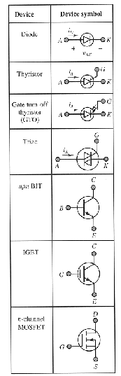
There are five main groups of power semiconductors. They are: power diodes, thyristors, power bipolar junction transistors (BJTs), insulated gate bipolar transistors (IGBTS), and static induction transistors (SITs). Figure 1 gives a picture of each.
IJSER © 2014 http://www.ijser.org
International Journal of Scientific & Engineering Research, Volume 5, Issue 7, July-2014 53
ISSN 2229-5518
A. Power Diodes
These devices function identically to any other standard diode except that they are able to handle much more current. There are three main types of power diodes: general-purpose, high-speed (fast-recovery), and Schottky. Typical ranges for these devices are around 3000 V and 3500
A for general-purpose diodes and 3000 V and 1000 A for high-speed devices. High speed devices can switch on the order of a microsecond whereas a schottky diode is much fast and is in the nanosecond range. The schottky diodes, however, are limited to around 100 V and 300 A. The forward voltage drop over power diodes is usually negligible compared to the voltages that they are in. But the voltage drop is similar to normal diodes and is between 0.5
V and 1.2 V. [1]
B. Thyristors
These devices are similar to power diodes except that they have an additional gate terminal that controls the time when the device begins conducting. Provided that the anode voltage is greater than the cathode voltage, a small gate current will allow the device to conduct. The forward voltage drop of a thyristor is between 0.5 V and 2 V. Once conduction is initiated the gate current has no further control. In order to stop conduction the device must be in reverse-biased; the anode voltage is less than the cathode voltage. These devices are rated up to 6000 V and 3500 A. The turn-off time of these devices is the time it takes for the device current to go back to zero after putting the device in reverse-bias. The fastest turn-off times are around 10 microseconds. To achieve these turn-off times devices with lower power ratings must be used. Thyristors are further classified into the following groups: force-commutated and line-commutated thyristors, gate turn-off thyristors (GTOs), reverse-conducting thyristors (RCTs), static induction thyristors (SITs), gate-assisted turn-off thyristors (GATTs), light-activated silicon controlled rectifiers (LASCRs), and MOS controlled thyristors (MCTs). These devices are all basically a modification of the standard thyristor.
Shown in figure 1 is a triac device. This is basically two thyristors connected back to back to allow control both forwards and backwards. A triac is basically a bidirectional thyristor. The gate turn-off thyristor (GTO), can be turned on by applying a short positive pulse to the gate, like a thyristor, and can also be turned off by applying a short negative pulse. GTOs are very convenient in that they do not need to have other circuits to control in order to be turned off. [1]
C. Power BJTs
These devices are rated up to 1200V and 400A. They operate very much the same as a normal BJT. Power BJTs are used in power converters such as inverters as frequencies of up to 10 kHz. Power MOSFETs can operate at somewhat higher frequencies (a few to several tens of kHz), but are limited to power ratings, usually 1000 V, 50 A. Insulated-gate bipolar transistors (IGBTs) are voltage controlled power transistors that offer better speed than a BJT but are not quite as fast as a power MOSFET. [1]
D. Device History
The earliest switches used to oscillate were mechanical vibrators. Essentially oscillating mechanical relays, these devices were not very efficient or reliable. It was not until the 1960s when semi-conductors were being discovered and the transistor started to make an appearance. Now the Silicon Controlled Rectifier was made that worked as
IJSER © 2014 http://www.ijser.org
International Journal of Scientific & Engineering Research, Volume 5, Issue 7, July-2014 54
ISSN 2229-5518
electronic latching relays. Next the Darlington transistors
were used. These last two devices did prove to be both reliable and somewhat efficient but still had disadvantages. When the Metal Oxide Semi-conducting Field Effect Transistor (MOSFET) came out, it solved a lot of problems. These devices can handle high currents and have a low resistance. They are easy to connect in a circuit and work well in parallel connections allowing for more current. Some inverters now use the newer IGBTs which are newer, high power, and low less switching transistors.
III. HOW IT WORKS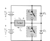
A. Simple Explanation
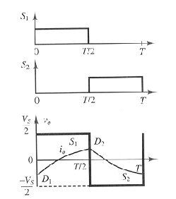
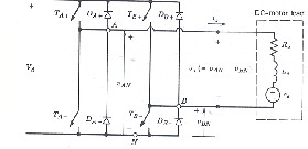
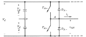
Figure 1 shows a half-bridge voltage source inverter. The switches can be bipolar, MOS transistors, or thyristors. The circuit works by turning switch 1 on, the output voltage is then the positive half-cycle, meaning that it will be Vs/2. To get the negative half-cycle, switch 2 is turned on and switch 1 is turned off. The order of this is actually reversed, switch 1 must be turned off first in order to avoid any short
circuit. Voltage outputs of this simple half-bridge inverter are shown in figure 2. If the load is always inductive, the
load current, io , will lag the voltage waveform, also shown in figure 2. It is shown that the current is sometimes negative when the voltage is positive. The diodes function to conduct the load current whenever it is opposite polarity
to that of the voltage. If the diodes were not present then the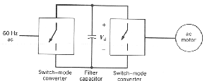
load current would not exist. Figure 2 also shows that D1 is conducting during the first half of the cycle and D2 during the second half.
Drive
The switch-mode inverter used to drive an AC motor in figure 3 is actually a converter where power can flow in both directions. Take for example if the motor was in a car. Normally it will require power as it must power the car, however, when the car is breaking it could be reversed, and used to generate power. The idea is that the motor has kinetic energy, since it would of already been spinning, it can then be slowed down and used as a generator. When this happens power would flow from the AC side to the DC side. This can then be dissipated through a resistor or fed back into the power grid to be used. In order to feed power back into the grid the converter that connects the drive to the utility grid must be a two-quadrant converter with reversible DC current. It must be able to operate as a rectifier when it is driving the motor and as an inverter when the motor is being used as a generator. [2]
B. Basic Concepts
Looking at a single-phase inverter, shown in figure
4a, the output voltage of the inverter is filtered so that it will be much more sinusoidal. This will take out some of the harmonics produced from the internal electronics of the inverter. The inverter will supply an inductive load meaning that the output current is going to lag the output voltage (see figure 3b). In intervals 2 and 4 the current and voltage have opposite signs meaning that power will flow from the ac side to the dc side of the inverter. It is necessary to have the inverter operate in all four of these intervals. In figure 4 it shows a full-bridge rectifier, where the output voltage can be of either polarity independent of the direction
IJSER © 2014 http://www.ijser.org
International Journal of Scientific & Engineering Research, Volume 5, Issue 7, July-2014 55
ISSN 2229-5518
of the output current. Figure 6 only shows one of the legs from the full-bridge converter shown in figure 4.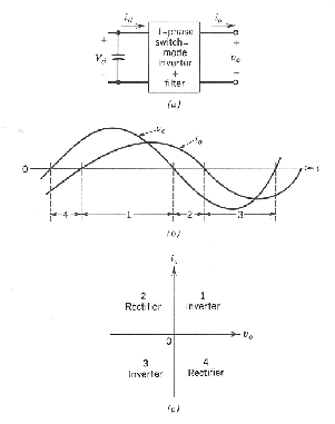
C. Pulse-Width Modulated (PWM)
Inverters that use PWM switching techniques have a DC input voltage that is usually constant in magnitude. The inverters job is to take this input voltage and output ac where the magnitude and frequency can be controlled. There are many different ways that pulse-width modulation can be implemented to shape the output to be AC power. A common technique called sinusoidal-PWM will be explained. In order to output a sinusoidal waveform at a specific frequency a sinusoidal control signal at the specific frequency is compared with a triangular waveform (See Figure 7a). The inverter then uses the frequency of the triangle wave as the switching frequency. This is usually kept constant.
The triangle waveform, vtri , is at a switching frequency f s ,
this frequency controls the speed at witch the inverter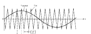
switches are turned off and on. The control signal, vcontrol, is used to modulate the switch duty ratio and has a frequency f 1 . This is the fundamental frequency of the inverter voltage output. Since the output of the inverter is affected by the switching frequency it will contain harmonics at the switching frequency. The duty cycle of the one of the inverter switches is called the amplitude modulation ratio, ma . [3]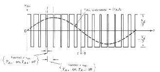
![]()
![]()
V control m
V
tri
where, Vcontrol is the peak amplitude of the control signal
f s![]()
![]()
m
f 1
IJSER © 2014 http://www.ijser.org
International Journal of Scientific & Engineering Research, Volume 5, Issue 7, July-2014 56
ISSN 2229-5518
vcontrol > vtri vcontrol < vtri![]()
Ta_pos is on, vA
![]()
Ta_neg is on, vA
Vd![]()
2
−Vd
![]()
2
This is usually not desired in most inverter applications.
Take for example if the inverter output frequency was going to be 60 Hz and mf = 15, then the triangle-wave frequency should be exactly 15 * 60 = 900 Hz.
When mf is large (> 21) the amplitudes of sub harmonics due to asynchronous between the triangle wave and the control signal are small. Therefore as long as mf is large the triangle-wave does not need to be proportional to the
In figure 8 the switches Ta+ and Ta- are controlled based on
the comparison of vcontrol and vtri (See equation 3). The two switches are never off at the same time which results in the output voltage fluctuating between +/- Vd /2. Figure 8 shows the fundamental frequency component (dotted line) for mf =
15 and ma = 0.8.
The harmonic spectrum of va under the conditions shown in figure 7 and 8 are shown in figure 9. This plot shows the peak amplitude of the fundamental frequency component.
desired inverter frequency. This is called asynchronous
PWM. [3]
D. Square-Wave Switching Scheme
A full-wave inverter can also be setup to be a square-wave inverter very easily. Once the PWM method is known, all the one needs to do to operate the inverter with a square- wave switching scheme is turn one switch on and the other off, back and forth, with a duty cycle of 0.5. The output voltage is limited to the input dc voltage given by equation 4. [1]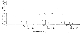
4![]()
![]()
V o ⋅V d
π
A good switching frequency and frequency-modulation ratio, mf, is usually considered to be better higher than lower. This is due to the fact that it is easier to filter out the harmonics at higher frequencies. The major draw back with is switching losses in the inverter switches increase proportionally with the switching frequency f s . In many inverter applications the switching frequency is taken to be either less than 6 kHz or greater than 20 kHz, which is out of the audible range. If for some reason the best switching frequency turns out to be between these two it is often outweighed with the advantages of having it over 20 kHz. Take for example an inverter that is going to operate around
60 hz, the frequency-modulation ratio mf would likely be 9 or less. The relationship between the triangular-waveform signal and the control voltage signal is determined by how big mf is.
When mf is small it is thought of as synchronous PWM.
The value of mf should be an integer so that it stays proportional to the desired inverter frequency. When the control signal is not synchronous, sub harmonics will occur.
E. Push-Pull Inverters
Figure 10 shows a push-pull inverter, it requires a center-tap transformer. If we assume the output current flows continuously then the switch T1 is on and T2 is off. Now, T1 will conduct for a positive value of io , and D1 would conduct for a negative value of io . This means that
the direction of io does not matter then, the output voltage is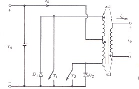
simply vo =Vd /n. In this equation n is the number of turns on the transformer between the primary-half and the secondary winding. The other state of the inverter is when T2 is on and T1 is off, the output voltage is now the same as before except it is negative. A push-pull inverter can be operated in either the pulse width modulation switching scheme or the square- wave switching scheme. The outputs are the same as before shown in figure 5.
IJSER © 2014 http://www.ijser.org
International Journal of Scientific & Engineering Research, Volume 5, Issue 7, July-2014 57
ISSN 2229-5518
Vd![]()
![]()
Vo ma⋅ n
V
where
V
ma <= to 1.0
would require lots of hardware including 12 switches for the three inverters used.
It is much more common to use a setup shown in figure 11. This setup consists of three legs, one for each phase. Each
d 4 d![]()
![]()
![]()
< V < ⋅
where m
leg is basically setup in the same way as the one-leg inverter
n o π
n![]()
VT 2⋅Vd![]()
IT io
a > 1.0
described above. In three phase inverters pulse-width
modulations is used in the same way as it is before except
that it much be used with each of the three phases. When generating power to three different phases one must make sure that each phase is equal, meaning that it is balanced. To ensure this the same triangle voltage waveform is compared with three sinusoidal control voltages that are 120 degrees
The above equation 5 and 6 show the push-pull inverter,
from figure 10, output voltage. One of the main advantages
of the push-pull inverter is that it is more efficient for low- voltage input sources, such as a battery. The reason for this is that the voltage drop across more than one switch in series would result in a significant reduction in energy efficiency. Also, the control drives for the two switches have a common ground. It is hard to avoid the dc saturation of the transformer in a push-pull inverter. The output current from the secondary current of the transformer is slowly varying current at the fundamental output frequency. This is usually assumed to be a constant during a switching interval. When the transistors are switched the current shifts from one half to the other half of the primary winding. This required very good magnetic coupling between these two half-windings in order to reduce the energy associated with the leakage inductance of the two primary windings. The energy will then be dissipated in the switches or in other circuits used to dissipate and help the switches. It is important that the current in the windings has a place to go when the switches are switched.
When the push-pull inverter is used in pulse-width-
modulation switching scheme for producing a output sinusoidal output, the transformer must be designed for the fundamental frequency that the inverter will be running at. That is, the number of turns will be high compared to a transformer designed to operate at the switching frequency in a switch-mode dc power supply. This will result in a high transformer leakage inductance that is proportional to the square of the number of turns. These constraints make it hard to use a push-pull inverter for switching frequencies of higher than 1kHz. [2]
IV. THREE PHASE INVERTERS
Many applications that require an inverter use three- phase power. Two main examples are an ac-motor drive and uninterruptible power supplies. One option for a “three-phase” inverter is to use three separate single phase inverters but vary their output by 120 degrees. This setup
out of phase.
The Harmonics in the output are only of concern in the
line-to-line voltages. The harmonics in the output of any one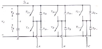
of the legs are identical to the harmonics in Va . Only the odd harmonics exist as sidebands, centered around mf and its multiples, provided, mf is odd. Only considering the harmonic of mf, the phase difference will be equivalent to zero if mf is odd and a multiple of 3. As a consequence, the harmonic at mf is suppressed in the line-to-line voltage vab. The same argument applies in the suppression of harmonics at the odd multiples of mf, if mf is chosen to be an odd multiple of 3.
Therefore, some of the dominant harmonics in the one-leg inverter can be eliminated from the line-to-line voltage of a three-phase inverter. PWM considerations are summarized below:
For low values of mf, to eliminate the even harmonics, a synchronized PWM should be used and
mf should be an odd integer. Moreover, mf should be a
multiple of 3 to cancel out the most dominant harmonics in the line-line voltage. Moreover, the slopes of Vcontrol and Vtri should be of the opposite polarity at the coincident zero crossings.
During over modulation (ma > 1.0), regardless of the value
of mf, the conditions pertinent to a small mf should be observed. [1]
IJSER © 2014 http://www.ijser.org
International Journal of Scientific & Engineering Research, Volume 5, Issue 7, July-2014 58
ISSN 2229-5518
V. POWER QUALITY
Power quality was a critical part of power system analysis. Power quality refers to the Total Harmonic Distortion (THD) as well as the presence of transients. To determine how inverters impact power quality, special monitoring equipment called the BMI Dual Node was used to measure the power quality on a sample system. The system used for measurement was a 20-KW photovoltaic array at Calvin College. It is a grid tied 3-phase system that uses two 10-KW Xantrex inverters.
A. Assumptions
It was assumed that the operating state of the inverters is typical for the selected three day window in which it was observed. This was a reasonable assumption since variations in the system over time will be minimal. Another assumption which was made was that the inverters would not be producing power during the night. This was a reasonable assumption, since the photovoltaic modules are by definition energized by the presence of sunlight.
B. Analysis
The single phase voltage was measured for this test, since the current could not be attained without actually interrupting the building power supply. The voltage measurements were taken from a breaker located adjacent to the photovoltaic system electrical panel interconnection points. The following is a graph of what was observed during standard operation. The peaks were during the day when the photovoltaic system was active, and the valleys were during the night when the photovoltaic system was not operational.
with potential that it will be raised to 9%). The spike near the end of this plot is due to the monitoring device being
removed from the power circuit. This means that the photovoltaic system did not detrimentally impact the power quality of the Interpretive Center over the observed time period. Continued monitoring of the building will be necessary to verify these results and validate the assumption that there will be little variation over time.
It was also important to note that the power quality
in terms of transients will not be adversely affected by the
disconnection of transformers during non production hours (over night). This was because the inverters are not producing at the time of disconnection and they are not under load. In discussing this issue with power systems expert Paulo Ribeiro, he said that he agreed that the automated shutdown of the transformers during the night was a terrific idea and would not introduce any big transients or harmonics due to the size of the transformers relative to the grid size.
C. Conclusion
In conclusion it can be stated, that the on-site source of power represented by the photovoltaic system will not detrimentally impact the building power quality. This was important since the building has a laboratory located in it, along with a number of computer workstations which could be adversely affected by significant voltage fluctuations.
Inverters by their nature are going to produce harmonics that are not wanted. This must be considered when designing an inverter. Xantrex makes a good inverter, as shown above, that can be tied into a grid and used without producing unwanted transients and harmonics.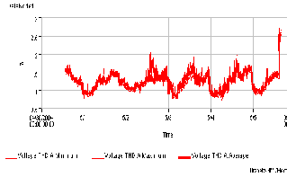
A. The System
VI. INVERTER SYSTEM DESIGN
From this graph we can see that during the daylight hours, harmonic distortion of the system did not go over 2.1
%, it should be noted that up to 5% THD is acceptable for
IEEE power requirements (this is currently up for revision,
Calvin College recently installed a 20-KW photovoltaic solar array as mentioned earlier. This system was going to be installed on top of a new building being built, the Interpretive Center at Calvin College.
The inverters were required to be grid connected and to provide some means of monitoring the production of the photovoltaic system in both kW-hr and peak kW for instrumentation purposes. I was port of a design team that was in charge of selecting the inverter and associated balance of system components. The layout and configuration of the inverters and the balance of system components (AC/DC disconnects, fuses, and wiring) was specified by the design team according to manufacturer requirements. The inverters were the part of the photovoltaic system that converted the electrical DC voltage from the photovoltaic modules, to AC voltage for use in the
IJSER © 2014 http://www.ijser.org
International Journal of Scientific & Engineering Research, Volume 5, Issue 7, July-2014 59
ISSN 2229-5518
building and rest of the campus grid. The Balance of System components included AC/DC disconnects, fuses, combiner
boxes, and transformers. Since these were specific to the inverter which was selected, these are derivatives of the inverter selection.
B. Design Criteria and Requirements
The inverters were required to be connected to the power system of the Interpretive Center, and to provide power to offset the building load. The inverters and their isolation transformers must be installed on the outside of the building, to minimize the cooling load of the building. The electrical power must be brought into the building in 3- Phase 208 VAC configuration. These inverters must be directly connected to the building electrical distribution panel. All photovoltaic components must be grounded continuously and terminated to the building ground at the electrical distribution panel.
C. Alternative Solutions
The different solutions for the inverters which were explored were compiled before the final determination had been made as to the voltage that the inverters would have to interface with the building.
Model | Trace SW Series (SW- 5548) |
Unit Cost | $3,196 |
Voltage Input | 48 VDC |
Power Rating | 5500 Watts |
# Units Required | 4 |
Voltage Output | 120 V 1-Phase |
Comm. Interface | RJ11-Serial Port |
Warranty | 5 Years |
Model | Outback Powre (FX2548) |
Unit Cost | $2,245 |
Voltage Input | 48 VDC |
Power Rating | 2,500 Watts |
# Units Required | 8 |
Voltage Output | 120 V 1-Phase |
Comm. Interface | RJ45 |
Warranty | 2 Years |
These options contained the primary inverters that are used for grid-tied photovoltaic systems. It was for this reason that they were investigated. Historically photovoltaic systems have been utilized mainly in standalone applications; as a result there were many more inverters available for small scale off-grid applications [5,6].
D. Analysis of Alternatives
The different alternatives which were listed above were rated as to their capability to meet a number of criteria, including costs, software interface, voltage, efficiency, PV module compatibility and warranty. The three inverters which were not 3-Phase capable were ignored as viable solutions because of the requirement to interface directly with the building power system.
E. Decision
The decision was made to use two Trace PV Series
10208 10kW inverters. We required two of these inverters, one for each side of the roof. This allowed us to monitor each roof separately since the two systems were electrically isolated from each other.
F. Test and Integration
Once the inverters and the entire photovoltaic system had been installed, (including the inverters and the balance of system components) the system was inspected by the city of Grand Rapids electrical inspector. Upon completion of this inspection a Grid-Interconnect study was completed for Consumers Energy. Upon approval by both of these agencies the photovoltaic system was brought online. Testing of the inverters prior to installation was accomplished by connecting them to a three-phase AC
IJSER © 2014 http://www.ijser.org
International Journal of Scientific & Engineering Research, Volume 5, Issue 7, July-2014 60
ISSN 2229-5518
source, and reading in the ac parameters. Detection of DC parameters was not possible since a large DC source was not available.
G. Implementation
The photovoltaic manufacturer provided a package including all of the balance of system components. Specifics regarding the wire size and conduit locations were determined and provided to the Physical Plant Department and the Wolverine Construction/Buist Electrical Contractors by way of the Large-Scale Photovoltaic Demonstration Project Drawing Set. Since Uni-Solar utilized a new MC Connect termination on their photovoltaic modules, it was decided by Don Winkle the Physical Plant Electrician that these same connectors should be used throughout the system.
VII. CONCLUSION
Inverters are a practical device and are a useful piece of equipment for many different applications. Anyone who wants to run a laptop or other electronic device within a car or RV an inverter is required. Inverter types can be categorized by output waveform, switch type, switching technology and frequency. In order to go from a constant DC voltage to an AC the input DC voltage is put through an oscillating circuit which creates the output AC. The output of the inverter can be a square wave, or a sine wave.
VIII. REFERENCES
[1] Ned Mohan, Tore M. Undeland, William P. Robbins Power Electronics: Converters, Applications, and Design. 1989. John Wiley & Sons, Inc.
[2] McGraw-Hill Companies, Inc. Principles and Applications of
Engineering, Thomas Casson, 2000.
[3] Mahdi Mozaffari Legha, Moein khosravi, Mohammad Hossein Armand, Mahdiyeh Azh,, “Optimization of Location and Capacity DGs Using HPSO Approach Case Study on the Electrical Distribution Network of north Kerman Province”, Middle-East Journal of Scientific Research, pp. 461-465, 2013.
[4] Mahdi Mozaffari Legha, Houman Gadari1,, “Technical and Economical Evaluation of Solar Plant for Electricity Supply Anar City Residential Customers”, Middle-East Journal of Scientific Research, pp.
455-460, 2013.
[5] Mahdi Mozaffari Legha, "Determination of exhaustion and junction of in distribution network and its loss maximum, due to geographical condition", MS.c Thesis; Islamic Azad University, Saveh Branch, Markazi Province, Iran; pp. 1-300, Aug 2011. [7] N. Medina, M.M. Qi, L. Butler-Purry, K.L. A Three Phase Load Flow Algorithm for Shipboard Power Systems (Sps), 2003.
[6] Narain G. Hingorani, Laszlo Gyugyi. Understanding Facts. The
Institute of Electrical and Electronics Engineers, Inc. New York, 1999.
[7] Mahdi Mozaffari Legha,; ”Optimal Conductor Selection of Radial
Distribution Networks Using GA Method” CIRED Regional – Iran,
Tehran, 13-14 Jan 2013; Paper No: 12-F-500-0320.
[8] Mahdi Mozaffari Legha, Marjan Tavakoli, Farzaneh Ostovar, Milad Askarihashemabadi, “Capacitor Placement in Radial Distribution System for improve network efficiency Using Artificial Bee Colony“, International Journal of Engineering Research and Application, Vol. 3, Issue 6, Nov-Dec 2013, pp.01-05
[9] Web site Electrical Power Engineering Specialists, REPORTs, 2014. Available at: <http://www.drmozaffarilegha.com.com> [accessed
01.01.2014]
[10] B.M. Bird, K.G. King, D.A.G. Pedder Introduction to Power
Electronics. Wiley New York, NY, 1993.
[11] Xantrex Inverters. Datasheets and Inverter Specs. http://www.xantrex.com
[12] Sunny Boy Inverters. Datasheets and Inverter Specs. http://www.sma.com
[13] Mahdi Mozaffari Legha and et al, ’’A new hybrid particle swarm optimization approach for sizing and placement enhancement of distributed generation’’ IEEE Conference, 2155-5516; Pages 1277 - 1281. [14] Mahdi Mozaffari Legha,;”Optimal Conductor Selection of Radial Distribution Networks Using GA Method” CIRED Regional – Iran, Tehran, 13-14 Jan 2013; Paper No: 12-F-500-0320.
[15] Mahdi Mozaffari Legha Majid Gandomkar, “Reconfiguration of MV network for balancing and reducing losses to by CYMEDIST software in Khorramabad”, 16th Electric Power Distribution Conference (EPDC16), pp. 25-32, 2012.
[16] Nariain G. Hingorani, Laszlo Gyugyi. Understanding Facts Concepts and Technology of Flexible AC Transmission Systems. IEEE Press, Piscataway, NJ. 1995.
[17] Dong Dai, Xikui Ma, Bo Zhang, Chi K. Tse. Hopf bifurcation and chaos from torus breakdown in voltage-mode controlled DC drive systems. Chaos, Solitons & Fractals, 2009; 41 (2): 1027-1033.
[18] A. Pisano, E. Usai. Sliding mode control: A survey with applications in math. Mathematics and Computers in Simulation
2011;81 (5):954–979.
[19] H. S. Choi, Y. H. Park, Y. S. Cho and M. Lee, “Global Sliding Mode Control Iimproved Design for a Brushless DC Motor,” IEEE Control Systems Magazine, vol. 21, 2001, pp. 27-35.
[20] Alfayyoumi, M., 1998, Nonlinear dynamics and interactions in power electronic systems, MS Thesis, Department of Electrical and Computer Engineering, Virginia Polytechnic Institute and State University, Blacksburg, Virginia.
[21] Utkin V. I., "sliding mode in control and optimization", Springer – Verlag, Berlin, 1992.
[22] Kamel Ben Saad, Abdelaziz Sahbani and Mohamed Benrejeb "Sliding Mode Control and Fuzzy Sliding Mode Control for DC-DC Converters" www.intechopen.com; National engineering school of Tunis (ENIT), Tunis, Tunisia, 2013.
[23] A. Hadri-Hamida, S. Zerouali, A. Allag ; "Control and Local Stability Analysis of a DC-DC Converter Feeding Distributed Power Systems", University Mentouri-Constantine, 2012
IJSER © 2014 http://www.ijser.org