
International Journal of Scientific & Engineering Research, Volume 4, Issue 1, January-2013
ISSN 2229-5518
An Innovative Method to study the effect of different Magnetic material (i.e. Dia, Para, Ferro) on the dynamics of an Oscillating Magnet using Tracker v1.7.5.
Centre for Development of Physics Education, University of Rajasthan, Jaipur 302004
Rajasthan, INDIA
Abstract— In this geometry, anharmonic oscillator has been modified by introducing a permanent magnet clamped vertically; oscillating above different magnetic material plates (i.e. diamagnetic, paramagnetic, and ferromagnetic) placed horizontally. The study on dynamics of an oscillating magnet like (1) measurement of displacement as a function of time, (2) kinetic energy of the system is done by video analysis using Tracker v1.7.5.
Index Terms— Experimental Physics, Anharmonic Oscillator, Tracker v1.7.5., Damping, Magnetic material properties: diamagnetic, paramagnetic and ferromagnetic materials.
—————————— • ——————————
HIS paper describes very simple modifications in the ge- ometry of a compound pendulum, which can accomplish
the basic features of the anharmonic oscillator. The effect of gravity is nullified by choosing the centre of mass of the sys- tem to be the point of suspension. A permanent cylindrical magnet is clamped vertically such that the oscillating magnet faces above magnetic material plates (i.e. diamagnetic, para- magnetic, ferromagnetic) setup. For every magnetic material, a video was recorded using fixed camera. The innovative meth- od is the video analysis done with point mass technique using Tracker v1.7.5.
The compound pendulum consists of an aluminum rod of length 85 cm and diameter 1.2 cm. It is pivoted on a stand on two points 30 cm from the top. Two masses of about 700 gm each are clamped on the top as well bottom of the rod. The position of the masses enables one to change the time period of the compound pendulum from 1 sec to 10 sec (in principle up to infinity). The cylindrical magnet is clamped to the oscil- lator rod in vertical geometry such that the oscillating magnet faces above magnetic material plates (i.e. diamagnetic, para- magnetic, and ferromagnetic) with horizontal setup. One
————————————————
# Er. Ashish Upadhyay is currently pursuing Master’s of Technology in Engineering Physcis from Centre for Development of Physics Education, University of Rajasthan, Jaipur-302004 Rajasthan, INDIA
He graduated with Bachelor of Technology in Electronics & Communication
Engineering from Rajasthan Technical University, Kota-324010
pointer is attached to the oscillator for the measurement of amplitude of oscillator on the circular scale of radius of curva- ture about 60 cm, attached to the stand.
Fig. 1. Anharmonic oscillator setup of CDPE (Centre for Development of
Physics Education, University of Rajasthan, Jaipur)
The term magnet is typically reserved for objects that produce their own persistent magnetic field even in the absence of an applied magnetic field. Most materials, however, produce a magnetic field in response to an applied magnetic field; a phe- nomenon known as magnetism.
Rajasthan, INDIA. E-mail: ashishupadhyay.in@gmail.com
IJSER © 2013
International Journal of Scientific & Engineering Research, Volume 4, Issue 1, January-2013
ISSN 2229-5518
There are several forms of magnetic behavior in different ma- terials. Here, as a diamagnetic material copper is used; tanta- lum is used as a paramagnetic material while iron is used as a ferromagnetic material.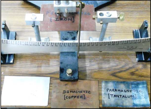
Fig. 2. Magnetic material plates
(diamagnetic, paramagnetic, and ferromagnetic)
Tracker is a video analysis package built on the Open Source Physics (OSP) Java framework. Features include object track- ing with position, velocity and acceleration overlays and graphs, special effect filters, multiple reference frames, calibra- tion points and line profiles for analysis of spectra and inter- ference patterns.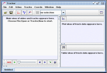
Fig. 3. User interface of Tracker v1.7.5.
5.1 Measurement of displacement as a function of time
The displacement of oscillator from its equilibrium position by application of external force was recorded for all the three magnetic plates. The video analysis was done by Tracker which gives the desired result for the measurement of dis- placement of oscillating magnet as a function of time.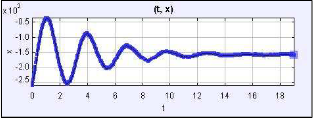
Fig. 4. Shows the oscillating magnet’s displacement as a function of time for the diamagnetic material plate (Copper) using Tracker v1.7.5.
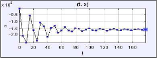
Fig. 5. Shows the oscillating magnet’s displacement as a function of time for the paramagnetic material plate (Tantalum) using Tracker v1.7.5.
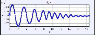
Fig. 6. Shows the oscillating magnet’s displacement as a function of time for the ferromagnetic material plate (Iron) using Tracker v1.7.5.
5.1 Kinetic energy of the system
For the same system the displacement of oscillator from its equilibrium position by application of external force was rec- orded for all the three magnetic plates. The video analysis was done by Tracker which gives the desired measurement of the kinetic energy as a function of time of the whole system.
IJSER © 2013 http://www.ijser.org
International Journal of Scientific & Engineering Research, Volume 4, Issue 1, January-2013
ISSN 2229-5518
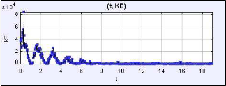
Fig. 7. Shows the system’s kinetic energy as a function of time for the diamagnetic material plate (Copper) using Tracker v1.7.5.
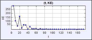
Fig. 8. Shows the system’s kinetic energy as a function of time for the paramagnetic material plate (Tantalum) using Tracker v1.7.5.
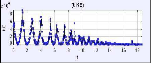
Fig. 9. Shows the system’s kinetic energy as a function of time for the ferromagnetic material plate (Iron) using Tracker v1.7.5.
The Tracker software has clearly analyzed the various parame- ters of the different magnetic material plates.
The diamagnetic make a weak contribution to the material’s response to a magnetic field as traced in fig.4; and its kinetic energy of the system also remains low as in fig.7.
We know that, paramagnetic materials have a small, positive
susceptibility to magnetic fields. These materials are slightly attracted by a magnetic field and the material does not retain the magnetic properties when the external field is removed. Paramagnetic properties are due to the presence of some un- paired electrons, and from the realignment of the electron paths caused by the external magnetic field; this can be clearly visualized in fig.5. As in fig.8 kinetic energy of the system gradually takes a long time as compared to other materials.
Ferromagnetic material possesses strong magnetic behavior.
These materials can be magnetized by an external magnetic field and remain magnetized after the external field is re- moved. The magnetization property can be clearly seen in fig.6 with damped oscillation; while the kinetic energy of the sys- tem remains initially high due to its magnetizing property but rapidly slows down the oscillating magnet and the system as in fig.9.
Using this apparatus, a number of interesting measurements
can be demonstrated and performed on the anharmonic oscil- lator.
I am thankful to Professor Y.K. Vijay for the valuable guidance and supervision in the whole project. The suggestions and assistance provided by him, to improve the apparatus at CDPE workshop made this project successful. His innovative idea of using the Tracker in different physics laboratory exper- iments encouraged me in performing this work.
[1] Yogesh Kumar Vijay (July-Sep 1993), Laboratory Experiments on An- harmonic Osciilator, Physics Education.
[2] B. Saraf et al., Physics Through Experiments, Vol. II, Mechanical Sys- tems, Vikas Publications.
IJSER © 2013 http://www.ijser.org