International Journal of Scientific & Engineering Research, Volume 5, Issue 9, September-2014 138
ISSN 2229-5518
An Experimental Study on Improving the Thermal
Storage of ICWS
Suha Abdulelah Mohammed
Department of Mechanical Engineering, University of Technology, Baghdad, Iraq
Email: shwasuha@yahoo.com
ABSTRACT-The integrated collector water storage (ICWS) systems are simple type solar water heaters that can be used for the supply of hot water for domestic purposes. The present research is an experimental study on of a storage solar collector .This was done by modifications in the design by (sabah, 2005) . The design is simple and low cost compared with other solar water heaters. Giving a capacity of about (210 liter).The collector was tested during the period from February to July (2011), under Baghdad climatic condition. The experimental results show it is possible use to a storage solar collector for domestic hot water applications, where possible heating 210 liter of water to different temperatures depends on stratification phenomenon. It is noted that maximum temperature for 7 February is 51.5 °C and minimum temperature is
31 °C , while the average temperature is 37 ° when is initial temperature of water equals 15.9 °C , This means rise water
temperature of 22 °C
Keywords : integrated collector, Absorber surface, ICSSWH systems, solar collector, solar storage.
1 INTRODUCTION
olar water heaters are considered as the fastest develop ing technologies within the renewable energies field. A small solar water heater can be a practical and economic
means to supply hot water in a reliable way for many years in remote areas or in electricity lacking areas though they have abundance of sunlight. Commonly solar water heaters are classified into three groups (Rakesh, 2011)[2]: solar water heaters which operate by natural (free) convection, solar water heaters which operate by forced convection and the Integrated Collector-Storage Solar Water Heater (ICSSWH). Of all solar water heater designs, the simplest and least expensive design is (ICSSWH) because it does not contain any moving part and the solar collector and the storage tank constitute one unit. Therefore a lot of research has been done to find out the effect of some factors on its performance such as climate, operation conditions and location (Mejdi H. et al., 2005)[3] and (Smyth et al., 2006). Researches carried out in many parts of the world have, undoubtedly improved the performance of (ICSSWH) through making research on a variety of designs (rectangular, cylindrical, triangular, trapezoidal, etc). Among these designs is the one made by ( Mcveigh, 1977)[4]. It is a variable depth tank called a simple tank for collection and storage at the same time. This collector is characterized by absence of absorption plate because the water inside performs both processes of col- lection and storage. (Jose at el, 2002)[5] Studied the perfor- mance of a trapezoidal storage tank under varying weather European conditions (Portugal). He showed that the shape used helps to increase the thermal gradation in a solar storage tank. (Garnier at el, 2009)[6] Made an experimental and theo- retical study on finding out the best design for simply struc- tured low cost solar storage tank in the form of triangular box operating under varying weather conditions of Scotland. On the other hand, (Souliotis and Tripan, 2004)[7] made an exper- imental study on cylindrical tank with reflecting panels to im-
prove its performance. Another study was made by (Ihad- dadene et al, 2013)[8] on the effect of flow rate and inclination angle on the performance of a solar collector tank consisting of two parts, one for storing the solar energy and the other for storing it. (Joudi et al., 2004)[9] studied numerically the heat distribution in a prism shaped storage solar collector with right triangular cross section. (Ecevit et al, 1989)[10] and (Kaushik et al., 1994)[11] dealt with storage solar collector of triangular area and concluded that this design improves the performance of the collector and and increases the rate of heat transfer from the absorption panel to the water while (Mo- hamad, 1997)[12] made an experimental study on a storage solar system, using thermal diode to prevent reverse circula- tion at night. (David at el, 2001)[13] designed a storage solar tank in such a way as to be able to reduce heat escape at night. (Sabah, 2005)[14] made an experimental study on a prism shaped storage solar collector with right triangular cross sec- tion operating under varying weather conditions of Baghdad. The obtained show that it is possible to use this type of collec- tors to heat water for domestic use. The design has been im- proved by (Wissam H. A., 2008)[15]. He modified the design by reducing water volume in the collector, thus improving the thermal gradation (compared with that before improvement. From the above short survey, it can be seen that to improve the performance of solar water heater type ICSSWH requires making a design which contributes to improvement in the thermal performance in addition to finding a solution to the problem of thermal insulation in case the collector is used when sunlight is not available. Thus in this research an at- tempt is made to identify and examine a storage solar collector consisting of two parts, the first part is used for collecting while the second for storing. The results will be compared with those of (Sabah, 2005)[1] whose results have been chosen for comparison purposes because they were obtained in condi-
IJSER © 2014 http://www.ijser.org
International Journal of Scientific & Engineering Research, Volume 5, Issue 9, September-2014 139
ISSN 2229-5518
tions similar to those of Iraq.
2 THE MANUFACTURE OF THE SOLAR COLLECTOR
In order to make a successful and accurate experimental study using the proposed design, a solar collector was made accord- ing to the proposed design. It is a storage solar collector con- sisting of two parts the first is the heat collector and made in prism shaped with right triangular cross section. It is used to reduce water quantity in the collector (Wissam, 2008)[15]. The second part represents the heat storage part. Although it is part of the collector, it is always isolated. The photograph in Fig (1) and the diagram in Fig (2) show the general configura- tion of the solar collector used.
The solar collector used provide an inclination angle of (45º) from the horizon which is the optimum inclination angle for a collector as regards Baghdad in winter due south (Mehdi Ra- yahi, 1979)[16]. It was tested in the time period from the be- ginning of February until the end of July 2011 under different weather conditions of Baghdad. a proposed collector gives water output of 210 liters, the storage tank and the absorption plates were made of galvanized steel sheet with 1.25 mm thickness. The absorption plate was coated with dark non transparent black paint (produced by Iraqi Modern Paint Co). A 4 mm thick ordinary glass cover was fixed inside a frame with rubber silicone adhesive in addition to a special paste to prevent the leakage of warm air from the air space. The dis- tance between the glass cover and the absorption plates is kept at 2.5 cm because this distance gives optimum insulation for heat transfer by convection and radiation from the hot absorp- tion plate relative to the cold glass cover (Duffie and Beckman,
2006)[17].
The collector was provided with a tube to allow the hot water to flow out of the upper part and with another one to supply the lower part with water. In the current study use has been made of the thermal gradation phenomenon which takes place in the collector due to difference in density, resulting in the potential of heat storage in the well-insulated upper part of the collector and the potential of heat transfer from the hot part of the collector and the potential of adding another quan- tity to the cold part. This will improve the thermal gradation of the water, thus making the collector work with more effi- ciency in contrast to the collector in the first case in which heat loss becomes great after sunset or when there are clouds and in such a case the hot is not used. a storage solar collector was insulated at bottom and on the sides with 5 cm thick glass wool layer. The collector was covered with 3 mm thick wooden boards to protect the collector and the insulating material from weather effects as well as the wood acts as an additional insu- lator to reduce heat loss.
Ten thermocouples were fixed inside the solar collector to measure water temperature which was connected by using fine metallic wires. The heat storage tank into parts equal in height but varying in area depending on the inclination of the absorption surface as illustrated in Figure (2). The thermocou- ple point was fixed in the middle of each area to measure temperature average at that particular area. The thermocou- ples used were Copper Constant type and were connected to a
digital thermometer made by American Comark, through 20 point selector switch. The ambient temperature was measured with a mercury thermometer which was isolated from weather effects. Before the measurements were started, calibration of the instruments was made.
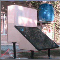
Figure 1: The storage solar collector used in the research
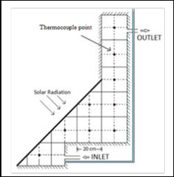
Figure 2: The diagram of solar collector used in the research
3 THEORETICAL ANALYSIS
Theoretical analysis involves calculating the system heat losses and the quantity of energy absorbed by and that stored in so- lar collector as well as the efficiency .The quantity of energy lost which takes place on all collector sides is calculated by the Equation:
QLoss = UL . Ap.�Tp − Ta � … … … … … (1)
The coefficient of the total loss (UL) is the sum of all coeffi-
cients of heat losses from the absorption plate which represent
the main part of heat losses called top losses and coefficient of
the heat losses which take place on all collector sides which are called edge losses. These losses are small compared with the top heat losses, therefore they are neglected. There are sev-
IJSER © 2014 http://www.ijser.org
International Journal of Scientific & Engineering Research, Volume 5, Issue 9, September-2014 140
ISSN 2229-5518
eral experimental relations to calculate the coefficient of top heat losses. The best experimental relation to calculate (U) was proposed by Akhtar and. Mullick, (2007)[18].
The efficiency of the solar collector is calculated by the follow- ing relation:
𝑄𝑢(𝑎𝑐𝑢.)
−1
⎡ ⎤
⎢ N 1 ⎥
𝜂 =
𝑄𝐴𝑏𝑠

… … … … (6)

Ut = ⎢
⎢�C T
�Tp

e + ⎥

− Ta � hw ⎥
4 PROCEDURE
� �
⎣ p (N + f) ⎦
⎡

2 2
The performance of the solar collector was examined under
various Baghdad weather conditions lying at latitude of 33o N
⎤ and longitude of 44o E. The experiments were carried out at

⎢ σ�Tp − Ta ��Tp − Ta �
+
… (2)
collector which incline by 45o from the horizon and oriented
−1 �2N + f − 1 + 0.133 ∈p � ⎥
to the south during winter and summer stating from February
⎢�∈p + 0.00591Nhw � + �
⎣ g
� − N⎥
⎦
to the end of July, 2011. Five experiments were conducted eve-
ry month on different days. The total number of experiments
f = �1 + 0.089hw − 0.116hw ∈p �(1 + 0.07866N)

100
e = �1.43 − �
p
C = 520(1 − 0.0051β2) for 0° < 𝛽 > 70°
The quantity of energy absorbed from the absorption plate
and transferred to the water is calculated from the following
equation:
QAbs. = Ib . Ap . Ft . �τg αp� … … … … . (3)
Ft = Fsh Fd
The (Ft) represents the effect of the total coefficient of shade
and dust on the quantity of sunlight received by the absorp-
tion plate whose value is equal to (0,98) (Wissam, 2008)[15] On
the other hand, the quantity (αpτg) represents the sum of mul-
tiplying the absorption of the absorption plate by the permea- bility of the glass cover. It varies with visual properties of the glass cover depending on the angle of the fall and the reflec- tion of the falling sunlight during the day. it was calculated for every hour, depending on the reference (Duffie and Beckman,
2006)[17] . The intensity of sunlight is estimated theoretically
(Sahib at el., 2010[19]). The actual heat energy stored in each solar collector is calculated as follows:
MCw (Tav − Ti )
conducted was more than thirty. The readings of the meas-
ured variables were recorded every hour. The variables were
the temperature of the water stored, the temperature of the
ambient air, the temperature of the of the absorption plate, the
temperature of the water entering and exiting the solar collec-
tor. The collector was examined without load, that is, without
drawing any water. The average of water temperature was
calculated. All experiments were started at 8.30 a.m. and end-
ed at 3.30 or 4.30 p.m., depending on the season the experi- ments were made. Before an experiment was made, the collec- tor was filled with water, the glass cover cleaned, the measur- ing device and thermocouples examined
5 RESULT AND DISCUSSION
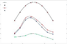
The experiments on the solar collector were conducted under various Baghdad weather conditions from February to the end of July, 2011. From these experiments and theoretical calcula- tions carried out on the solar system, the results of some ex- periments were selected to be represented as graph so that their performance can be assessed. Figure (3) show the varia- tion solar radiation intensity and the acquired and actual heat energy and ambient air temperature for collector during the day in February. Gradual increase in solar radiation intensity until it reaches it maximum at midday and then it starts to decrease gradually. Thus it gives a general outline of the be- havior of the useful energy, its value increases gradually until
midday, following solar radiation intensity but with differ-
Qu(acu.) =

t … … … … (4)
ence. This difference decides the efficiency of the collector. Furthermore, this figure show there is a close relationship be-
According to the classification of (Rakesh and Marc, 2011)[2],
the collector used was the thermally graded tank in which the gradation is clearly shown along its height from the point of entry to the point of exit because of density difference. The average of temperature for each collector is calculated by the following relation:
tween the energy acquired theoretically and the energy ob- tained in practice. This relationship gives a clear indication of the accuracy the equations used to calculate the quantity of solar radiation received by the absorption plate of each collec- tor.
Tav =

∑ Mn Tn
MTot
… … … … (5)
where, Mn.Tn is the mass of water and temperature in every part of the collector. Figure (2) illustrates this division.(MTot ) is total mass.
IJSER © 2014 http://www.ijser.org
International Journal of Scientific & Engineering Research, Volume 5, Issue 9, September-2014 141
ISSN 2229-5518
50
Temperature of air
45 Solar energy
Qth.
40 Qacu.
35
30
900
800
700
600
500
highest level almost at midday, depending on the intensity of sun radiation. Then it continues increasing until the end of the experiment but at decreasing level because of the gradual de- crease in sun radiation in the afternoon and increase in ther- mal losses. The highest water temperature inside collector during July was (55.5 °C).
25 400
20 300
15 200
60
July
June
10
5
6 8 10 12 14 16 18
Time (hr)
100
0
50 May
Apr. Mar.
40
Feb.
Figure 3: The variation of solar, actual and theoretical energy 30
with time for present collector. and collector. by researcher [1]
20
.
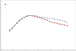
Of the important factors which determine collector efficiency and its use in the appropriate application is the average water temperature inside the collector. It can be defined from the
relation Tav = ∑ Mn Tn /MTot already referred to in equation (5).
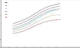
Figure (4) show the results of calculating the average water
temperature inside solar collector (for the period from Febru-
ary to July). It can be seen that the average water temperature
continued increasing until the end of the experiment. This
10
0
8 9 10 11 12 13 14 15 16 17 18
Time (hr)
Figure 4: The variation of water temperature with with hours
of the day for various months
40
Present Exp.
agrees with what sources have mentioned (Joudi, K.A., et al,
2004) and (Wissam, 2008) about hourly increase but they differ in terms of value. Undoubtedly this is due to difference in the quantity of water, heat losses and design method. The average water temperature reached 31 ºC and 55.5 ºC in February and June respectively for solar collector. The average water tem- perature of present storage collector was lower than collector by researcher [1] in all experiments conducted. This is logical and expected as collector by researcher [1] has less quantity of water by 40 liters. These results show important points the
35
30
25
20
15
10
5
Sabah [1]
first of which is that the solar collector operate in a correct way
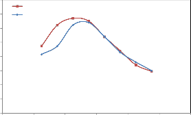
and the difference in the average temperature between the two designs is not great and can be justified or accepted by increas- ing the quantity of hot water by (23%) liters of the stored wa- ter. In addition, there is a quantity of water of 40 liters stored which can be used at night. It is at a suitable temperature of about 35 ºC. Figure (5) shows the variation in temperature average with hours of the day for the period from 8 o’ clock p.m until 6 o’ clock p.m. of the next day during February. Comparing our results with those obtained by researcher (1), it is found that after there is sharp drop in temperature of pre- sent collector, less drop in the collector used by researcher [1] who used two layers of glass panel.
This storage collector according to classification (Rakesh and Marc A., 2011) uses a tank which is graded thermally. This gradation is clearly shown along its height starting from the entry to the exit due to density difference. This gradation is responsible for transferring heat from the hot (upper) part of the collector and the addition of another new quantity of cold water. Figure (6) illustrate how the maximum and minimum water temperatures vary inside the collector. The temperature continues to increase as heating continues until it reaches its
5 10 15 20 25 30 35
Time (hr)
Figure 5: The variation of water temperature with time for present collector and collector by researcher [1]
60
Tmix
Tmin
50 Tair
40
30
20
10
0
6 8 10 12 14 16 18
Time (hr)
Figure 6: The variation of the mixumm and minmum water temperature
with time for present collector.
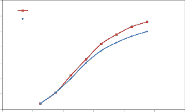
Figure (7) shows the effect of the present design with the insu- lated additional tank on the increase in the average tempera-
IJSER © 2014 http://www.ijser.org
International Journal of Scientific & Engineering Research, Volume 5, Issue 9, September-2014 142
ISSN 2229-5518
ture rise. When water is not drawn for storage collector by researcher [1], thermal gradation will decrease because of the reduction in falling sun radiation on one hand and increase in heat losses due to the increase in difference in temperature between water in the collector and ambient air, on the other hand. In present storage collector, when water is not drawn during the day, the collector insulated part will keep the hot water and continue heating the water in a better way.
70
60
50
40
30
20
present Exp. Sabah [1]
60 10
50
40
30
Tmix, present Exp. Tmix, Sabah [1] Tair
0
6 8 10 12 14 16 18
Time (hr)
Figure 8: The variation of stored energy with time for present collector and researcher [1]
80
20 present Exp.
70 Sabah [1]
10
60
0 50
6 8 10 12 14 16 18
Time (hr) 40
Figure 7: maximum water temperature with time for present collector
30
and collector by researcher [1]
20
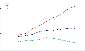
Among the main and important functions of storage solar col- lectors is the storage of solar energy. The function of the aver- age of water temperature and water volume in the collector with other variables kept constant. Therefore the quantity of energy stored and accumulated in the collector is always in continuous increase during the experiment period depending on the increase in the difference in temperature between tem- perature during the day and the initial temperature. The stored energy for every volume unit is calculated by relation (Ihaddadene R. et al, 2013).
Qs = ρC(Tav. − Ti ) … … … … (7)
Figure (8) shows the variation of this energy with daylight for
present storage collector and storage collector by [1]. It can be
seen that the total stored energy for every volume unit in Feb-
ruary is (58 MJ/m3) for present collector and (50 MJ/m3) for
collector by [1].
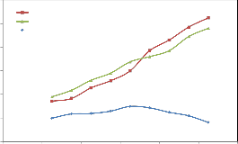
Figure (9) shows how the hourly efficiency of solar collectors undergo variation with daylight where there is no load on them (no water is drawn). It can be seen that the practical col- lector efficiency is low during early daylight because the fall- ing solar radiation is small at that time and then it starts in- creasing until almost midday due to the rise in water tempera- ture in the collector as well as the heat loss is little then. Con- sequently the efficiency is decreased as a result of reduction in the accumulated thermal energy accompanied by increase in heat losses.
10
0
6 8 10 12 14 16 18
Time (hr)
Figure 9: Variation in hourly efficiency for present collector and collector by researcher [1]
6 CONCLUSION
Results obtained from experiments conducted on solar collec- tor show that it is possible that a low cost solar collector with simple design can supply warm water at a suitable tempera- ture and thus saves in electrical energy compared with tradi- tional storage solar collector. the storage solar collector by re- searcher [1], though it gives good results considering Baghdad weather, its average temperature will reduce as a result of great heat losses when water is not drawn in daytime. Fur- thermore, it cannot be used during the night. The new design overcomes these drawbacks by using an additional insulated tank as a part of the collector, in which warm water is kept due to density difference. Results have shown also that the proposed design gives average temperature in February and June is (35°C) and (55°C) respectively and it provides 40 liters at a suitable temperature for domestic use after sunset while collector by researcher [1] cannot keep the water warm after sunset.
IJSER © 2014 http://www.ijser.org
International Journal of Scientific & Engineering Research, Volume 5, Issue 9, September-2014 143
ISSN 2229-5518
7 REFERENCES
[1] Sabah T., “Experimental and Theoretical Study on Solar Collector Storage Pyramidal Right Triangular Cross section Area” Engineering & Technology Journal 24(2005) 329-343..
[2] Rakesh and Marc A., “Integrated Collector-storage Solar Water Heater with
Extended Storage Unit, Applied Thermal Engineering, 31 (2011) 348-354.
[3] Mejdi et al., “Performance of a Solar Storage Collector” Desalination2005,
183, 167–172,
[4] Smyth, M., Eames, P.C., Norton,B. “Integrated Collector Storage Solar
Water Heaters” Renewable and Sustainable Energy Reviews 10 2006, 503–
538.
[5] Mcveigh, J. C., “Sun Power: An Introduction To The Applications Of Solar
Energy” Pergamon Press Inc., Oxford, 1977.
[6] Jose M.S. Cruz at el., “Thermal Performance of a Trapezoidal-shaped Solar
Collector/energy store” Applied Energy 73 2002, 195–212.
[7] Garnier, C., Currie, J. Muneer, T. “Integrated Collector Storage Solar Water
Heater temperature stratification” Applied Energy 86 2009, 1465–1469.
[8] Tripan, Y., Souliotis, M. “ICS Solar Systems with Horizontal (E–W) and
Vertical (N–S) Cylindrical Water Storage Tank” Renewable Energy 2004,
29 .73–96.
[9] Ihaddadene R. et al., “The Effects of Volumetric Flow Rate and Inclination Angle on the Performance of a Solar Thermal Collector” Energy Conversion and Management (2013). Available at http://www.sciencedirect.com/science/article/pii/S0196890413006122
[10] Joudi, K.A., et al., , “Computational Model for a Prism shaped Storage Solar Collector with a Right Triangular Cross section” Energy Conversion and Management 45 (2004) 391–409.
[11] Ecevit,A., A.M., Al-Shariah, Apaydin, E.D., “Triangular Built-in Storage
Solar Water Heater”, Solar Energy 42 (1989) 253-265.
[12] Kaushik, S.C., et al., “Transient Analysis of a Triangular Built-in-storage Solar Water Heater under Winter Conditions, Heat Recovery Systems and CHP, 14 (1994) 337-341.
[13] Mohamad,A. A. “Integrated Solar Collector–Storage Tank System with
Thermal Diode” Solar Energy Vol. 61, No. 3, pp. 211–218, 1997
[14] David Faiman at el., “Reducing the Heat Loss at Night from Solar Water Heaters of the Integrated Collector–Storage Variety” Solar Energy Vol. 71, No. 2, pp. 87–93, 2001
[15] Wisam H. A., 2008 “A Simple Design Solar Water Heater” Al- Taqani Journal, 21, 27-38.
[16] Mehdi Rayahi "estimate the amount of solar radiation on surfaces at differ- ent directions in Iraq during the clear days " Master Thesis, college of Sci- ence, University of Mustansiriya, Iraq, 1979.
[17] John A. Duffie, William A. Beckman, “Solar Engineering of Thermal Pro- cesses” John Wiley & Sons, Inc. Third Edition. 2006.
[18] Akhtar, N., Mullick, S.C. “Computation of glass-cover temperatures and top heat loss coefficient of flat-plate solar collectors with double glazing” Ener- gy (2007), 32, 1067–1074
[19] Sahib N. Abdul-Wahid at el., “Estimation and Comparison of Diffuse Solar Radiation over Iraq” Kufa Juornal of Engineering, Volume, 1, Number, 2, (2010) 153-174.
IJSER © 2014 http://www.ijser.org