International Journal of Scientific & Engineering Research, Volume 4, Issue 12, December-2013
ISSN 2229-5518
1576
An Android Phone Thermometer for
biomedical temperature Measurement
Shivaraman Ilango
Abstract- This paper demonstrates the design and implementation of a portable and handy android phone thermometer that is used for continuous measurement of body temperature from infants to elderly people. It initiates an immediate alarm when the temperature becomes abnormal cases like fever, under heating and high temperature over a prolonged period of time. This system is integrated with an android smart phone which helps in monitoring the temperature conditions of a person even from remote places. This robust invention can be interfaced even with an PC or laptop for convenient use by doctors.
Index terms- Android Phone, Bluetooth, Micro controllers, Memory, Temperature sensor, Temperature monitoring, Thermometer
1. INTRODUCTION
well-known condition in the medical field where kids go under convulsion due to high fever or due
IJSEto sudden risRe of temperature. Even though this
Android Smart Phones provide solution for
various problems in the form of android applications. So in this paper a biomedical temperature monitoring system is designed to monitor the body temperature, thus providing various notifications. This way, parents and doctors are guaranteed to have full data readings all the time without being hindered by staying with the patients. The proposed system is user friendly provide low cost, and designed with reliability and accuracy in mind.
Elevated body temperatures are considered one of the most common symptoms of diseases. Continues monitoring of such changing parameter is challenging considering the inconvenience of repeated measurement of an individual's body temperature, especially when the person may seem doing well-. Such a system is more needed for children and disabled patients where there body temperature indicates important information about their conditions, and they may not be able to communicate such information to their parents or care taker. Our system targets the category from infants to elderly persons. Their condition requires a lot of monitoring and their body temperature is a
critical sign of their wellbeing. Febrile seizure is a
condition may not be a life threatening, but it is the hardest situation for any parents or even health care provider to see a child in such condition. Early intervention and prediction of when the patient may go into such state is the only way this situation can be prevented. Such prediction enables parents or care giver to administrate fever control medication to prevent the high fever that may cause the seizure. In addition to the proposed usage for vulnerable person with certain conditions the system is also suitable for normal children during night time or during the day when parents are at work and the kids are in day care where parents can monitor their children health through a distance. The leverage of wireless technology through cell phone capability makes this system viable and cost effective. This proposed temperature monitoring system differs from the commercial products by its programmability and ability to change temperature limits and monitor it remotely. No commercial thermometer that has all the functionality proposed by our design.
2. SYSTEM ARCHITECTURE
The system shall always check for three hazardous conditions which are maximum temperature,
IJSER © 2013 http://www.ijser.org
International Journal of Scientific & Engineering Research, Volume 4, Issue 12, December-2013
ISSN 2229-5518
1577
minimum temperature, and maximum temperature change over a specific period of time. Maximum temperature mainly monitors fevers which are the main interest in human body temperature. The system also monitors low body temperature as babies may fall into such situation. Another important aspect is changes of temperature over certain period of time, ∆T, to detect abnormal biological activities. Normally, the human body temperature is in the range of 36°C to
37 °C while temperatures up to 37.5 °C are considered higher temperature. Until this limit the condition is not critical, however, since we are considering babies, elevated temperatures start from 37.5 °C up to 38°C where it is considered fever starting from 38 °C up to 38.5 °C. A Lethal temperature of 39°C and above where medical treatment is a must or the patient, especially a baby, will be in danger.
readings. However, more sensors can be used at different body location and different weights can be assigned to them to get accurate readings. The Bluetooth module used is CC2540 with MSP430 processor. The microcontroller used here is Cortex- M ARM microcontroller.
3. SOFTWARE IMPLEMENTATION
3.1 INTITALIZATION PHASE
Upon being turned ON, the system first goes through initialization phase where the pins are defined as inputs and outputs for digital lOs, SCI, SPI, and parallel communications. The connection with the Bluetooth module was defined to be a serial communication with baud rates are defined to be of 57600 bps using the microcontroller's main
Rx and Tx. Next, the LCD is set up using the
Liquid Crystal library by setting the pins mentioned in Table 1 to operate the LCD screen in the 4- bit control mode. Next, the LCD was initialized by defining its display capacity of 2 rows and 16 columns followed by displaying a welcoming message to the user. Following is the setup of the microSD card. For our system and for
convenience, pin 10 was defined as a digital output
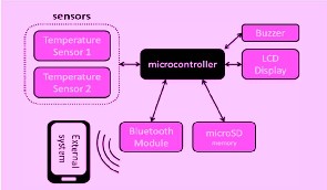
Fig 1 System Architecture showing the main component of the proposed embedded system
The temperature sensor used here is DS18B20, which is a one wire temperature sensor. This prototype can handle up to 10 sensors. The reason for using this sensor is that it has high precision rate and allows a huge number of sensors to be used on one data bus. The output voltage is in the form of Celsius and can be converted to Fahrenheit using the below functions.
Temp_C = 100 X Vinput – 50 (1) Temp_F = Temp_C x 9/5 + 32 (2)
Our prototype has two temperature sensors to measure the body temperature. The measurements
of those two sensors are then averaged to get better
pin and connected as the chip select pin. After that, the software initializes tries the microSD card using SD card library and check if it is available. The memory card's state is held in a flag as will be used for future operation processes. The final setup is defining the digital pin connected to the buzzer and digital output. The analog pins connected to the temperature sensors don't require to be initialized for reading.
3.2 COMMAND PHASE
The first operation phase in the grand loop is the command phase where the system checks if there are any incoming commands via Bluetooth or any serial communication interface. If there are no incoming bytes, then this phase is skipped and the
IJSER © 2013 http://www.ijser.org
International Journal of Scientific & Engineering Research, Volume 4, Issue 12, December-2013
ISSN 2229-5518
1578
code proceeds to the next phase with the default settings. However, if incoming bytes were detected, the software reads the whole incoming data string. Since this is a standard serial communication, the data is expected to end with a carriage return (CR) byte followed by a line feed (LF) byte. The software keeps reading bytes and pushes them into a string until a carriage return is detected. At this moment, the string is processed and the command is interpreted. The LF byte is left in the buffer and ignored in the next read. There are three commands that are programed in the prototype software to set the hazardous limits. The commands are differentiated by the starting byte where setting maximum limit command starts with a '0' byte, setting minimum temperature command starts with a 'u' byte, and setting maximum temperature change over 1 minute command starts with a 'D' byte. A space should be received after that and then the numerical value of the limit in as a float data type. The temperature
limits, however, should be Celsius values.
and 2. Other conversions are also possible since it is a matter of equations. After that, the resulting Celsius temperature is compared to the three hazardous conditions limits. The result is assertion and de-assertion of corresponding hazard flags known by the software and used to provide the appropriate output.
3.5 OUTPUT PHASE
Subsequently, the output phase arrives where the system outputs the current temperature to the LCD. In order to save power the system checks if there is difference in the temperature then it enable the Bluetooth and send the new value, if not it keeps the Bluetooth off The system also stores the data in the log file into the microSD card. In this phase the system perform several actions including commanding the android application to send an SMS, sounding an alarm using the buzzer, and displaying warning message on LCD screen and
the android application. The logic in this phase
IJSEwas also diviRded into different steps to provide
3.3 DATA ACQUISITION PHASE
The next phase is acquiring data from the sensors. The two sensors read the temperature data as voltage values. The values are then checked to make sure that the sensors are working and saving their status in a status flags. The condition of a working sensor is to have the temperature value in the range of 33°C and 45 °C which maps to the voltage values of 0.79 2 V and l.078 V. If both sensors are working, their average value is taken for the temperature measurement. In the case of one sensor working, only that sensor's value is taken while outputting a warning message notifying the user with the nonworking sensor. However, when both sensors are not working, the system stops operation until at least one sensor works. The final result of this operation is the temperature value which is passed to the next phase.
3.4 DATA ANALAYSIS PHASE
Within this phase, all system outputs for the current loop are defined. First, the voltage temperature value is converted to Celsius and
Fahrenheit temperature scales using equations 1
operation abstraction. This is useful as the output
phase is the most probable phase to be modified through development or newer versions releases. There's however a general output function that is always used and is needed for all cases which mainly outputs the temperature value itself. The function first outputs the temperature value in both Celsius and Fahrenheit scales on the LCD above the warning messages if any.
4. SYSTEM COMPTIBILITY
Our system was designed to be compatible with other systems via wireless communication. In order to showcase this compatibility, we have developed a cell phone complementary application that interfaces with our prototype via Bluetooth. Other interface methods such as Wi-Fi are also applicable. The mobile platform chosen for the demonstration purpose was the android operating system because of its flexibility and ease of development. The open source Java IDE, eclipse, along with android SDK and eclipse plugins were used to develop the android application.
IJSER © 2013 http://www.ijser.org
International Journal of Scientific & Engineering Research, Volume 4, Issue 12, December-2013
ISSN 2229-5518
1579
5. CONCLUSION AND FUTURE WORK
In this paper, the architectural aspects of our System were discussed along with its operation. We also discussed the functionality of the system prototype that we have created focusing on the overall concept of the system. The discussed prototype can be extended to acquire more features and provide better performance. In addition, we have discussed a possible external device that can interface with our system using wireless communication such as Bluetooth. Future enhancing of the system include more communication features such as Wi-Fi and use more accurate temperature sensors to enhance the
system accuracy in the future.
REFERENCES
[1] Mayo Clinic staff (n.d). Febrile seizlIr(4th ed). [Online].
Available: http://www.mayoclinic.comlhealthlfebri le- Seizure/DS00346
[2] K. Garg, Mobile Computing: Theory and Practice, Delhi: Dorling Kindersley, 20 I O.
[3] Z. R. Mednieks, L. Domin, G. B. Meike and M.
Nakamura, Programming Android, Sebastopol, Calif: O'Reilly, 2011.
[4] Micro SD card
[5] (n.d). What is a norma l temperatllre? [Online].
[7] B. Priya, S. Rajendran, R. Bala and R. Gobbi, "Remote
Wireless Health Monitoring Systems," IEEE, pp. 383
2009.
[8] E. Ferro and F. Potorti, "Bluetooth and Wi-Fi wireless protocols: Asurvey and a comparison," IEEE Wireless Commun., vol. 12, pp. 12-16, Feb.2005
IJSER
IJSER © 2013 http://www.ijser.org