International Journal of Scientific & Engineering Research, Volume 4, Issue 12, December-2013 1464
ISSN 2229-5518
An Ad-Hock Methodology for Optimal Placement/Area of PZT for Flutter Damping Sallam ahmed kouritem1, Mohamed Mostafa Y. B. Elshabasy2 , Hassan Anwar El-Gamal3
Abstract-a coupled structural-electrical finite element model of aluminum panel with embedded piezoelectric actuators is subjected to supersonic flow. The von Karman large –deflection strain-displacement relations and the first order shear deformation theory for laminated panels are utilized. Quasi steady first-order piston theory aerodynamics for aerodynamic loading and the linear piezoelectricity constitutive relations are used. Nonlinear equations of motion are obtained using the four node Bogner Fox-Schmit (BFS) rectangular plate element. Besides, electrical degree of freedom is presented to model piezoelectric actuator. The modal transformation is used to decrease the time consumed in solving system of nonlinear equations. The output feedback controller using a Linear Quadratic Regulator (LQR) full state feedback is designed to obtain the gain factors. The optimal size and location of piezoelectric actuators to improve the flutter suppression are determined using an ad-hock iterative method. The results show that the proposed method gives better results than those obtained by the norm of the optimal feedback control gain (NFCG). A modal participation and optimal number of modes is presented.
Index Terms: Flutter Suppression; piezoelectric material; Finite Element Formulation; Ad-hock method
Supersonic Panel flutter is a self-excited oscillation of a plate or shell when exposed to airflow along its surface. The earliest recorded structural failures that can be assigned to panel flutter were the failures of early German V-2 rockets during W orld W ar II [1]. Recently there has been a repeated interest in flight vehicles that operate at high supersonic and hypersonic Mach numbers, such as X-33 advanced technology demonstrator and the recent NASA Space Launch Initiative (SLI) project to enhance second generation reusable launch vehicles [2]. The supersonic panel flutter will affect the outer panels of such vehicles. In 1965, Johns [3] presented a survey of panel flutter and related research in NATO countries. Mei , et al. [4] provided a review of nonlinear panel flutter at supersonic and hypersonic speeds. Chowdary, et al. [5] used the finite element method with a quadratic isoparametric element to study the free vibration and flutter characteristics of laminated composite panels. Raja, et al. [6] proved that flutter speed can be improved using piezoelectric actuator. They showed that the bending – torsion flutter instability actively postponed from
44.13 to 55.5 m/s using the energy imparted by the multilayered piezoelectric actuators. Zhou, et al. [1] classified the panel flutter
behavior ito different five types, which includes flat, buckled, limit-cycle, periodic and chaotic motions for different values of nondimensional aerodynamic pressure and it’s critical value. Abdel-Motagaly, et al.[7] studied the effect of changing the flow yaw angle on the shape of limit-cycle deflection. Vedeneev [8] Studied flutter boundaries by a complete numerical technique of single mode flutter. Moon and Kim [9] derived the governing equations of the electromechanically coupled composite panel flutter by an extended Hamilton’s principle. Forster and Yang [10] used the piezoelectric actuator to control flutter of aluminum wing boxes. Lock [11] Studied the flutter of two dimensional flat panels and us ed the ideal flutter theory to predict the boundaries of these panels. Pidaparti [12] used a 48 degrees of freedom doubly curved quadrilateral thin shell finite element in the investigation of the supersonic flutter of cantilevered curved composite panels. Yucheng, et al. [13] presented a formulation based on the FEM in modal coordinates for solving thermal post buckling drawbacks . The deflection shape change was observed and participation of each mode was described. Guo and Mei [14] used the aeroelastic modes, instead of the traditional in vacuo natural modes, which reduce the number of coupled nonlinear modal equations of the large amplitude nonlinear panel flutter analysis at an arbitrar y yawed supersonic flow angle and elevated temperatures.
Moon [15] and Moon, et al. [16] used the genetic algorithm (G.A) to determine the optimal shape and location of the piezoelectric sensors and actuators for maximum control authority. Xu and Koko [17] found that the location of piezoelectric sensors and actuators had significant influence on the integrated system and control performance. Zheng and Yang [18] showed that the vibration control can be enhanced by increasing the number of the (PZT) bonded actuators. Lotfy and Elnomrossy [19] found that the control effect of piezoelectric material patches increases as long as they are placed away from the panel boundary. Lee, et al. [20] showed that the optimal piezoelectric actuator size depends on the excitation level. For high er excitation level, optimal actuator size is larger. Otiefy and Negm [21] and Abdel-Motagaly [22] determined the optimum locations of actuators and sensors using the norm of feedback control gains (NFCG) and norm of kalman filter estimator gains (NKFEG).
1 Department of Mechanical Engineering, Alexandria University, teaching assistant at faculty of engineering, Alexandria, Egypt
2 Department of Mechanical Engineering, Alexandria University, professor at faculty of engineering, Alexandria, Egypt
3 Department of Mechanical Engineering, Alexandria University, assistant professor at faculty of engineering, Alexandria, Egypt
Mohamed Mostafa Y. B. Elshabasy, assistant professor at faculty of engineering, Alexandria, Egypt
Email: mohamed_elshabasy@alexu.edu.eg , telephone # : +201110091360
IJSER © 2013 http://www.ijser.org
International Journal of Scientific & Engineering Research, Volume 4, Issue 12, December-2013 1465
ISSN 2229-5518
In the first half of 2013, a lot of papers were published. Li [23] demonstrated that increasing of the aerodynamic causes the buckling to occur before the flutter. Vedeneev [24] performed the calculations of panel flutter boundaries at low supersonic speeds with panel damping taken into account. Li and Song [25] analyzed the aerothermoelastic properties of laminated panels and investigated the flutter and thermal buckling control of the structural system.
In the present investigation, the optimal position and area of piezoelectric actuator is determined using an ad-hoc iterative method. Thus, the computational time will be saved to great extent. The NFCG methodology gives the locations of the piezoelectric elements to damp the flutter. W here, the selected area is constrained with the grid density and larger area might be needed for more control authority. Thus the elements selected by the NFCG method represented a focus around which the iteration takes place. The shortest damping time and minimum PZT size is the criteria used to determine the optimum the placement of the piezoelectric actuators.
The present work is composed of seven sections. The first is the finite element formulation. The second is the modal
formulation to reduce the number of equations. The third section is the control design to determine the control gain factor. The fourth section is the modal participation to determine the number of highly contributing modes. The fifth section is the numerical simulations of nonlinear panel flutter for a square isotropic panel. The sixth section is the optimal placement methodology of piezoelectric actuator. Finally, the seventh section is concerned with concluding remarks.
The Finite element formulation is used here to determine the dynamic response of the panel integrated with PZT actuators.
The finite element employed in this study is modeled using the bogner-fox –schmit (BFS) C1 [26, 27] confirming rectangular elements. Each element consists of 16 bending degree of freedom (DOF) and 8 in-plane degree of freedom (DOF). The electrical degree of freedom is assumed to be constant throughout the plan area of each piezoelectric layer and to vary linearly through the thickness. The electrical degrees of freedom can be expressed as:
{ } { } (2.1)
Where the is the electric potentials applied to or detected from the piezoelectric layers of the element, and denotes the total
number of piezoelectric layers.
In the derivation of equations of motion, it is assumed that the panel is thin. The effects of the rotary inertia and transverse shear deformation are negligible. The Von Karman nonlinear strain-displacement relations are expressed as:![]()
{ }= [ ] + { } + { } ={ } +{ } + { } (2.2)
Where and are the in-plane displacements. The membrane strains { } and { } are due to in-plane displacements and large
deflections, respectively.
For an aircraft panel consisting of hosting panel and piezoelectric layers without temperature change , the stress-strain relationships for a general layer, either the fiber-reinforced composite( set ) or the piezoelectric layer can written as[26].
[ ̅ ] [ ̅ ] [ ̅ ]
{ } [[ ̅ ] [ ̅ ] [ ̅ ]]
[ ̅ ] [ ̅ ] [ ̅ ]
{ } { }
{ }
(2.3)
For piezoelectric layers, the corresponding electric displacements are only detected along the poling axis. The electrical
displacement for the layer [26] can expressed as
(2.4) Where [ ̅ ] and { } are the lamina stiffness and stress/charge constants, respectively.
The resultant in-plane forces and moments acting on a laminate are obtained by integration of the stresses in each layer or laminate
through the lamina thickness,
({ } { }) ∫ { } ( ) (2.5)
Which, lead to the constitutive relations for a laminated panel:
[ ] [ ]
{ } [
[ ] [ ]
] { } { } (2.6)
The laminate stiffness matrices are given by:
[ ] ∑ [ ̅] ( )
![]()
[ ] ∑ [ ̅] ( ) (2.7)
![]()
[ ] ∑ [ ̅] ( )
IJSER © 2013 http://www.ijser.org
International Journal of Scientific & Engineering Research, Volume 4, Issue 12, December-2013 1466
ISSN 2229-5518
The piezoelectric in-plane force { } is set equal to zero. This is achieved by having a single piezoelectric layer that is used as
actuator and sensor simultaneously [2] . The piezoelectric element used is bending moment element because the actuation
produced from bending moment is much more efficient than in-plane tension for nonlinear panel flutter suppression[28].
For panel flutter at high supersonic flow first-order piston theory [2, 26, 27] is usually used. The aerodynamic load can be written as:![]()
![]()
![]()
![]()
![]()
[ ]
![]()
= [ ] (2.8)
W here; is the aerodynamic pressure, is the airflow velocity, is the mach number, q= is the dynamic pressure is![]()
the air mass density, √ , w is the panel lateral displacement, is the bending stiffness matrix D for beam; (for
composite plates, is the first element in the laminate bending stiffness matrix D calculated when all the fibers of the composite
plate are aligned in the x-direction); L is the panel length.![]()
![]()
![]()
![]()
( )
![]()
![]()
( ) ,
![]()
![]()
√
√ (2.9)
Where, is the non-dimensional dynamic pressure; is the mass ratio; is non-dimensional aerodynamic damping, and is its
coefficient; and is a reference frequency.
Using the Hamilton’s principle [29] and [27] the finite element equations for the laminated composite plate with fully coupled electrical-structural properties can be derived from
( ) 2.10)
Where T and U are the kinetic and strain energy of the system, exprecs the electrical energy and and are the integration
limits. After substitution of the expressions for T, U and into Equation (10) we get,
∫ [ ( ) { } { } { } { }] (2.11)
The volume integral can be reduced to area integral by first integrating the constitutive equations. W ith the use of finite element
formulation, the equation of motion for rectangular plate element subjected to a dynamic pressure and electrical field with aerodynamic damping are obtained as
[ ] [ ]
[ ] [ ] [ ] [ ] [ ] [ ]
[ ] { } [
] { } ( [
] [[ ] [ ] ] [
] [ ] [
]) { } { } (2.12)
Where,[ ], [ ], [ ], and [ ] are, mass, aerodynamic damping, aerodynamic influence, and linear stiffness matrices, respectively.
[ ] and [ ] depend linearly and quadratically on element displacements respectively.
{ } [ ] [ ] and [ ] are not separated into two parts as they work as actuators and sensors. Then the equations for self-
sensing actuators are,
[ ]{ } [ ( )]{ } ([ ] [ ]) { } [ ]{ } (2.13)
{ } [ ]{ } (2.14)
Where, { } { } (2.15)
{ } [ ]{ }
[ ]{ } (2.16)
The modal transformation is applied to largely decrease the number of scalar equations to a small number. This number equals to the participating modes number [2].
The bending displacements of the system as a linear combination of some known function are written as:
{ } ∑ ( ){ } [ ]{ } . (2.17)
The linear frequencies and the corresponding natural modes are obtained from the linear vibration of the system.
[ ]{ } [ ]{ } (2.18)
IJSER © 2013 http://www.ijser.org
International Journal of Scientific & Engineering Research, Volume 4, Issue 12, December-2013 1467
ISSN 2229-5518
Since the element nonlinear stiffness matrices can be expressed in terms of the element displacements { } and{ }, this displacement vector can be expressed by the linear modes{ }. The actuating equations of motion in modal coordinate become,
[ ̅̅̅̅]{ } [ ]{ } ([ ̅ ] [ ̅ ]){ } [ ̅ ]{̅̅̅ } (2.19)
For self-sensing actuators, [ ̅ ]and {̅̅̅ }are substituted by [ ̅ ] and{̅̅̅ }. And the sensing equation is
{ } [ ̅ ]{ } (2.20)
For self-sensing actuators, [ ̅ ] is substituted by [ ̅ ] then in equation(20), the modal mass, linear stiffness and aerodynamic
damping matrices are,
([ ̅̅̅̅] [̅ ] [̅]) [ ] ([ ] [ ] [ ( )])[ ]
The second order nonlinear modal stiffness matrix is,
[ ̅ ]
[ ] ∑ ∑ ([ ] [ ({ } )] [ ] [ ] [ ] )[ ] (2.21)
The modal piezoelectric control force is
[ ̅ ] [
[ ̅ ]
[ ̅ ]
[ ]
] [ ] [
[ ]
] [ ] [ ] [ ̅ ] (2.22)
A standard state space for control design and simulation can be written based on the modal equations (2.21), which represent the states are assigned the state vector X.
X={ }. (3.1)
The state space form for the modal equations of motion is![]()
= ( )
Where U={ } is the control input. Y={ } is the sensor output.
Where the system matrices are,![]()
= [ [ ̅ ] [ ̅] [ ̅ ] [ ]]+ [ [ ̅ ] [ ̅ ( )] ]
(3.2)![]()
B=[ [ ̅ ] [ ̅ ] , C=[ [ ̅ ] ] , D=0, (3.3)
![]()
Where is a real system state matrix. [ ̅ ] exists for self-sensing actuators. W e use its linearized form by applying Taylor series
approach in designing a controller for the system. The second part of represents the effect of nonlinear stiffness matrices of the![]()
![]()
panel. Using the linearization about the system reference point which, is the point with no deflection { } =0. The second part of
can be neglected and the linearized result A matrix is the first part of which, is defined as:
A=[ [ ̅ ] [ ̅] [ ̅ ] [ ]] (3.4)
A linear quadratic regulator (LQR) is used to design the full state feedback control for linear system and to get the gain va lues. The solution of the linear full state feedback using the (LQR) is written as:
U=-KX, (3.5) Where, K represents (LQR gain) vector.
U is used to minimize the quadratic performance index, A function J of both system states and control effort is given by,
J=∫ [ ] (3.6)
Where R is a symmetric positive definite control effort weighting matrix.
Q is a symmetric positive semi-definite state weighting matrix.
The solution of the controller gains that minimizes the performance index is,
K= (3.7)
Where P is a positive definite symmetric matrix determined from the solution of the Riccati equation
(3.8)
The modal participation is used to determine the number of modes used [2] which is expressed as:![]()
| |
∑ | |
(3.9)
IJSER © 2013 http://www.ijser.org
International Journal of Scientific & Engineering Research, Volume 4, Issue 12, December-2013 1468
ISSN 2229-5518
Table (3.1) shows the modal participation values of the first four modes at various limit-cycle amplitudes for a simply supported square isotropic aluminum panel without piezoelectric material.
𝞴 | /Height | Modal Participation, % | |||
𝞴 | /Height | q11 | q12 | q13 | q14 |
600 | 0.35 | 30.9 | 30.9 | 18.7 | 9.35 |
800 | 0.645 | 40.9 | 40.3 | 13.2 | 3.0 |
1000 | 0.66 | 37.5 | 35.8 | 12.2 | 9.6 |
A simply supported square isotropic panel with dimensions (12×12×0.05 in.) (0.304×0.304×0.00127 m) is used to study the effect of piezoelectric material on damping the panel flutter. The panel material is an aluminum panel, while the piezoelect ric layers are lead zirconate titanate (PZT5A) ceramics. The panel is modeled using a 24×6 (24 elements in x direction and 6 elements in y direction, with total of 144 rectangular elements). Self-sensing piezoelectric layers are perfectly attached on the top and bottom surfaces of panel to form an active panel. The material properties of the aluminum panel and piezoelectric layers are shown in Table
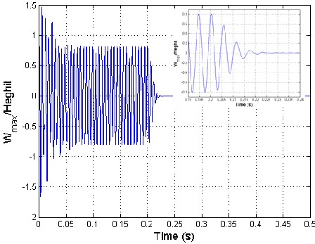
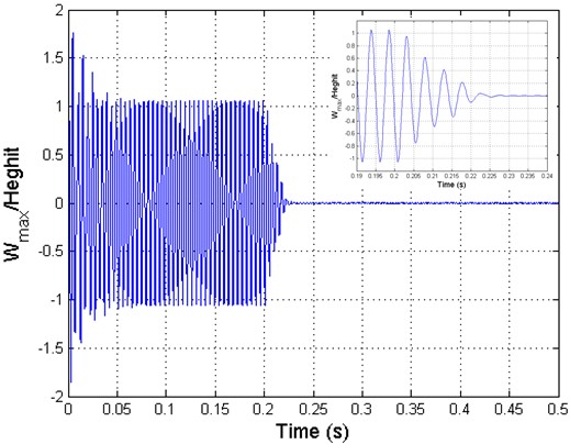
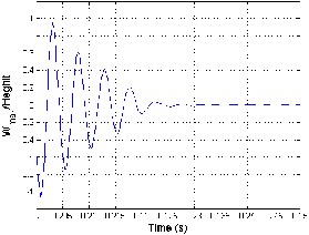
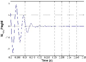
2. four modes were used to model our cases (1,1),(1,2),(1,3) and (1,4). Modal participations were calculated at different va lues of λ or in other words at various values of W max/height. The Runge-Kutta numerical integration method was used to simulate the modal nonlinear models. Limit cycle oscillations (LCO) are associated with panel flutter without thermal load. Free oscillations are generated by the panel when there is no dynamic pressure and there are no other damping and nonlinear effects in the system. The critical dynamic pressure is determined using eigenvalue analysis of the linear system[30]. Purely imaginary eigenvalues are produced in case of free vibration. W hen the aerodynamic pressure applied to the panel introduces damping and flow coupling terms which, lead to oscillations decaying and system has complex eigenvalues with negative real parts. The rat e of oscillations decaying increases as the dynamic pressure increases until it reaches the critical aerodynamic pressure at which there exists a pair of purely imaginary eigenvalues having negative real parts. Beyond this critical aerodynamic pressure, the pair of pur ely imaginary eigenvalues becomes eigenvalues with positive real parts and gives unstable system. The critic al aerodynamic pressure is calculated and found to be 512 using the eigenvalues. Panel flutter limit cycle oscillations at aerodynamic pressure λ= 84 0
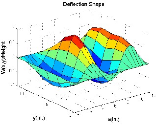
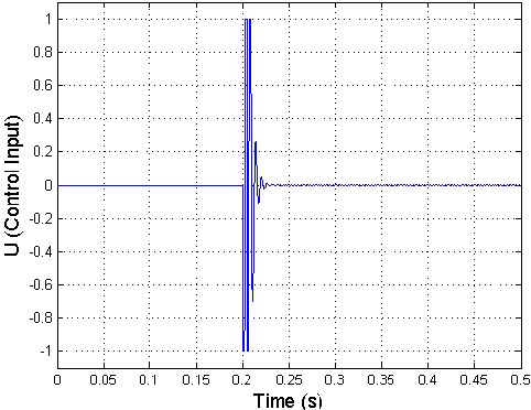
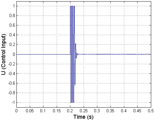
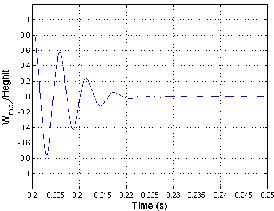
and 1200 are obtained. Linear quadratic regulator (LQR) full state feedback is used to control th e panel flutter oscillations. The controller is activated at time .2 sec as shown in figure 2. The piezoelectric ceramics sense the magnitude of the highly contributing modes of the limit cycle motions of the panel flutter. The sensed flutter (output signals) is fed to the controllers which modify the signals, and is fed back to the actuators, and this actuates the panel to suppress the magnitudes of limit cycles until the s ensor senses no flutter from the panel. The control inputs are the electric fields, generated by the electric potentials applied on the piezoelectric ceramics (actuators). Figure 4.1 shows the mode shapes where, mode shape of a vibrating system is a shape of wave in which all parts of the system move sinusoidally with the same frequency and with a fixed phase relation. Figure4. 2 shows the time history of controlled panel flutter at λ=840 and 1200 respectively. The LCO oscillations are controlled and obtained using the iterative method which, used to determine the optimal location of actuator. The phase plot is defined as plot of all possible values of position and momentum (velocity) variables as a function of time. The phase plot of controlled panel flutter at λ=840 and 1200 is shown in figure 4.3. The control input shown in figure 4.4 is obtained by dividing the original control input by the maximum control
voltage at λ=840 and 1200.
Material | Aluminum (panel) | PZT5A(actuator and sensor) |
Thickness | hs =0.05 in. (0.00127 m) | hp = .015 in. (0.00381m) |
Young modulus | Ep =10 Msi (68.95 Gpa) | Ee =9 Msi (62Gpa) |
Mass density | .2588e-3Ib-sec2/in4 (2700 kg/m3) | .7101×103 Ib-sec2/in4 (7593 kg/m3) |
Poisson’s ratio | Vp=.3 | Ve =.3 |
Charge constant | d31=-7.51×10⁻⁹ in/v (-1.91×10⁻¹⁰ m/v) d32=d31, d36=0 | |
Coercive field | Emax=1.52×10⁴ v/in. (600×103 v/m) |
IJSER © 2013 http://www.ijser.org
International Journal of Scientific & Engineering Research, Volume 4, Issue 12, December-2013 1469
ISSN 2229-5518
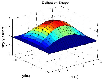
(a) 1st mode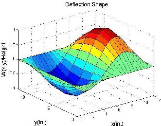
(b) 2nd mode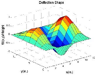
IJSER
(c) 3rd mode
(d) 4th mode
IJSER © 2013 http://www.ijser.org
International Journal of Scientific & Engineering Research, Volume 4, Issue 12, December-2013 1470
ISSN 2229-5518
IJS(a) Maximum DefleEction at λ=840 R
IJSER © 2013 http://www.ijser.org
International Journal of Scientific & Engineering Research, Volume 4, Issue 12, December-2013 1471
ISSN 2229-5518
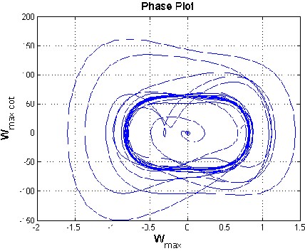
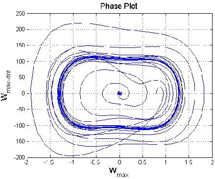
IJS(a) Phase PloEt at λ=840 R
(b) Phase Plot at λ=1200
IJSER © 2013 http://www.ijser.org
International Journal of Scientific & Engineering Research, Volume 4, Issue 12, December-2013 1472
ISSN 2229-5518
IJS(a) The Control IEnput at λ=840 R
(a) The Control Input at λ=1200
IJSER © 2013 http://www.ijser.org
International Journal of Scientific & Engineering Research, Volume 4, Issue 12, December-2013 1473
ISSN 2229-5518
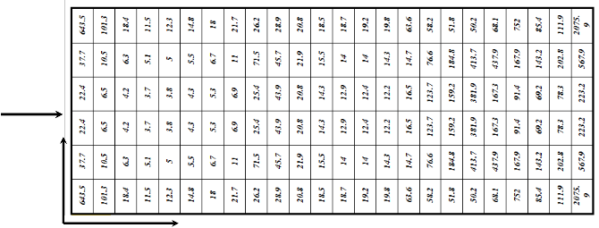
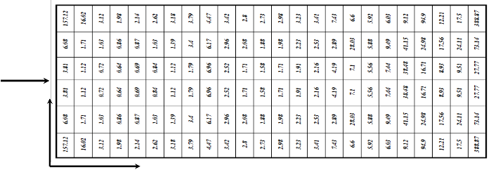
The optimal size and location of piezoelectric material are determined using a combination of the NFCG method and an iterative method. NFCG [2, 7, 27] is used to determine the optimal shape and location of piezoelectric material. Actuator and sensor optimal locations would make the control very effective.![]()
NFCG =√∑ (i=1, 2, 3, …………….. N) (4.1)
Where N is the number of piezoelectric actuator sets, 2n is the number of state variables and is the element of the
feedback gain K from equation (3.7).
W e calculate the NFCG norm for each location. Then the iteration focuses on the area covered by PZT elements determined with NFCG method. In the proposed ad-hock iteration method a random placement of a number of piezoelectric actuator/sensor layers is implemented. For the structural integrity of aircraft panels the damping time of fluttering phenomena should be as small as possible. Thus the smallest time duration between the PZT actuation moment and the complete damping state is the objective function. In this methodology the NFCG is used to select the candidat e position and area for laying piezoelectric actuator sensor for high control authority. Then, the placement iterations will be focused around this candidate area. Thus, the computational ti me will be reduced to less than 1% of the expected computational time of the blind iterative method. Comparin g the damping time recorded when using the NFCG methodology with the proposed methodology in this paper, it is found that the control authority is augmented as the damping time is reduced. On the other hand, the ad-hock iterative method introduced in this work deals explicitly with the targeted damping time, which is not explicitly seen in applying the NFCG methodology. The setting time in the MatLab program is the time at which the maximum displacement per panel height (W max /Height) is less than 0.0005. The NFCG are calculated based on aerodamping coefficient ca =.01 and control-weighting matrix R is 10*I. The comparison between the two methods based on the damping time and the numbers of actuators (size) required for achieving the damping showed that the proposed iterative method gives better performance than The NFCG method as shown in figure 4.5. Figure 4. 5(a) shows that suppression time using the iterative method (0.072 sec) is less than NFCG targeted damping time (0.0836 sec) for the same actuator size and λ=840. Figure
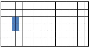
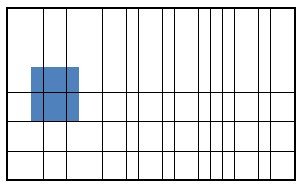
4.5(b) shows that flutter damping needs 0.0581sec damping time with three piezoelectric patches as actuators using the iterative method while, needs 0.2187 sec damping time with four piezoelectric patches at λ=1200. The results shown in figure 5 demonstrate that the iterative method is more efficient than NFCG method. Figure 4.6 and 4.7 indicate that the optimal actuator location located at the panel leading edge (LE or left hand side) which is in agreement with [2, 15 and 26]. The size of piezoelectric is equal to the area of one finite element and the number of piezoceramics patches required for damping are (6 and10) for λ =840 and1200 as shown in figure 4.6 and 4.7. Besides, the configuration in figure 4.6 and 4.7 they illustrate that the optimal shape at λ=840 and 1200 is rectangular shape (one set) using the NFCG method while, the optimal shape is rectangular at λ=840 and multi sets actuator at λ=1200 using the iterative method. It is proved that the resulting optimal location and size at λ= 1200 shown in figure
4.7 works over the entire range 0f λ (from λ=512 to λ=1200). It is found that more piezoelectric material do not provide better performance for flutter suppression where, in some distributions less piezoelectric material gives better performance than more piezoelectric material. Figures 4.6 and 4.7 show cleary that the optimal actuator placement using iterative method is completely different about the optimal placement actuator using lower NFCG norm. Figures 4.6 and 4.7 show also cleary how the optimal locations of actuator change completely for different λ.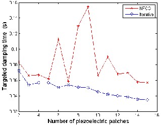
(a) Number of Piezoelectric patches and Time Relation at λ=840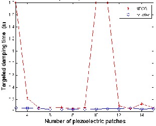
(b)Number of Piezoelectric patches and Time Relation at λ=1200
IJSER © 2013 http://www.ijser.org
International Journal of Scientific & Engineering Research, Volume 4, Issue 12, December-2013 1474
ISSN 2229-5518
(b) Optimal Placement IBased onJIterative MethSod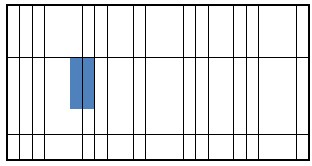
(a) NFCG Norm/100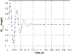
E(c) Optimal PlaRcement Based on NFCG Method
(d) Lateral Deflection 0f Iterative Method (e) Lateral Deflection of NFCG Method
IJSER © 2013 http://www.ijser.org
International Journal of Scientific & Engineering Research, Volume 4, Issue 12, December-2013 1475
ISSN 2229-5518
(b) Optimal placement bIased onJIterative methoSd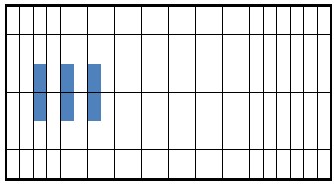
(a) NFCG Norm/1000
E(c) OptimRal placement based on NFCG method
(d) Lateral Deflection of Iterative Method (e) Lateral Deflection of NFCG Method
IJSER © 2013 http://www.ijser.org
International Journal of Scientific & Engineering Research, Volume 4, Issue 12, December-2013 1476
ISSN 2229-5518
A coupled structural-electrical finite element model of isotropic panel with embedded piezoelectric actuators is subjected to supersonic flow induced nonlinear panel flutter. The supersonic piston theory is used to determine the aerodynamic pressure. Simulation of the panel flutter suppression using LQR full state feedback is presented. An ad-hock method and NFCG method are used to determine the optimal location of self-sensing of piezoelectric actuator at different λ. It is proved that the iterative method has better performance than NFCG method where, as the former damps the flutter in short period of time and low numbers of piezoelectric patches. The results demonstrate that iterative method is efficient in piezoelectric actuator placement determination.
[1] Zhou, R.C., Xue, D.Y., and Mei C. Finite element time domain - Modal formulation for nonlinear flutter of composite panels. AIAA Journal, 1994. 32: p. 2044-2052.
[2] Abdel-Motagaly, K., et al. Active Control of Nonlinear Panel Flutter Under Yawed Supersonic Flow. AIAA Journal, 2005. 43: p.
671-680.
[3] Johns, D.J. A survey on panel flutter. Presented at the 21st Meeting of the AGARD Structures and Materials Panel in Nancy. north atlantic treaty Organization advisory group for aerospace research and Development, 1965.
[4] Mei, C., Abdel-Motagaly, K. , and R. Chen. Review of Nonlinear Panel Flutter at Supersonic and Hypersonic Speeds. Applied
Mechanics Reviews, 1999. 52: p. 321-332.
[5] Chowdary, T.V.R., Parthan, S., and Sinha P.K.. Finite element flutter analysis of laminated composite panels. Computers & Structures, 1994. 53: p. 245-251.
[6] Raja, S., et al. Flutter control of a composite plate with piezoelectric multilayered actuators. Aerospace Science and Technology,
IJSER
2006. 10: p. 435-441.
[7] Abdel-Motaglay, K., Chen, R., and Mei, C. Nonlinear Flutter of Composite Panels Under Yawed Supersonic Flow Using Finite
Elements. AIAA Journal, 1999. 37: p. 1025-1032.
[8] Vedeneev, V.V. Panel flutter at low supersonic speeds. Journal of Fluids and Struct ures, 2012. 29: p. 79-96.
[9] Moon, S.H. and Kim , S.J. Suppression of nonlinear composite panel flutter with active/passive hybrid piezoelectric networks using finite element method. Composite Structures, 2003. 59: p. 525-533.
[10] Forster, E.E. and Yang, H.T. Y. Flutter Control of W ing Boxes Using Piezoelectric Actuators. Journal of Aircraft, 1998. 35: p.
949-957.
[11] Lock, m.h. a study of two-dimensional panel flutter. calif ornia institute of techenology,PHD Thesis, 1961.
[12] Pidaparti, R.M.V. Flutter analysis of cantilevered curved composite panels. Composite Structures, 1993. 25: p. 89-93.
[13] Shi, Y., et al. Thermal postbuckling of composite plates Using the finite element modal coordinate method. Journal of Thermal
Stresses, 1999. 22: p. 595-614.
[14] Guo, X. and Mei, C. Application of aeroelastic modes on nonlinear supersonic panel flutter at elevated temperatures. Computers & Structures, 2006. 84: p. 1619-1628.
[15] Moon, S.H. Finite element analysis and design of control system with feedback output using piezoelectric sensor/actuator for panel flutter suppression. Finite Elements in Analysis and Design, 2006. 42: p. 1071-1078.
[16] Moon, S., Yun, C., and Kim, S. Passive suppression of nonlinear panel flutter using piezoelectric materials with resonant circuit. KSME International Journal, 2002. 16: p. 1-12.
[17] Xu ,S.X. , Koko, T.S. Finite element analysis and design of actively controlled piezoelectric smart structures Finite Elements in
Analysis and Design, Research and EmergingTechnologies Department, Canada, 2004. 40: p. 241–262.
[18] Bin Zheng , J.Y. vibration analysis of base structure on SINS using PZT actuators. Eng & Comp Science 2012. 20.
[19] Lotfy, M.E. Active Composite Panel Flutter using Finite Element Method. Aerospace sciences & aviation technology,, 2009. ASAT-13-ST-25.
IJSER © 2013 http://www.ijser.org
International Journal of Scientific & Engineering Research, Volume 4, Issue 12, December-2013 1477
ISSN 2229-5518
[20] Lee, Y.Y., et al. Numerical simulation model of vibration responses of rectangular plates embedded with piezoelectric actuators. Thin-W alled Structures, 2002. 40: p. 1-28.
[21] Otiefy, R.A.H. and Negm ,H.M. W ing box transonic-flutter suppression using piezoelectric self-sensing diagonal-link actuators. International Journal of Solids and Structures, 2011. 48: p. 31-43.
[22] Abdel-Motagaly, K. Finite element analysis and active control for Nonlinear flutter of gompite panels under yawed supersonic flow.PHD Thesis, Aerospace Engineering Old Dominion University, 2001.
[23] Li, J. and Narita ,Y. Analysis and optimal design for supersonic composite laminated plate. Composite Structures, 2013. 101 p.
35-46.
[24] Vedeneev, V.V.Effect of damping on flutter of simply supported and clamped panels at low supersonic speeds. J ournal of Fluids and Structures.
[25] Li, F.M. and Song, Z.-G. Flutter and thermal buckling control for composite laminatedpanels in supersonic flow. Journal of
Sound and Vibration, 2013. 332: p. 5678-5695.
[26] Zhou, R.C., Mei, C.,and Huang, J.-K. Suppression of nonlinear panel flutter at supersonic speeds and elevated temperatures. AIAA Journal, 1996. 34: p. 347-354.
[27] Li, qinqin.active control of large amplitude nolinear free vibrations and nonlinear supersonic panel flutter of beams and composite plates using piezoelectric self-sensing actuator. old dominion university master science thesis, 2005.
[28] Moon, S.H. and Hwang , J.S. Panel flutter suppression with an optimal controller based on the nonlinear model using piezoelectric materials. Composite Structures, 2005. 68: p. 371-379.
[29] Li, F.M. Active aeroelastic flutter suppression of a supersonic plate with piezoelectric material. Internat ional Journal of
Engineering Science, 2012. 51: p. 190-203.
[30] Onawola, O.O. A feedback linearization approach for panel flutter Suppression with piezoelectric actuation. PHD Thesis, Auburn University, Alabama, 2008.
IJSER © 2013 http://www.ijser.org