The main steps followed in this analysis are as described below:
International Journal of Scientific & Engineering Research, Volume 5, Issue 3, March-2014 1056
ISSN 2229-5518
Dr. M. Senthil Kumar
Associate Dean,Prist University.
J.V.Murugalal Jeyan#1,Akhila Rupesh#2
Department Of Aeronautical
Satyam College Of Engineering And Technology,
Tamil Nadu,India
#1ASSISTANT PROFESSOR,
#2 UG SCHOLAR.
Abstract:A single cone probe of the yaw meter is considered and has undertaken analysis using NX NASTRAN. NASTRAN is a finite element analysis [FEA] program that was originally developed for NASA in the late 1960s under United States government funding for the Aerospace industry. The size and geometry of probes shows considerable variation according to their particular use and the number of flow quantities that are required at the same time. Fundamentally, however they all exploit the distribution of pressure which occurs over a body when it is immersed in a moving fluid. These pressure variations depend mainly on wind speed so that with suitable choice of body shape and location of perpendicular holes to serve as pressure tappings,a probe may be used to calibrate in a known wind tunnel; the relationship between pressure and wind speed can then be established over a range of speeds. The design of certain probes involving simple shapes, such as cylinders or
. Keywords:NASTRAN, CalibraItion, CoJne Angle,ReynoSlds number, ConicalEprobes R
spheres, can have some basis in theory, but the final design usually becomes a compromise aimed at minimizing the effect of factors such as
de-attached waves, Mach number and stream turbulence
IJSER © 2014 http://www.ijser.org
International Journal of Scientific & Engineering Research, Volume 5, Issue 3, March-2014 1057
ISSN 2229-5518
Conical probes have been used determination of the Mach number, total pressure and flow direction at supersonic speeds, their shape offering less interference to flow the hemispherical types. Although the inclusion of central pressure tapping precludes a sharp forward apex and the bow wave is detached at all times. The smaller the apex angle of the cone of the wider the range of mach over which a smooth pressure response to obtained. At the sa me time, sensitivity of the side holes to change in the flow direction increases with angle of the cone, so that some compromise is necessary.
Software Specification:
convience the cylindrical face of the probe is fixed. Then various pressures corresponding to various mach are applied individually to the pressure holes. Finally the part is solved and result is obtained. Ratio [NU] is 0.298. Yield Strength is 129566 kPa. Ultimate Tensile Strength is 62001 kPa.
Mass Density of steel is 7.829e-006 kg/mm^3. Young's Modulus [E] is
2.0694e+008 kPa. Poisson's
Solver: | NX NASTRAN |
Analysis Type: | Structural |
Solution Type: | SESTATIC 101 - Single Constraint |
Linearity:Linear |
![]()
The main steps followed in this analysis are as described below:
Name Status Environment Description
Default: NX![]()
![]()
a_catpart_sim1.si m
a_catpart_fem
1.fem![]()
![]()
![]()
![]()
CSYS Groups DOFSets
Regions![]()
Fields
[Filter : Off][Sort : Off]
[Filter : Off][Sort : Off]
[Filter : Off][Sort : Off]
[Filter : Off][Sort : Off]![]()
[Filter :
NASTRAN+ - Structural
Default: NX NASTRAN - Structural
SimulationOff][Sort :
Object Container
Off]![]()
![]()
[Filter :
LoadOff][Sort :
Container
Off]![]()
[Filter :![]()
ConstraintOff][Sort :
Container
Off]
NX NASTRAN -SESTATIC 101 -![]()
Solution 1 Active
Structural
Single Constraint
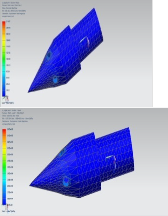
The material used is Steel belonging to material category “METAL” and material type “ISOTROPIC”.Intially the part is opened and meshed. The probe is meshed into 3016 elements and hence about
5760 nodes are present. After meshing the part is given constraints. For
IJSER © 2014 http://www.ijser.org
International Journal of Scientific & Engineering Research, Volume 5, Issue 3, March-2014 1058
ISSN 2229-5518
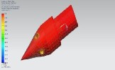
Mach Displacement [max][mm]
0.2
X Y Z
1.6
Mach Displacement [min][mm]
0.2
1.6
X Y Z
IJSER
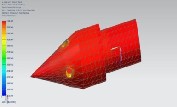
Mach Stress [max][KPa]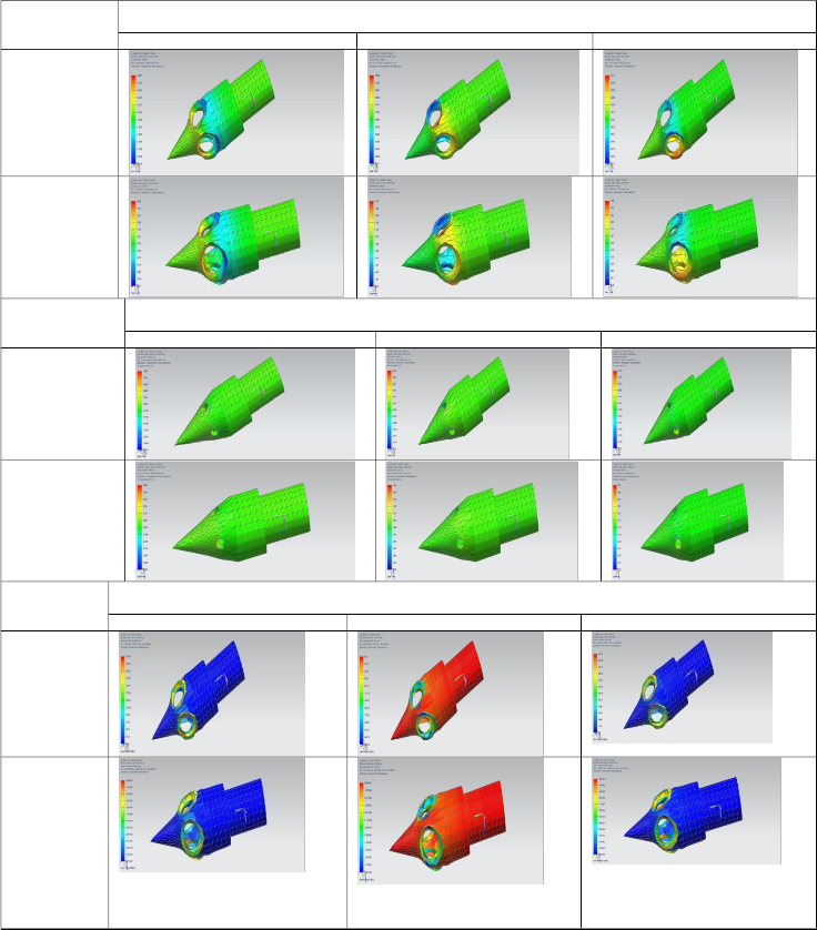
0.2
min principal max principal Shear
1.6
IJSER © 2014 http://www.ijser.org
International Journal of Scientific & Engineering Research, Volume 5, Issue 3, March-2014 1059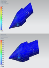
ISSN 2229-5518
Mach | Stress [min][KPa] | ||
Mach | min principal | max principal | Shear |
0.2 |
| ||
1.6 |
|
TABLE II
IJSER
IJSER © 2014 http://www.ijser.org
International Journal of Scientific & Engineering Research, Volume 5, Issue 3, March-2014 1060
ISSN 2229-5518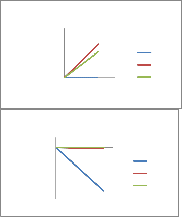
IV.GRAPHICAL RESULT
1.5E+09
1E+09
500000000
0
0 500000 1000000
min prin max pri shear
200000000
0
IJSER
-2E+08
-4E+08
-6E+08
-8E+08
-1E+09
0 400000 800000
min pri max prin shear
IJSER © 2014 http://www.ijser.org
International Journal of Scientific & Engineering Research, Volume 5, Issue 3, March-2014 1061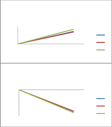
ISSN 2229-5518
3
2 X
1
0 Y
0 200000 400000 600000 800000 Z
0
0 200000 400000 600000 800000
-1 X
-2 Y
-3 Z
IJSER
IJSER © 2014 http://www.ijser.org
International Journal of Scientific & Engineering Research, Volume 5, Issue 3, March-2014 1062
ISSN 2229-5518
The present design and fabrication of the conical probe setup was done successfully and the results predicted state that 1.1mm dia hole can be used up to a mach number range of 2.5. in one single probe 4 holes can be tapped for flow characteristic measures inside a tunnel test section up to a minimum of 0.1m test section to maximum of 0.6m test section The material[steel] which are used to fabricate conical probe is made by high strength high hardness metals which are heat treated. The final model is part analyzed using NASTRAN.
Apart from the efforts from both of us, the success of this project depends largely on the encouragement and guidelines of many others.Wewould like to show our greatest appreciation to Dr.M.Chentil Kumar. Without his encouragement and guidance this project would not have materialized.We take this opportunity to express my gratitude to the people who have been instrumental in the successful completion of this project.
[1] A.L. Braslow and E.C. Knox, Simplified Method of Determination of Critical Height of Distributed Roughness Particles for Boundary –Layer Transition at Mach Numbers from 0 to 5, NASA TN 4363, September 1958.
[2]Kopal, Z. Tables of supersonic flow around cones. Mass. Inst. Technology Tech. Report No. 1, 1947.
[3] HESS, J.L., SMITH, A. M. O., RIVELL, T. L. Systematic design of improved static pressure sensing probes. Douglas Aircraft Co. Inc., Engineering paper No. 1181, October, 1961.
[4] SWALLEY, F. E. Measurement of RIVELL, T. L. Systematic design of improved static pressure sensing probes. Douglas Aircraft Co. Inc., Engineering paper No. 1181, October, 1961.
[4] SWALLEY, F. E. Measurement of flow angularity at supersonic and hypersonic speeds with the use of a conical probe. NASA TN D-
959, 1961.
[5] ANDREWS, D. R., SAWYER, W. G.
[6] RANEY, D. J. Flow direction measurements in supersonic wind
tunnels Current papers aero. Res. Coun. Lond, No. C. P. 262, 1956.
[7] BARRY, F. W. comparison of flow directions probes at supersonic speeds.J. aeronaut.Sci., 1962 [9], 750.
IJSER © 2014 http://www.ijser.org
International Journal of Scientific & Engineering Research, Volume 5, Issue 3, March-2014
ISSN 2229-5518
1063
I£ER 2014