electrical load without man-made conductors. Wireless transmission is useful in cases where interconnecting wires are inconvenient, hazardous, or impossible.
International Journal of Scientific & Engineering Research, Volume 4, Issue 12, December-2013 188
ISSN 2229-5518
Advanced Trends in Wireless Electricity
Transmission using Semiconductor Devices
Sumit Sharma
Dept. of Electronics & communication Engineering
Apex Institute of Engineering and Technology, Jaipur India
Abstract--- in this paper, we describe the advance trends in the system of transmission of electric power without using the actual wires but with the help of conversion of electricity into waves and then transmitting it into the atmosphere with the speed of light i.e. 3 x 10⁸ m/sec.The conversion efficiencies are more than 75% at the transmission distance of 300mm at lab. It is used to transmit electricity at a large distance of high frequency using electromagnetic waves such as microwaves. Such technology is used to transmit electric power from one place to other replacing the old interconnecting mediums called wires. The technology could be more developed by the use electronics that would be described in the paper. The low power could be transmitted using
the special microwave or laser devices later on received by distant receivers containing rectenna providing an efficiency of more than 80% and convert back all microwave into electric power. The electronic devices and transducers could be useful in amplifying the power received and later on providing the correct frequency of transmission of 50 Hz in India and sent for domestic purposes. This system takes us to an era of low losses of the electric power by heat or by turbulence and donates an amount of good efficiency. W e see the significant improvement in the efficiency and reliability of wireless transmission network. The same experiment is carried out using the present concepts at a ground level up to a few centimetres will be described in paper. The review will also discuss on advantages and short comings of the third generation power transmission system.
IJ————S—————— E———————R———
IJSER © 2013 http://www.ijser.org
International Journal of Scientific & Engineering Research, Volume 4, Issue 12, December-2013 189
ISSN 2229-5518
WIRELESS power transmission has been a topic of continued interests since the last several decades, with an emphasis made initially on long-distance high-power microwave transmission from one place to other place. Firstly we have achieved it in ground level using latest techniques and simple transmission and receiving circuit and using different methodology of induction and microwave transmission. Once it is developed at the ground level it would be easy for the mankind to develop it in the large field also and also in the favour of the mankind.
Wireless power or wireless energy transmission is the
It includes the system by which the transmission of power takes place in our life and defines the concept of the transmission, channel and receiving module.
The power can be transmitted from one place to other place by three ways called the
In this process whenever a current with a voltage is passed through a inductor coil, it stores the energy and produce electric flux which leads the production of electromagnetic field. These fields carry electric voltage and current with them. When these electric fields link with the other coil produces the voltage in the other coil also. Such thing is called the concept of induction.
Even this process is not suitable for the health and
IJSER
transmission of electrical energy from a power source to an
electrical load without man-made conductors. Wireless transmission is useful in cases where interconnecting wires are inconvenient, hazardous, or impossible.
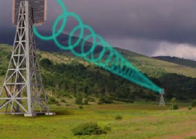
Figure I: Ground level transmission
In today’s world everything is based on the wireless systems. Communication systems radio and TV signals Walkie talkie system etc. and the wireless system of power transmission is based on same communication system but entirely different from it that we will see further.
Figure II: Solar based transmission
environment as the electromagnetic field causes a type of clotting and cancer among the humans and also causes major health hazardous.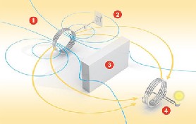
Figure III: Electromagnetic induction
Microwave are much developed then the electrostatic and electromagnetic induction. Power transmission via radio waves can be made more directional, allowing longer distance power beaming, with shorter wavelengths of electromagnetic radiation, typically in the microwave range. A rectenna may be used to convert the microwave energy
IJSER © 2013 http://www.ijser.org
International Journal of Scientific & Engineering Research, Volume 4, Issue 12, December-2013 190
ISSN 2229-5518
back into electricity.
Figure IV: Microwave transmission
So microwaves are proved to be much safe and reliable to transmit electric power over a distance of more than a kilometre.
LASER (Light Amplification by Stimulated Emission of
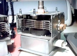
Figure V: Magnetron
The devices which are used to produce the microwaves by using some electric source or oscillator are called microwave generators. These are high efficiency generators which produces microwave at a constant frequency. The microwave transmitting devices are classified as Microwave Vacuum Tubes (magnetron, klystron, Travelling Wave Tube (TWT), and Microwave Power Module (MPM)). The other choices of frequencies are 8.5 GHz, 10 GHz and 35 GHz. The highest efficiency over 90% is achieved at 2.45 GHz among all the frequencies.
antenna can also be used for the receiving side also which is
IJSER
Radiation) is another method of transferring of electric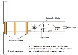
power by amplification and stimulation method. Power can be transmitted by converting electricity into a laser beam that is then pointed at a solar cell receiver. This mechanism is generally known as "power beaming" because the power is beamed at a receiver that can convert it to usable electrical energy.
also used to receive signals at the receiver module to receive
and work out on the signal received.
4.3 Rectenna:
4. Components of wireless transmission: Components refer to the different stages and equipment which are used to carry out a particular technology. The Primary components of Wireless Power Transmission are Microwave Generator, Transmitting antenna and Receiving
antenna (Rectenna). The components are described below:
Figure VI: Rectenna circuit
RECTENNA as the name suggests denotes the rectifying antenna which is used to convert the microwave back to electricity. The rectenna is a passive element consists of antenna, rectifying circuit with a low pass filter between the antennas and rectifying diode. Scotty barrier diodes (GA As-W, Si, and GA As) are usually used in the rectifying circuit due to the faster reverse recovery time and much lower forward voltage drop and good RF characteristics. The diameter of rectenna would be in miles. Deploying in the earth surface in a diameter would allow it to receive
IJSER © 2013 http://www.ijser.org
International Journal of Scientific & Engineering Research, Volume 4, Issue 12, December-2013 191
ISSN 2229-5518
more and more microwave and thus converting it to electric power.
5. GROUND LEVEL TRANSMISSION
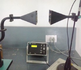
The transmission of electricity at the ground level is achieved using the different instruments developed and processed. It is carried by using a transmission module and a receiver module. It also displays the transmission of AC supply using microwaves at a shorter distance of 15 to 20 cm. The voltage of the transmitting wave and frequency is maintained and then sent. Some waves are received at the receivers end and then falls on the rectenna. The rectenna converts the microwaves to the electricity and thus we can use it for domestic power. The output we can also see on the oscilloscope also which displays the respective waveforms of the receivers end. The complete setup of the receiver and the transmitting module is presented below.
this device is just to convert the coming electric power to the microwaves whose frequency and voltages are predefined by the step down transformer.
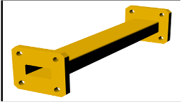
Figure VII: Waveguide
A waveguide is a structure that guides waves, such as electromagnetic waves or sound waves. The original and most common meaning is a hollow conductive metal pipe used to carry high frequency radio waves, particularly microwaves. Waveguides are the devices which works as a
microwave travel line for the travel of the microwave in
IJSEwhich the atteRnuation of the microwave is done to make it
The transmitting circuit consists of:
The cavity magnetron is a high-powered vacuum tube that generates microwaves using the interaction of a stream of electrons with a magnetic field. The devices used to convert electricity to the microwaves. This device will convert the coming A C power coming from step down transformer to the microwaves for transmitting through the waveguide or helical antenna which are two basic methods for the
transmission of the microwave produced. The main work of
ready for the transmission through the transmission props.
The receiving module is the module which consists of the receiving circuit which is used to receive the transmitted microwave from transmitting module. It consists of the following components:
IJSER © 2013 http://www.ijser.org
International Journal of Scientific & Engineering Research, Volume 4, Issue 12, December-2013 192
ISSN 2229-5518
the microwave coming from the transmitting module and thus convert the microwaves back to electric power.
6. OUTPUT:
by using carbon grapheme technology. By using such technology the size of the components can be reduced to large extent and their efficiency can be increased. Such technology is proved to be a boon for nature and mankind.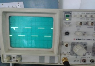
.
1. Energy delivered anywhere in the world
2. Zero fuel cost
3. Less losses
4. Less use of copper wires
5. More efficiency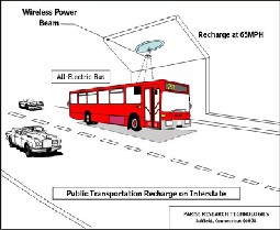
6. Minimum long-range environmental impact
Figure VIII: Transmitting microwave
The microwave received at the receive end can be seen at
the cathode ray oscilloscope determining its different properties like voltage current frequency which can be calculated easily by it. The microwave received has some amount of voltage and current which we need to be received. Such calculations can be performed by the oscilloscope for determining the different parameters.
The above procedure of transmission of electricity can be carried out by using a special evolved technique called the technique of the carbon nano tubes or the grapheme technology in which the special semiconductor materials
like solar cells diodes and other materials are manufactured
Figure IX: charging by Witricity
1. Possible health hazards
2. Huge capita investment in the deployment system.
3. Unbearable change of the existing transmission system.
IJSER © 2013 http://www.ijser.org
International Journal of Scientific & Engineering Research, Volume 4, Issue 12, December-2013 193
ISSN 2229-5518
The applications of the long-distance high-power wireless transmissions are primarily applied to the space solar power satellites and the far-distance remote site power supplies, the short-range low-power wireless transmissions are applied to the power grid system to form a wireless power supply, the wireless charging system and also the medical sensor network and imaging systems. The carbon nanotubes will be proved as a boon for the research and industries. Presently it is being used in the solar cell application to improve the efficiency and reduce the weight and cost. by this method we can refine the method of solar power and Witricity transmission and hence can achieve
greater efficiency.
[1] AristeidisKaralis, J .Giannopoulos’ Efficient wireless non-radiative mid- rangeenergytransfer Analysis of Physics Vol. 323, Issue 1, pp.34- 43 April 27,( 2007).
[2] "Experimental Thin-Film, Etched-Circuit Rectenna",
W.C. Brown, J.F. Triner, (1982) International Microwave Symposium Digest, IEEE Cat. No.82CH1705-S
[3] Kurs, A. Karakis, R. Moffatt, J. D. Joannopoulos, P.
Fisher, and M. Soljacic“Wireless power transmission via strongly coupled magnetic resonances,” Science, vol.
317, pp. 83–86, Jul.(2007)
[4] http://en.wikipedia.org/wiki/Wireless_power
[5] http://electronics.howstuffworks.com/everyday-![]()
IJSER © 2013 http://www.ijser.org
International Journal of Scientific & Engineering Research, Volume 4, Issue 12, December-2013
ISSN 2229-5518
194
IJSER <b) 2013