International Journal of Scientific & Engineering Research, Volume 2, Issue 12, December-2011 1
ISSN 2229-5518
Admission Control and Performance Evaluation for Distributed Door Entry Wireless Networks
Wael Hosny Fouad Aly, Haytham Aboulabbas, Moustafa H. Aly, Hossam Eldin Moustafa
Abstract: In this paper, we propose a novel smart access control system for large enterprises. The proposed system performs the following functions: (1) limits access to secured areas in a given physical facility only to authorized users, (2)provides authorized users with configurable and differentiated access rights to the same premises based on their assigned credibility and time-schedules, (3) maintains centralized event logs with date/time stamp for all users that have granted access to the system, and (4) keeps track of all their movement activities across the premises, allowing for further analysis of their behaviour during working hours. All of these functions are mainly intended to: (1) be carried out automatically and wirelessly with neither human intervention nor slowing down the organization’s workflow, (2) avoid installation cost overhead,(3) minimize the running cost, (4) simplify system repairs and shorten it downtime, and (5) allow for future upgrades with almost little or no hardware changes along with slight firmware code modifications. The proposed system is implemented as a prototype model that presents both the hardware and the firmware aspects of the design. The built prototype shows success of the proposed system and hence it is promising for physical implementation in real systems at larger scales.
Keywords: Wireless Networks, Embedded system, access control, authentication, radio frequency identification (RFID), ZigBee, XMOS.
1. Introduction
—————————— ——————————
and the embedded electronic information for each tag can be over-written repeatedly. The increased reading distance
Committee of National Security Systems (CNSS) [1] defines the term access control as the process of granting or denying specific requests: 1) to obtain and use information and related information processing services; and 2) to enter specific physical facilities(e.g., Federal buildings, military establishments, and border crossing entrances). Physical access control is the focus of this paper. It may come as a surprise that modern computerized physical access control systems are the fastest growing sector within the entire security industry, with installations in almost all new buildings and upgrades to existing systems at all levels [2]. In today’s environment, it’s more important than ever to deploy a building access control system with state-of-the-art security features. The proposed system possesses the following features, which are expected not only to combat theft and vandalism but also to improve company productivity and increase payroll accuracy:
- RFID technology: The proposed system employs RFID tags as electronic keys for accessing the system. Electronic keys imply the implementation of authenticated users’ database. If a tag is lost, it can be immediately removed from the database and a new one can be issued. If an employee leaves the company, his or her access rights can be deleted within seconds. This greatly lowers the overall exposure to risk. With respect to users, using single unique RFID tag grants him access to all his assigned premises within the enterprise, so there’s no chance of forgetting the key for a particular premise. RFID tags can be read from much further distances than other traditional technologies
————————————————
Wael Hosny Fouad Aly, Haytham Aboulabbas M., Moustafa H. Aly, College of Engineering and Technology, Arab Academy for Science, Technology & Maritime Transport, Alexandria, Egypt drwaelaly@gmail.com, haythamaboulabbas@hotmail.com, drmosaly@gmail.com. Hossam Eldin Moustafa: Faculty of Engineering, University of Alexandria, Alexandria,
allows for automated operation of the system without slowing down the organization’s workflow and it is crucial for user tracking capability. Information about employee access, attendance, and entered premises, can then be automatically, easily, and efficiently monitored and stored in a centralized database for further analysis.
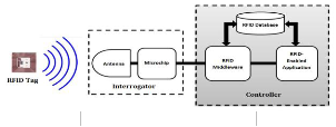
Fig 1:The basic building blocks of an RFID system
- Centralized management: the proposed system is manageable from a central terminal (or node). This allows for accessing the distributed autonomous remote (or door- entry) nodes from a single monitoring platform. This increases the overall system effectiveness and reduces staffing requirements.
- Wireless nodes communication: in the proposed system, the central node (or terminal) wirelessly communicates with the distributed autonomous remote (or door-entry) nodes. This in turn largely reduces the installation cost overhead of the system by avoiding the hassle or wired infrastructure required for connected the nodes with the central terminal. Moreover, it helps the scalability of the system.
- User-level permissions: the proposed system allows the administrator to freely assign configurable adaptive- credibility and time-schedules to the users. This allows for
Egypt ahossam@cs.ucf.edu
IJSER © 2011
http://www.ijser.org
International Journal of Scientific & Engineering Research, Volume 2, Issue 12, December-2011 2
ISSN 2229-5518
differentiated access rights to the same premises within the
enterprise for different users. It minimizes the exposure to risk by granting users no more site access than is necessary.
- Detailed logging: the proposed system maintains a centralized time-stamped access log for every entry to the enterprise, allowing for exactly knowing who accessed the enterprise, and when they did so. This in turn provides the company with integral automated time and attendance management solution, which saves the employee’s labour time, reduces payroll errors, and eliminates the costs related to obsolete and paper-based time and attendance management systems.
- User tracking: the proposed system keeps track of all users’ movement activities across the premises of the enterprise. This provides the system administrator with all the information necessary for potential further analysis of the employees’ behaviour during working hours. It would then allow for providing potential efficient salary pay system for companies depending on the effective time spent in work-relating premises and excluding the time spent in the other non-work-relating premises according to specific scheme as introduced by [3]. The tracking information maybe later visualized on the screen, allowing for proactively locating the employees within the enterprise.
- Future upgrades: the proposed system employs an event- driven multi-threaded processor from XMOS as the main controller for the nodes. The employed processor’s architecture allows for building the system with a modular philosophy. This not only means that the system can be tailored to the needs of individual customers, but it also represents an important factor for further development of the system. Each individual module of the proposed system can then be further refined independently of the other modules. As a result, improvements can be introduced continuously as soon as they have been thoroughly tested with almost little or no hardware changes along with minimum software modifications, always giving customers access to the latest execution.
2. RFID Technology
The emerging technology of RFID promises to be a comprehensive approach to a wide range of applications. RFID technology stores and remotely retrieves data using devices called RFID tags. A tag is a device that can be applied to a product, animal, or person for the purpose of identification and tracking using radio waves [4][5].The history of RFID is integrated with the history of other automatic data capture devices, such as bar codes [6][7]. An RFID system basically consists of three components [8]:
- A tag (sometimes called a transponder): which is composed
of a semiconductor chip, an antenna, and sometimes a battery.
- An interrogator (sometimes called a reader): which is composed of an antenna, an RF electronics module, and a control electronics module.
- A controller (sometimes called a host): which most often takes the form of a PC, workstation, or embedded system running database and control (often called middleware) software.
Fig. 1 shows the general layout of an RFID system. The RFID reader sends out electromagnetic (EM) energy that forms a magnetic field. The microchip that reside on the tag, which contains data for the object to which is it attached, modulates the EM waves and generates a new series of EM waves containing information that is read by the RFID reader [9][10]. RFID tags can be either active or passive devices. While both use RF energy to communicate between a tag and a reader, the methods for powering the tags are different. Active RFID devices are self-powered and contain a battery within the tag. On the other hand, passive RFID tags are inductively powered by the reader, and this power allows it to transmit its information back [11][12][13]. Currently, many commercial applications for RFID systems exist; RFID is already driving shifts in supply chain and retail capabilities. Other applications include car tracking, airport security checks (passports and baggage), tracking pets, timing for sports, product tracking through manufacturing and assembly, toll payment, and libraries [14][15][16][17]. Nevertheless, one of the promising potential applications of RFID technology includes the improvement of access control systems. RFID offers a more automated and informative technology that could be used to identify persons. Employing RFID in access control systems will not only increase convenience and improve the enterprise productivity, but it would also allow for tracking of who has entered the premises at a given time. Hence it increases the building security and thus the safety of the occupants.
However, as extensive as the possibilities of RFID technology, its use is still limited by the anticipated difficulties of implementation. For a typical application, such as deployment in the proposed system, multiple RFID readers are densely distributed throughout the premises with a single central node (or terminal) to control the network and manage the vast amount of data collected from the remote (or door-entry) nodes. Because of the number of readers transmitting their data to the central node through hardwired connections, installing a complete wired infrastructure is necessary to accommodate the data transmission. This increases the installation cost overhead and the hassle of implementation, detracting from the
IJSER © 2011 http://www.ijser.org
International Journal of Scientific & Engineering Research, Volume 2, Issue 12, December-2011 3
ISSN 2229-5518
appeal of RFID. To improve this situation, the major
ambition of the proposed system is to enable a wireless communication between the central node and the distributed door-entry nodes, which are spread throughout the premises. Having door-entry nodes which are wirelessly networked to the central node would lower the installation cost overhead, simplify system administration and repairs, minimize its downtime, and provide for the scalability of the system.
3. ZigBee Technology
Enabling wireless communication between the central terminal and the door-entry nodes has some critical design issues. The first critical design decision in the implementation of the proposed system is the selection of the wireless protocol to use. The benefits of using a standard wireless communication protocol rather than other available proprietary wireless protocols are obvious. A standardized protocol functions universally. After deciding that a standard was the best choice, the available wireless standards were evaluated based on selected criteria. For a viable employment by the proposed system, low power consumption, long range, support for a large network size, and low cost were imperative requirements.
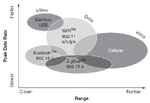
One of the available wireless standards is the ZigBee standard (a comparison is shown in Fig 2). While most wireless standards are striving to go faster, ZigBee aims for low data rates. While other wireless protocols add more and more features, ZigBee aims for a tiny stack that fits on 8-bit microcontrollers. While other wireless technologies look to provide the last mile to the Internet or deliver streaming high-definition media, ZigBee looks to control a light or send temperature data to a thermostat. While other wireless technologies are designed to run for hours or perhaps days on batteries, ZigBee is designed to run for years. And while other wireless technologies provide 12 to 24 months of shelf life for a product, ZigBee products can typically provide decades or more of use [18].
Fig 2: Wireless technologies compared [18]
ZigBee is outlined in IEEE standard 802.15.4, which defines the Physical (PHY) and Medium Access Control (MAC)
layers while the ZigBee protocol working on top of it would
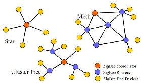
perform the Network layer (NWK) and Application layer (APL) tasks[19][20]. The PHY, MAC and NWK layers would handle how the underlying wireless data transmission would be carried out and how the network of RF transceivers would be organized while the APL layer would handle the tasks associated with each autonomous device. The ZigBee standard employs a suite of technologies to enable scalable, self-organizing, self-healing networks that can manage various data traffic patterns [21].The ZigBee Alliance is an industry association that supports the use of the technology, enabling it for Wireless Sensor Networks (WSNs) [22].The ZigBee standard supports multiple topologies, namely, star, peer-to-peer, and mesh configurations [19][23][24].
Fig 3: ZigBee network topologies [21]
ZigBee-compliant products operate in two main modes: non-beacon and beacon. In beacon mode, the ZigBee coordinator will periodically generate a super frame that is identified as a Beacon frame. Since the emission of the super frame implies the use of time slots, every end device must synchronize with the super frame in the time domain. Each end device participating in the Beacon method is assigned a specific time slot that it can use to transmit and receive data. Normally, the ZigBee end device in a Beacon-enabled network will synchronize with the ZigBee Coordinator's Beacons and wake up just before the Beacon is to be generated, hopefully do its data transmission and reception inside the Beacon's active time period, and go back to sleep awaiting the next Beacon period. In contrast, the non-beacon mode is simpler and uses peer-to-peer networks. In this type of network, the ZigBee coordinator, and probably the ZigBee routers, will have their radios continuously active, requiring a more robust power supply. However, non- Beacon-enabled network allows for heterogeneous network in which some devices (the ZigBee coordinator and probably the participating ZigBee routers) receive continuously, while others (the ZigBee end devices) only transmit when an external stimulus is detected [25].
The ZigBee technology displays three different device types that operate in a self-organizing application network: ZigBee Coordinators (ZC) and ZigBee Routers (ZR), which are Full Function Devices (FFDs); and ZigBee End Devices (ZED), which are Reduced Function Devices (RFDs). These physical devices are used to create a ZigBee network
IJSER © 2011 http://www.ijser.org
International Journal of Scientific & Engineering Research, Volume 2, Issue 12, December-2011 4
ISSN 2229-5518
[26][27]. The ZC acts as the network head and is typically mains powered, and there can only be one PAN coordinator in a network. The ZR, which is an FFD, can perform the function of routing the data between the nodes. ZEDs are the leaf nodes. They check the availability of the nodes to send data, have minimum functionality, and are always battery-powered [21][21]. Fig. 3 shows the mesh, cluster tree, and star network configuration.
4. RFID versus ZigBee
RFID and ZigBee are two wireless technologies each of
which has its own developed hosts of applications independent of the other. Each has benefits, while ZigBee supports advanced sensor networks; RFID is suitable for low-power wireless authentication and tracking of people. Therefore, ZigBee is not recognized as an alternative for RFID, but a network platform that enables RFID devices to communicate with each other. The ambition of the proposed system is to combine the two technologies together to create a novel of extended features capabilities for the next-generation physical access control systems. Combining the two technologies, the proposed system shows success and provides high level of scalability to be physically implemented in real systems at large scales. Besides, the ZigBee network enables the proposed system to enhance the essential manufacturing factors such as potential battery-powered hand-held access points (or door- entries), robustness, extension of ranges for potential scalability, and avoidance of the hassle encountered for practical installation of such system, including installation cost and hardwire infrastructure necessary for connecting the nodes.
5. Software-Defined-Silicon (SDS)
The next critical design decision in the implementation of the proposed system is the selection of the programmable chip that would reside in the nodes to manage their operations and could efficiently manipulate the potential vast amount of data transferred back and forth in real-time basis. For the proposed system to be practically feasible the system might be challenged by potential requests for customized and differentiated access requirements and security levels in short time frames.The product that misses its market window is a total waste of development effort.In this environment two factors become crucial: flexibility and simplicity. For many years Application Specific Integrated Circuits (ASICs) or Field Programmable Gate Arrays (FPGAs) allowed system designers to meet very specific product design requirements. However, the design process involved is complex, time-consuming and expensive. Technologies such as microcontrollers or Digital Signal
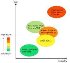
Fig 4:XS1-L compared to popular FPGA families [31]
Processors (DSPs) provide simplicity, but they lack the flexibility needed to meet rapidly changing market requirements [28][29][30][31].
The newly emerging programmable chips of XMOS [32] are selected to be the main controllers of the nodes. XMOS delivers a technology that provides the flexibility of FPGAs or ASICs with the design simplicity of processor-based designs. The XCore [33], 32-bit user-defined embedded processor developed by XMOS, significantly lowers development time and system bill of materials cost. It combines the code efficiency of a RISC processor, the computational performance of a DSP, and the unique flexibility of implementing all peripherals through user- defined “C” software. Fig. 4 shows the XS1-L family (single XCore) with respect to the price, capability (capacity and performance) and power consumption compared to various FPGA device families. A single core XS1-L device offers a capacity for general digital logic implementation roughly comparable to an FPGA having 7-20K logic elements (roughly 70K-200K ASIC gates) [31].
XOMS delivers a new class of programmable semiconductor which it calls Software-Defined-Silicon (SDS) [34]. SDS provides not only software programmability, but also hardware re-configurability through an event driven, multi- threaded processor array on a single chip which possesses high level of performance and flexibility. The XCore processor runs multiple real-time tasks simultaneously using hardware threads and it is yet capable of performing low level and real-time tasks, allowing for the implementation of entirely software-driven hardware interfaces.
Table 2: Interface Examples
IJSER © 2011 http://www.ijser.org
International Journal of Scientific & Engineering Research, Volume 2, Issue 12, December-2011 5
ISSN 2229-5518
| XS1-L | FPGA | ASIC |
F u n c t i o n | Threads | MIPS | Memory | GPIO | Logic Cells | Nand2 Gates |
USB2+2EP | 5 | 400 | 30794 | 12 | 4400 | 44000 |
Ethernet MAC | 5 | 250 | 9982 | 14 | 3600 | 36000 |
TCP/IP | 1 | 50 | 400000 | 0 | 6100 | 61000 |
S/PDIF | 2 | 100 | 5036 | 2 | 800 | 8000 |
I2C Master | 0.5 | 50 | 3044 | 2 | 700 | 7000 |
SDRAM Interface | 1 | 100 | 2974 | 30 | 1100 | 11000 |
Thanks to SDS technology, the proposed system is built with a modular philosophy. The node architecture composes of independent hardware modules which are all interfaced to the XMOS chip that resides in the node. The XMOS chip then takes the role of the co-operation management of the modules. This means that it is extremely simple to add, remove, or update hardware modules of the node to fit differentiated customer needs with each module of additional functionality is implemented as an independent module with almost little or no hardware changes along with slight firmware code modifications. This not only simplifies repairs and servicing of the system and shortens its downtime, but it would also give us exceptionally wide choices that enable the system to be customized to fit special demands as well as potential future upgrades. Upgrading and evolving a product often requires the addition of new silicon devices on the PCB which brings with it significant verification work. However, being able to modify the features of the system without changing the physical hardware design is valuable in saving time and money. The benefits of developing multiple products from a single hardware platform using a firmware change to add, remove or modify features are well known, however this has previously been too expensive for high volume products. SDS differs from existing technologies by taking an entirely software approach to provide configurability and programmability. It uses small arrays of processors instead of large arrays of gates with the benefit that the silicon area and hence cost is dramatically reduced [35]. Table 1 list a range of interface examples and compares the utilization of XCore resources and FPGA logic elements required to implement the protocol [31].
The proposed system utilizes UART, I2C, and SPI software-
driven serial protocols to interface to the hardware modules that reside on the node.
6. System Model
In this section, the proposed system operation is summarized. System-level requirements and considerations are analyzed. The proof-of-concept autonomous nodes are developed.
6.1 System Analysis
The proposed system consists of a central node (or terminal) and a set of autonomous door-entry nodes (or access points) which are wirelessly networked to the central node via the IEEE 802.15.4 wireless communication link. The central node provides centralized system configuration and monitoring, as well as authorized users’ database administration. It is also obligated to maintain centralized time-stamped event logs of all authorized users that have granted access by the system along with detailed footprints of all their movement activities across the premises of the enterprise, allowing for potential further analysis of their behavior during working hours. The door-entry nodes are spread at the main entrance gates of the enterprise, secured offices’ doors, and wherever user tracking is required to be maintained by the system. Fig. 5 depicts the proposed system model. For an enterprise employing the proposed system, a user, according to his pre- assigned credibility and time-schedule, may be authorized to access certain areas during certain times, and otherwise prohibited to do so. For instance, an employee may be granted access to his office all day, but only allowed access to some work-relating premises during working hours, and never allowed access to other premises. The system will be obligated to automatically maintain each employee with his assigned access level. If the employee were to quit his job, he could either be forced to hand in his RFID card, or more desirable in case the card was forgotten or lost, have his RFID card disabled.
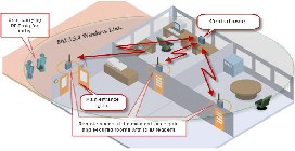
Fig 5: System Model
In general, the system is considered to be an online system if the door-entry nodes are able to go online and query a centralized database from the central terminal whether a person is granted access or not. Conversely, it is considered an offline system if the door-entry nodes already have all the data necessary for making the decision without going online. Consequently, reliability concerns differ for an online system, where communication between the door-entry nodes and the central node becomes sensitive to system operation,
IJSER © 2011 http://www.ijser.org
International Journal of Scientific & Engineering Research, Volume 2, Issue 12, December-2011 6
ISSN 2229-5518
compared to in an offline system where accommodation
and protection of the local storage of information within
the door- entry nodes become critical instead.
In the proposed system, different combinations of online
can be created, allowing for meeting the ever
differentiating customer demands.
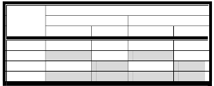
Table 2: Time schedules
Time Interval
and offline operations are implemented. The proposed
system is developed to have offline capabilities for user
Time
Schedule
From To
Date Time Date Time
authentication session but be wirelessly maintained for
centralized system configuration and monitoring, users’ database administration, and access logging. Offline capabilities have the advantage of not depending upon a functioning network which in turn delivers higher reliability and lower access times, allowing for continuous and smooth system operation with neither overwhelming the wireless network nor slowing down the organization’s workflow. Nevertheless, because of the wireless functionality possessed by the system, full online operation may then be easily implemented at a later stage by simple firmware updates.
With offline capabilities in mind, the door-entry nodes must then have all the hardware necessary to support full offline operation. Each door-entry remote node must then be able to accommodate memory large enough to store the users’ permissions and time-schedules. Moreover, each remote node must of course also be able to keep track of what time it is, so that it can be determined whether a user is to be allowed entry at that time or not. For this reason, it is necessary to incorporate a real-time clock into each door-entry node. All of this functionality may simply be left out for a full online version of the proposed system, as the door-entry node can then simply goes online and queries for information from the central node whenever it needs to. In such case, the real-time clock and the on-board memory might be removed, reducing the hardware cost somewhat. These changes would also lower the average current consumption of the door-entry node, which, along with its implications, would then of course also need to be examined.
In order to give a more thorough picture of how the proposed system works, a few main concepts need to be defined and explained:
- Time-Schedule: A time-schedule is an interval in time, during which the door, where an access point is resided, is just accessible for specific users, as shown in Table 2. Note that while TS1 has both date and time restriction, TS2 has just time restriction, whereasTS3 has just date restriction. However, TS4 possesses neither date nor time restriction, allowing for ultimate unrestricted access to the premises. In the proposed system, time restriction schemes are fully customizable and unlimited schemes
TS1 01/01/2011 07:30:00 21/03/2011 15:15:00
TS2 15:15:00 23:00:00
TS3 11/07/2011 09/08/2011
TS4
- User credibility: user credibility is a collection of door- entries allowed for access to specific users, as shown in Table 3.Each door-entry may belong to single user credibility or more and it is then aware of which user credibility it belongs to. User credibility belongings are used as a way of addressing a cluster of door-entry nodes when intending to remotely transmit the same data to all of them by the central terminal, for example while administering access rights for a new employee.

Table 3: User Credibility
Node UC | N1 | N2 | N3 | N4 | N5 |
UC1 | | | | | |
UC2 | | | | | |
UC3 | | | | | |
UC4 | | | | | |
UC5 | | | | | |
- Access zone: An access zone refers to the association of user credibility’s (UCs)with time-schedules (TSs), as exemplified in Table 4.
Table 4: Access zones
Access Zone | UC | Time Schedule |
AZ1 | UC1 | TS2 |
AZ2 | UC2 | TS3 |
AZ3 | UC3 | TS4 |
AZ4 | UC4 | TS1 |
AZ5 | UC1 | TS4 |
AZ6 | UC3 | TS1 |
AZ7 | UC5 | TS4 |
- Access level: Access level refers to the association of each user with one or more access zones (AZs), allowing each user to have differentiated access rights to each of the premises within the enterprise, as exemplified in Table 5.

Table 5: Access levels
IJSER © 2011 http://www.ijser.org
International Journal of Scientific & Engineering Research, Volume 2, Issue 12, December-2011 7
ISSN 2229-5518
The administrator setting up the proposed system using
the central node might start by first dividing the
premises of the enterprise (or equivalently the door- entry nodes that reside at the entrance gates of the premises) into groups (UCs), each of which may include one or more of the door-entry nodes (Ns). The created groups (UCs) may overlap, allowing one or more of the nodes (Ns) to be included in different groups (UCs). This in turn allows different users to have differentiated access rights to the same premises. The administrator would then start determining the time intervals during which different users are allowed to access certain premises (UCs), creating what is called time-schedules (TSs). Afterwards, the administrator could start associating each group (UC) to a specified time-schedule (TS), creating what is called access zones (AZs). The administrator might then continue going through the list of authorized users, assigning to each of them an access level (AL) consisting of some of the access zones they are to be authorized to enter during specified time interval. This user-specific data will be wirelessly loaded to the local storage memories that reside on each of the belonging nodes.
6.2 The Central Node
As a first step to achieve the goal of the proposed system, the central node is a necessity. As mentioned earlier, the general responsibilities of the central node are to:
Provide commands to the distributed autonomous door- entry nodes that would maintain the ZigBee network,
Provide centralized system configuration and monitoring, as well as centralized users’ database administration, allowing for wireless door-entry nodes manageability and ease of system operation and maintenance,
Provide centralized time-stamped access logs for all users that were granted access by the system along with detailed footprints of all their movement activities across the premises.
The central node continually evolves throughout the design process of the system. Its software is worked on and updated at each phase of the design process. In addition, the central node firmware, unlike that of the door-entry nodes, features a graphical user interface (GUI). The firmware can be upgraded to understand additional commands as desired in later phases of system development and upgrades.
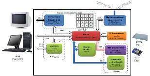
Fig. 6: Hardware architecture of the central node
Consequently, the system shows high level of flexibility to anticipate future needs and developments. As a result, the system would be customized to provide exactly the right access control for specific application with the ability of future upgrade of the system at the same high level performance and minimum cost.
Moreover, the central node provides debugging and communication interfaces. It has the ability to be connected to a personal computing device (laptop or desktop) either through either USB interface for further system development and firmware code modification or RS232 interface for potential visualization of the tracking information on the screen, allowing for proactively locating the employees within the enterprise. The hardware architecture of the central node is shown in Fig. 6.
6.3 The Door-Entry Node
In typical application of the proposed system, door-entry nodes are installed near the main entrance gates of the enterprise, office doors, and wherever user tracking is required to be maintained by the system. Door-entry nodes represent small and simplified version of the central node with respect to hardware architecture and code complexity. In contrast to the firmware of the central node, the firmware of the door-entry node includes neither system administration nor user configuration programmability session since the door-entry nodes depend on the central node automatically updating their local storage memory with the employees’ access rights database. The remote node comprises of the same 2.4GHz wireless ZigBee transceiver, XC-1A development card, real-time clock, and EEPROM of the central node. Besides, it contains relay control circuitry that automatically unlock an electric door strike if a specific employee is authenticated for access. The alphanumeric keypad that resides on the remote node is used by the employee at the main entrance gates of the enterprise to enter his assigned authorization password when prompted by the system after his RFID card is successfully authenticated for access. Authorization process is disabled within the enterprise and employees just need their RFID cards to be successfully granted access to the premises associated with their assigned access level. Fig. 7 shows the hardware architecture of the door-entry node.
IJSER © 2011 http://www.ijser.org
International Journal of Scientific & Engineering Research, Volume 2, Issue 12, December-2011 8
ISSN 2229-5518
6.4 Nodes Communication
In the proposed system, the central node takes the role of ZigBee coordinator while the door-entry nodes take the role of either ZigBee routers or end devices. The central node and the distributed door-entry nodes communicate using non-beacon enabled network, where every node that is participating in the network has the ability to transmit at any time the channel is open. The ZigBee coordinator, and probably the ZigBee routers, will have their radios continuously active, requiring a more robust power supply. The ZigBee module that resides on the central node may receive constantly, since it is connected to the mains supply, while the probably battery-powered door-entry nodes would remain asleep until either the sleep period is elapsed or an RFID tag is detected at the vicinity of the RFID reader that reside on that node. Upon wake-up, the door-entry node will poll its parent to see if there are any incoming messages from the central node waiting for it. These messages may be node configurations, updates of the employees’ access rights database, or simply status check of that door-entry node. On the other hand, once an RFID card is detected, the door-entry node wakes up and send a time- stamped access log entry of the recently authenticated employee to the central node. Fig. 8 depicts the flow diagram of the communication between the central node and the door-entry node.
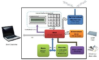
Fig 7: Hardware architecture of the door-entry node
7. Conclusion
In this paper, a novel of extended-features capabilities for the next-generation smart authentication and access control systems are introduced. The proposed system allows for not only limiting access to areas in a given physical facility just to authorized users, but italso provides the system administrator with configurable adaptive credibility and time schedule schemes, allowing for differentiating access rights to the same premises for different users. Moreover, the proposed system helps take control of the employees’ behaviour during working hours by keeping track of all their movement activities within the premises, allowing for
potential further evaluation of their performance and efficient salary pay system for companies.
The proposed system employs RFID technology, ZigBee wireless communication standard, and programmable chips from XMOS to achieve the designated purpose of the system. It delivers a working prototype, including the hardware and firmware, necessary to allow for further
development of the system.
Thanks to XMOS technology, yet the system has the
potential for more advanced features to be implemented and integrated to it that could meet the ultimate perspective security requirements, access options, and network topology. Moreover, the modular philosophy possessed by the proposed system allows it to be tailored to meet the ever differentiated customer needs in short time frames with efficient use of hardware components and minimized software development budget. As a result, each customer would be guaranteed to get his tailored-made cost-effective system that should be just good enough to cover his current requirements with the ability of future upgrades at the same high efficiency and low-cost level.
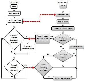
Fig. 8: Communication flow diagram between the central node and the door-entry node
References
[1] Committee on National Security Systems, “National Information Assurance (IA) Glossary,” CNSS Instruction No.
4009,http://www.cnss.gov/Assets/pdf/cnssi_4009.p df, viewed September 2011.
[2] Access Control & Security Systems Integration, “Reports Show Electronic Access Control, Biometric Sales To Grow,” July 2007, http://securitysolutions.com/news/electronics-sales- grow, viewed September 2011.
IJSER © 2011 http://www.ijser.org
International Journal of Scientific & Engineering Research, Volume 2, Issue 12, December-2011 9
ISSN 2229-5518
[3] Iman Morsi, Yasser Elsherief, and Amr El Zawawi,
“A Security System and Employees Performance
Evaluation Using RFID Sensors and Fuzzy Logic,” Future Computing, Service Computation, Cognitive, Adaptive, Content, Patterns, 2009. COMPUTATIONWORLD '09, Page(s): 597-602, DOI 10.1109/ComputationWorld.2009.112, 2009.
[4] Wang Yanyan, Zhao Xiaofeng, Wu Yaohua, and XuPeipei, “The research of RFID middleware’s data management model,” IEEE International Conference on Automation and Logistics, 2008, ICAL2008, Page(s): 2565 – 2568, DOI
10.1109/ICAL.2008.4636602.
[5] Zoghi B., Porter J., Jung Y., Thompson S., and Fink, Rainer, “Wireless Sensor Monitoring CombinedWith RFID Networks,” International Journal of Modern Engineering Conference, June 2006.
[6] Erick C. Jones, and Christopher A. Chung, “RFID in Logistics: A Practical Introduction,” CRC, Cleveland, OH, 2007.
[7] Landt J., “The history of RFID,” IEEE Potentials,
2005, Vol. 24, No. 4, Page(s): 8 – 11, DOI
10.1109/MP.2005.1549751.
[8] V. Daniel Hunt, Albert Puglia, and Mike Puglia, “RFID-A Guide to Radio Frequency Identification,” JohnWiley & Sons, 2007.
[9] B. Öztay, S. Baysan, and F. Akpinar, “Radio frequency identification (RFID) in hospitals,” Technovation, 2009, Vol. 29, No. 9, Page(s): 618-624.
[10] A. Nambiar, “RFID Technology: A Review of its Applications,” Proceedings of the World Congress on Engineering and Computer Science, WCECS
2009,Vol II,ISBN:978-988-18210-2-7, October 20-22,
2009, San Francisco, CA, USA.
[11] O. Shoewu, and O. Badejo, “Radio frequency identification technology: development, application, and security issues,” The Pacific Journal of Science and Technology, 2006, Vol. 2, No. 2,Page(s): 144-152.
[12] Savi Technologies, “Active and Passive RFID: Two Distinct But Complementary Technologies for Real- Time Supply Chain Visibility,” SAVI Technologies White Paper, 2002.
[13] Lionel M. Ni, Yunhao Liu, Yiu Cho Lau, and Abhishek P. Patil, “LANDMARC: indoor location sensing using active RFID,” Wireless Networks,
2004, Vol. 10, No. 6, Page(s): 701-710.
[14] Fagui Liu, Yang Zou, and Wenhui Liao, “Standard System Framework of RFID Application in Logistics,” Third International Symposium on Intelligent Information Technology Application,
2009, IITA 2009, Page(s): 44-47, DOI
10.1109/IITA.2009.288.
[15] Dong-Liang Wu, Ng, W.W.Y.,Yeung, D.S.,and
Hai-Lan Ding, “A brief survey on current RFID
applications,” International Conference on Machine
Learning and Cybernetics, 2009, Page(s): 2330 –
2335, DOI 10.1109/ICMLC.2009.5212147.
[16] Pala, Z., and Inanc, N., “Smart Parking Applications Using RFID Technology,”Proceedings of the First Annual RFID Eurasia Conference, 2007, Page(s): 1-
3, DOI 10.1109/RFIDEURASIA.2007.4368108.
[17] A. Reza, and T. Geok, “Investigation of Indoor Location Sensing via RFID Reader Network Utilizing Grid Covering Algorithm,” Wireless Personal Communications, 2009, Vol. 49, No. 1, Page(s):
67-80.
[18] Drew Gislason, “ZigBee Wireless Networking,”
Newnes,USA, 2008, ISBN-10: 0750685972,ISBN-13:
978-0750685979.
[19] Patrick Kinney, “ZigBee Technology: Wireless Control That Simply Works,” Communications Design Conference, October 2, 2003.
[20] SajdlOndrej, BradacZdenek, Fiedler Petr, and HyncicaOndrej, "ZigBee Technology and Device Design," International Conference on Networking, International Conference on Systems and International Conference on Mobile Communications and Learning Technologies, 2006, ICNICONSMCL'06, Page(s): 129.
[21] Robert Faludi, “Building Wireless Sensor Networks,”
O’Reilly Media, Inc., USA, 2011, ISBN: 978-0-596-
80773-3.
[22] ZigBee-Alliance, ZigBee specification, www.ZigBee.org, 2006.
[23] WheelerA., “Commercial Applications of Wireless Sensor Networks Using ZigBee,” IEEE Communications Magazine, 2007, Vol. 45, Issue 4, Page(s): 70-77, DOI 10.1109/MCOM.2007.343615.
[24] Ivan Howitt, andJose A. Gutierrez, IEEE 802.15.4 standard on low rate-wireless personal area network coexistence issues, IEEE, 2003, Page(s):
1481-1486,www.ieee.org.
[25] Ed Callaway, Paul Gorday, Lance Hester, Jose A.
Gutierrez, Marco Naeve, Bob Heile, and
VenkatBahl, “Home Networking with IEEE 802.15.4:
A Developing Standard for Low-Rate Wireless Personal
Area Networks,” IEEE Communications Magazine,
2002, Vol. 40, No. 8, Page(s): 70-77.
[26] Chaitanya S. Misal, “Analysis of Power Consumption of an End Device in a ZigBee Mesh Network,” University of North Carolina, Raleigh-Durham, NC, 2007, http://coe.uncc.edu/~jmconrad/GradStudents/Thesi s_Misal.pdf, viewed September 2011.
IJSER © 2011 http://www.ijser.org
International Journal of Scientific & Engineering Research, Volume 2, Issue 12, December-2011 10
ISSN 2229-5518
[27] JaejoonCho, and Sunshin An, “An Adaptive Beacon
Scheduling Mechanism Using Power Control in
Cluster-Tree WPANs,” International Journal of Wireless Personal Communications, 2009, Vol. 50, No. 2, Page(s): 143-160, DOI: 10.1007/s11277-008-
9581-3.
[28] Peter Bishop, “A Customizable Microcontroller as a Tradeoff between Microcontroller, DSP, FPGA and ASIC Technologies,” Atmel Corporation White Paper, 2009, http://www.atmel.com/dyn/resources/prod_docum ents/11002.pdf, viewed October 2011.
[29] ALTERA, “FPGA vs. DSP Design Reliability and
Maintenance,” ALTERA Corporation White Paper,
2007, http://www.altera.com/literature/wp/wp-
01023.pdf, viewed October 2011.
[30] XMOS Ltd, “XMOS Technology Whitepaper,” XMOS Ltd White Paper, 2010, https://www.xmos.com/download/public/XMOS- Technology-Whitepaper%281.0%29.pdf, viewed October 2011.
[31] XMOS Ltd, “A Programmable Revolution: A Compelling Alternative to Low Cost FPGAs,” XMOS Ltd White Paper, 2010, https://www.xmos.com/download/public/XMOS-
vs-FPGA-Whitepaper%281.0%29.pdf, viewed
October 2011.
[32] XMOS Ltd, http://www.xmos.com, viewed October
2011.
[33] XMOS Ltd, XCore Processor, http://www.xmos.com/technology/xcore, Viewed October 2011.
[34] Richard Terrill, XMOS Semiconductor, “Software- defined silicon: Why can't hardware be more like software?,” EETimes Design, 2008, http://www.eetimes.com/design/embedded/400754
2/Software-defined-silicon-Why-can-t-hardware-
be-more-like-software-?pageNumber=0, viewed
October 2011.
[35] David May, XMOS Semiconductor, “Software defined silicon is way ahead, says XMOS founder,” ElectronicsWeekly.com, 2008, http://www.electronicsweekly.com/Articles/18/01/2
008/42953/software-defined-silicon-is-way-ahead- says-xmos-founder.htm, viewed October 2011.
[36]
[37] David May, Ali Dixon, AyewinOung, and Henk
Muller, “XS1 System Specification,” Version 1.3,
XMOS Ltd, 2009, https://www.xmos.com/download/public/XS1-G- System-Specification%281.3%29.pdf, viewed October 2011.
[38]
[39] Peter Clarke, “XMOS fields software-defined
silicon,” 2007, Retrieved (n.d.) from
http://www.eetasia.com.
[40] Committee on National Security Systems, “National Information Assurance (IA) Glossary,” CNSS Instruction No. 4009, http://www.cnss.gov/Assets/pdf/cnssi_4009.pdf, viewed September 2011.
[41] S. D. Dissanayake, P. P. C. R. Karunasekara, D. D.
Lakmanaarachchi, A. J. D. Rathnayaka, A. T. L. K.
Samarasinghe, “Zigbee Wireless Vehicular Identification and Authentication System,” 4th International Conference on Information and Automation for Sustainability, 2008. ICIAFS 2008. Page(s): 257-260, DOI 10.1109/ICIAFS.2008.4783998,
2008.
[42] Wei J., Dan Y., Yan M., “A Tracking Algorithm in RFID Reader Network,”Frontier of Computer Science and Technology, 2006. FCST '06. Japan-China Joint Workshop, Fukushima, ISBN: 0-7695-2721-3, Page(s):
164-171, DOI 10.1109/FCST.2006.7, November 2006. [43] Rieback M.R., Crispo B., Tanenbaum, A.S., “The Evolution of RFID Security,” Pervasive Computing,
IEEE, Vol.5 (1), Page(s): 62-69, DOI
10.1109/MPRV.2006.17, March 2006.
[44] H. M. Tsai, C. Saraydar, T. Talty, M. Ames, A.
Macdonald, O. K. Tonguz, “Zigbee-based intra-car
wireless sensor network,”ICC ’07, IEEE International
Conference, Page(s): 3965–3971, June 2007.
[45] ImanMorsi, Yasser Elsherief, Amr El Zawawi, “A Security System and Employees Performance Evaluation Using RFID Sensors and Fuzzy Logic,”Future Computing, Service Computation, Cognitive, Adaptive, Content, Patterns, 2009. COMPUTATIONWORLD '09, Page(s): 597-602, DOI
10.1109/ComputationWorld.2009.112, 2009.
[46] S. S. RiazAhamed, “The Role of ZigBee Technology in Future Data Communication System,”Journal of Theoretical and Applied Information Technology, Vol.5, No.2, 2009.
[47] StanislavSafaric, KresimirMalaric, “ZigBeewireless standard,” 48th International Symposium ELMAR-
2006, Zadar, Croatia, 2006.
[48] Douglas Watt, 2009, “Programming XC on XMOS Devices,”XMOS Ltd, http://www.xmos.com/technology/xc, viewed September 2011.
[49] Wikipedia: The Free Encyclopedia, Wikimedia Foundation Inc., "Bit banging," http://en.wikipedia.org/wiki/Bit-banging, viewed June 2011.
IJSER © 2011 http://www.ijser.org
International Journal of Scientific & Engineering Research, Volume 2, Issue 12, December-2011 11
ISSN 2229-5518
[50] Z. Wu, H. Chu, Y. Pan, X. Yang, “Bus priority
control system based on wireless sensor network
(WSN) and zigbee,”Vehicular Electronics and Safety,
2006. ICVES 2006. IEEE International Conference,
Page(s): 148–151, Dec. 2006.
[51] XMOS Ltd, 2010, “A Programmable Revolution: A Compelling Alternative to Low Cost FPGAs,” https://www.xmos.com/download/public/XMOS-
vs-FPGA-Whitepaper%281%29.pdf, viewed
September 2011.
[52] XMOS Ltd, 2010, “XMOS Technology Whitepaper,” https://www.xmos.com/download/public/XMOS- Technology-Whitepaper%281%29.pdf,viewed September 2011.
[53] ZigBee Alliance, FAQ, “What is the advantage of the ZigBee solution over proprietary solutions?”
http://www.zigbee.org/About/FAQ.aspx#28, viewed September 2011.
IJSER © 2011 http://www.ijser.org