𝑞� 𝑉��
International Journal of Scientific & Engineering Research, Volume 4, Issue 6, June-2013
ISSN 2229-5518
3055
Altaf H. Nizamani1, Bilal Rasool2, M. Tahir2,3, Nek M. Shaikh1, Hussain Saleem4
1University of Sindh, Jamshoro, 76080, Pakistan
2University of Sargodha, Sargodha, 40100, Pakistan
3King Abdullah University of Science and Technology, Thuwal, 23955-6900, K. S. Arabia
4University of Karachi, Karachi, 75270, Pakistan
ABSTRACT : Effective and efficient trapped ion transportation operations are important for many quantum information implementations. In this report, we provide an efficient shuttling protocol for the linear shuttling of ions in asymmetric surface trap geometries in which outer electrode is segmented to provide control over ion transportation from one trapping region to other trapping region. During the adiabatic shuttling operations, the maximum transportation speed of trapped ions depends on the trapped ion’s secular frequencies during the process. We show how adiabatic linear shuttling protocols can be implemented in optimised surface trap geometries. In order to make the shuttling process adiabatic, the important parameters that need to be taken into account, are also discussed.
Keywords – Ion traps, ion shuttling, optimum traps, quantum computation, quantum information.
In the last decade, considerable work has been done towards building scalable architectures to
implement quantum information processing with trapped ions [1,2,3]. The focus is on microfabricated surface trap arrays where the ions are trapped above the surface of a planar trap structure. For the effective quantum operations, it is suggested if ions can be trapped in separate trapping zones and when quantum operations are required, they can be brought together in a single trapping region (processor zone) [4,5,6]. Shuttling process has been demonstrated successfully in linear trap arrays and through T and Y-junctions [7,8,9]. Optimisation of electrode geometries has been discussed by Home and Steane [10]. The energy gain of trapped ions during shuttling operations is discussed by Hucul et al. [11] and Reichle et al. [12]. We combine their useful findings and implement them to examine the linear ion shuttling process in surface trap arrays. We also provide a description of how such arrays need to be optimised to allow for efficient and adiabatic shuttling. Furthermore, we provide a detailed analysis of the dynamics of the process by solving the equations of motion and present a discussion about the considerations that can be taken in account to make the shuttling process adiabatic in outer- segmented geometries. The trap geometries can be categorised in two types, asymmetric ion traps and symmetric ion traps. In asymmetric traps, the electrodes lie in a plane and the ions are trapped above that plane, and in symmetric trap designs, the electrodes are symmetrically placed around the position of the trapped ion. Asymmetric traps are known as planar or surface traps and symmetric traps are known as multilayer traps. The main advantage of the planar trap configuration is its ability to be expended to large arrays, in order to construct a quantum computer. Here, we discuss the dynamics of the linear shuttling process in realistic trap arrays. We also present a guide to accomplish efficient, adiabatic and fast ion transportation in one-dimension.
Designing of an optimised basic element of surface trap arrays where ions can be trapped by applying
appropriate voltages on the trap electrodes with a maximum trap depth at a given ion-electrode distance is discussed in [13,14]. In a typical three-dimensional linear rf Paul trap, the rf field provides trapping in the radial axes (x and y-directions) whereas a dc potential provides confinement in the axial direction (z-direction). The effective trapping potential in all three directions is given by [11],
2 2
Ψ(𝜒, 𝑡) =![]()
𝑞� 𝑉��
2 |∇θrf (χ)|2 + 𝑞� ∑ 𝑉𝑛 (𝑡)𝜃𝑛 (𝜒)
4���
(1)
𝑛
where, m and qe are the mass and charge of the trapped ion. χ is the position vector. Θrf (χ) is the instantaneous
electric rf-potential. Θn(χ) is the dc potential produced by the nthdc electrode when Vn = 1 V. The peak rf-voltage Vrf is applied on the rf-electrodes with drive frequency Ωrf and the coefficient Vn(t) is the time varying voltage applied on the n th control electrode. A pseudopotential provided by the rf electrodes are represented in the first part of Eq. 1. The position of the rf-node or minimum of the pseudopotential where the ions can be trapped is
illustrated in Fig. 1, where h is the ion – electrode distance (ion-height) above the surface of the trap in the y-
direction and xo is the position of the ion in the x-direction. The escape point of the ion is located above the
IJSER © 2013 http://www.ijser.org
International Journal of Scientific & Engineering Research, Volume 4, Issue 6, June-2013
ISSN 2229-5518
3056
Adiabatic ion shuttling protocols in outer-segmented-electrode surface ion traps
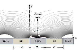
trapping position. The labels b and c in Fig.1 represent widths of the electrodes whereas a is separation between the rf-electrodes. The analytical model suggested by House [13], can be used to calculate the basis functions for the trap electrodes.
Figure 1. The pseudopotential above the surface trap electrodes. Xo is the horizontal position of the ion, h is the height of a trapped ion. The escape point for the ion is located beyond h. b and c are the widths of the rf electrodes whereas a is the distance between the rf electrodes.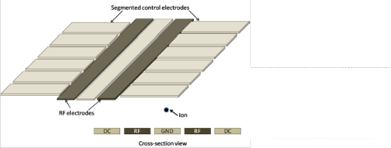
The trapped ion(s) can be confined and shuttled in the z-direction by applying and varying dc voltages on the segmented electrodes. In order to reduce the heating of the trapped ion during its shuttling process, the width of a segmented electrode w should be chosen in a way that the trapping field has a significant curvature everywhere along the transportation path of the ion near the electrode [13]. Therefore, for the trap design shown in Fig. 3, outer segmented electrode widths may be chosen as(w=4a). To avoid diffraction effect of the laser lights from the trap surface and anomalous heating, ions have to be trapped above the surface electrodes at larger ion-electrode distance but this decreases the trap depth. The optimised trap design suggested by [13,14] reduces this effect.
Figure 2. Planer or surface rf trap geometry. Axial confinement is implemented with outer-segmented electrodes. Trapped ion location is illustrated in cross section view of the design
The adiabatic shuttling protocol is described as transportation of the ions in the arbitrary locations within the trap array without significantly manipulating the motional state of the ions. Hucul et al. [11] and Reichle et al. [12] have shown the importance of shuttling protocols using functions. Hucul et al. described the advantages of the hyperbolic tangent profile;
𝑃ℎ𝑦𝑝 (𝑡) = tanh[𝑁![]()
�−𝑇] (2)
𝑇
In equation (2), T is the total shuttling time whereas t is the instantaneous shuttling time. The larger values of N
produce more gradual changes for values of t near to 0 and T, while incorporating larger rates of change for values of t near to T/2. By using the basis functions for individual electrodes, an arbitrary time dependent potential can be created. The classical equations of motion can be utilised to calculate the force on a charged
particle [11];
2 | Page
IJSER © 2013 http://www.ijser.org
International Journal of Scientific & Engineering Research, Volume 4, Issue 6, June-2013
ISSN 2229-5518
3057
Adiabatic ion shuttling protocols in outer-segmented-electrode surface ion traps
3
∑ �𝜒𝑛 + ∇n ψ(χj , t) = 0
𝑛
(3)
where the pseudopotential Ψ(χj , t) is defined in Eq. 1j. the ion trajectories can be calculated by solving Eq. (3)
numerically. The ion dynamics in the x, y and z directions as a function of time t can be calculated by getting highly accurate solutions of Eq. (3). The solutions can also be used to calculate the kinetic energy gained by the ion. In order to solve these differential equations, we use a Mathematica-7 package called “NDSolve”.
III.1 Average motional energy
In a quantum harmonic oscillator of frequency ωo, the average energy ⟨E⟩ of level ⟨n⟩ is given by ⟨𝐸⟩ =![]()
ℏ𝜔(⟨�⟩ + 1). The average motional quanta ⟨n⟩ for a trapped ion can be calculated as;
2
![]()
1 �𝑣2
⟨�⟩� = ℏ𝜔
(4)
where vt is the maximum velocity, m is the mass of the ion and ωt is the instantaneous secular frequency. In the frame of the pseudopotential well, the kinetic energy of the ion is only due to its secular motion. The maximum kinetic energy of the ion at the beginning and end of the shuttling process can be obtained by plotting the kinetic energy of the ion as a function of the shuttling time. Therefore, the average motional state change of the shuttled ion is;
⟨n⟩s =![]()
Final K. E(max) − Ininial K. E(max)
ℏωt
(5)
where, K.E(max) is the maximum kinetic energy of the ion in a potential well.
III.2 Motional heating caused by anomalous heating
The motional excitation of an ion during shuttling process can be caused by anomalous heating due to small ion-
electrode distance in the trap. It is experimentally shown that the heating rate ⟨n⟩an is related to the ion-electrode
distance and scaled to h4 and to the secular frequency scaling as ω2[15]. A conservative approximation of the
motional state excitation of the Yb+ due to anomalous heating is carried out by [15] provide a realistic estimate;
1.97 ± 0.5 × 1026 𝜇�4 Hz3
⟨�⟩𝑎𝑛 ≈![]()
𝜔2 ℎ4 , (6)
where ω is in units of s-1 and h is ion – electrode distance in units of micrometres. This expression is only valid
for the particular ion trap and ion specie it was measured for. However it still provides a reasonable estimate of heating rate for illustration purposes. We note the optimisation of electrode surfaces and materials can
substantially reduce heating rate. During the shuttling process, the motional quanta ⟨n⟩an gained from the anomalous heating, can be calculated by integrating ⟨n⟩an over the shuttling time [14];
�𝑓
⟨�⟩𝑎𝑛 = ∫ ⟨�⟩𝑎𝑛 𝑑𝑡 (7)
�𝑜
where, to and tf are the beginning and the ending time for a shuttling process. The integral in Eq. 7 also takes into
account the changing secular frequencies ωz during the shuttling process [14]. Hence, the total number of the
motional quanta ⟨n⟩ can be calculated as;
⟨�⟩ = ⟨�⟩� + ⟨�⟩𝑎𝑛 (8)
In order to demonstrate the importance of optimal trap geometries for ion transportation, it is useful to analyse
the actual ion dynamics during the shuttling process. We obtained actual simulations for a given set of example parameters but the conclusions obtained in this section are applicable for wide range of trap geometries featuring different ion - electrode distances.
The optimisation of the trap electrodes for the maximum κ and β parameters are investigated in Sec.II. These two important parameters provide maximum trap depth and secular frequency during the shuttling process. A set of actual values of κ and β are needed to carry out simulations of the ion dynamics during
3 | Page
IJSER © 2013 http://www.ijser.org
International Journal of Scientific & Engineering Research, Volume 4, Issue 6, June-2013
ISSN 2229-5518
3058
Adiabatic ion shuttling protocols in outer-segmented-electrode surface ion traps
shuttling process. For this, we need a realistic set of electrode voltages that can be applied to the trap. The trap depth σ and the rf trap stability factor q are related as;
𝑉��![]()
σ = 2𝜋 2
2 2
𝜅𝑞 (9)
where 𝑞 = 2𝑞� 𝑉�� /(�Ωrf ℎ ) .
Limited set of voltages can be applied on microfabricated ion traps due to voltage breakdown via insulator bulk
and surfaces. Therefore, in order to achieve a deep trap, one should choose q as large as possible without getting out of the region of stability in parameter space. Therefore, the value of q, near to 0.7 seems a reasonable choice. Another important parameter to be considered is the power dissipation within the ion trap which can lead to destruction of the chip. The Power dissipation Pd of a trap having capacitance C and resistance R, can be estimated as [17];
2 2 2
𝑃� ≈ 0.5𝑉�� Ωrf C R (10)
Power dissipation of ≈ 3W normally do not lead to a large temperature change in typical ion trap chips.
We considering a typical microfabricated chip having electrodes made of electroplated gold on a commercially available Silicon Oxide (SiO2) insulator wafer [18]. The thickness of the electrodes is considered to be ≈15μm. In such traps, we can estimate typical values of R ≈ 0.5Ω and C ≈ 20pF for the resistance and capacitance respectively. Assuming Ωrf ≈2π × 55MHz for the above trap, one could safely apply Vrf of approximately 460 −
500 V by setting q ≈ 0.7. These values are estimated to trap an 171Yb+ ion. The power dissipation for this trap can be calculated as Pd < 3W. In order to avoid damaging the chip, we limit voltage difference between
adjacent electrodes near to 500V.
In order to feature acceptably low motional excitation due to anomalous heating during the shuttling we take an ion - electrode distance sufficiently large. For this reason, here we select an ion - electrode distance of ≈
80μm. For an example, a trap depth of ≈ 0.35eV and radial secular frequencies (ωx and ωy) of up to ≈4.4MHz for an 171Yb+ ion can be easily be achieved in the trap by using the trap parameters mentioned above. Once ion - electrode distance above the surface is chosen, all other electrode dimensions are determined accordingly. For principal axis rotation, assuming unequal rf electrodes (b = c/2), optimum widths are therefore b ≈ 300μm and c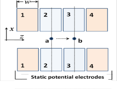
≈ 150μm. The electrodes can be separated by a ground electrode of width 50μm (i.e. the separation between rf electrodes is a = 60μm including 5μm gap between rf-electrodes and the ground electrode). As discussed earlier, for the design shown in 3 the optimum widths for the control electrodes are then to be W = C = E ≈ 220μm. For an exemplary trap geometry, we refer to an outer segmented design shown in (Fig. 3) following the constraints and dimensions explained above. In order to calculate the overall motional excitation, we solve the equations of motion for the shuttled ion. The end results provided in this report are obtained for the particular trap parameters stated above, still we believe, conclusion obtained is applicable for many surface trap arrays.
Figure 3. Trapping zone ‘a’ to ‘b’ in z-direction.
4 | Page
IJSER © 2013 http://www.ijser.org
International Journal of Scientific & Engineering Research, Volume 4, Issue 6, June-2013
ISSN 2229-5518
3059
Adiabatic ion shuttling protocols in outer-segmented-electrode surface ion traps
III.3 Ion shuttling in the outer segmented trap
In the case of outer-segmented trap geometries (discussed above), an ion can be confined in the z- direction by using at least 6 control electrodes. Therefore, to produce two adjacent trapping zones along the rf nodal path (axial direction), it requires minimum 8 control electrodes. The trapping zones ‘a’ and ‘b’ in such geometries are shown in Fig. 3. Here the radial confinement is provided by rf electrodes (rf electrodes are not shown in the figure). To ensure symmetry in the radial direction, opposite facing control electrodes are connected to the same voltage supply. The rf voltage is set to Vrf = 450 V with a driving frequency of Ωrf = 2π
52MHz and dc voltages are limited to ±50 V, as we discussed voltage constraints set in section 3. By applying the above voltages, the secular frequencies in x and y directions can be calculated as ωx ≈ ωy ≈ 4MHz and the trap depth is ≈ 0.35eV.
The basis functions for the control electrodes can be calculated using analytical method suggested by House [13]. All the other required parameters of the trap then can be calculated using Mathematica software. The voltages on the endcap control electrodes (1 and 3) for trapping zone ‘a’ are first set to some arbitrary value and then the required voltage on electrode 2 is calculated to keep the ion at the rf node position. In the second stage, all the voltages are scaled iteratively until a desired value of a secular frequency (ωo/2π) in the z-direction is obtained. The same calculation process is repeated to obtain a set of voltages for the trapping zone ‘b’. In an optimum trap geometry shown in Fig. 3, to see the effect of N-parameters of hyperbolic tangent time profile (discussed above) with different shuttling times, the ramping profile of the voltages (shown in Fig. 4) are applied with N-parameter of N = (2.6, 3.0, 3.4) values to shuttle an ion from zone ‘a’ to ‘b’. At the start of the shuttling protocol, electrodes 1, 3 and 4 are held at +26 V and electrode 2 initially at -50 V. The secular frequency ωo in the z-direction in trapping zone ‘a’ is calculated to be approximately ≈ 500kHz. In order to move the ion from zone ‘a’ to zone ‘b’, the voltage on electrode 2 has to be brought to +26 V and the voltage on electrode 3 has to be brought to -50 V, monotonically in time t. The ion will be moved to trapping zone ‘b’ form initial trapping zone ‘a’ after the completion of the voltage ramps. The secular frequency remains the same in both trapping zones. By following the voltage ramp profile given in Fig. 4, the ion is successfully shuttled a distance of ≈ 225μm from zone ‘a’ to ‘b’. A typical ion trajectory in the z-direction is shown in Fig. 5 when the
dc voltage change with the hyperbolic tangent time profile is applied. The average motional quanta ⟨n⟩ are
plotted against the shuttling periods which are scaled with the secular frequency ωo and represented in number
of cycles (Tωo/2π) in the horizontal axis in Fig. 6. Here, it can be learnt from the plots that the gain of the
average motional quanta ⟨n⟩s of the ion is reduced with larger shuttling time but on the other side, the longer shuttling periods add more quanta from the anomalous heating source. Hence the cross over points for ⟨n⟩s gained by following the particular hyperbolic tangent N-parameter plots (solid lines) and the ⟨n⟩an (dashed line) set the lower limit of the total average motional quanta ⟨n⟩ gained by the ion during the shuttling. Further to
this, it can be seen in Fig. 6 that the hyperbolic tangent parameter N = 3.0 adds less quanta at the cross over
point than the N = 2.6 or N = 3.4 and also provides shorter shuttling times.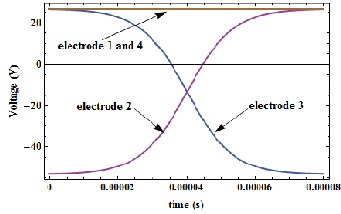
Figure 4. The voltage variation in time to move the trapped ion from the trapping zone ‘a’ to ‘b’. The hyperbolic tangent time profile is used.
5 | Page
IJSER © 2013 http://www.ijser.org
International Journal of Scientific & Engineering Research, Volume 4, Issue 6, June-2013
ISSN 2229-5518
3060
Adiabatic ion shuttling protocols in outer-segmented-electrode surface ion traps
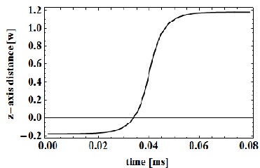
Figure 5. The distance shuttled by the ion when the dc voltage change with a hyperbolic tangent time profile is applied. The shuttled distance in z- direction is normalised with the width of the electrode w.
Figure 6. The gain in the average motional quanta ⟨n⟩ by the ion in a centre segmented trap geometry after
the shuttling of the ion from trapping zone ‘a’ to ‘b’ following the hyperbolic tangent time profile of N =
(2:6; 3:0; 3:4) versus shuttling time scaled with secular frequency ωo/2π = 500 kHz. The solid lines
represent the best fits of motional quanta ⟨n⟩s and the dashed line shows the gain of ⟨n⟩ an from the anomalous heating of the trap. The cross over points set lower limits for the gain in ⟨n⟩ during the shuttling
process.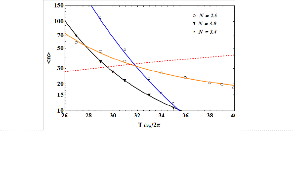
Using realistic trap geometry in our considerations, we learn a lot about optimal trap designs by analysing the
actual dynamics of the ion transportation process. Given that the presence of anomalous heating in the traps caused by fluctuating and stray charges on the trap electrodes, the conclusion from our results show that optimal geometries should be a prerequisite to ensure adiabatic shuttling. We have demonstrated the role of optimum trap geometries for efficient fast ion shuttling in scalable surface ion traps. It is known that, a shuttling pro-
cess adds less energy to the ions if performed under higher secular frequencies. By optimisation of the electrode dimensions, the secular frequencies (ωz) during the shuttling process can be maximised. The secular frequency depends upon two important trap parameters α and β. By analysing a realistic microfabricated trap design, we have solved the equations of motion for the dynamics of ion shuttling and illustrated the importance of optimised electrode configurations in outer segmented trap geometries. The outer segmented design can
be a geometry of choice due to the much simpler fabrication process.
6 | Page
IJSER © 2013 http://www.ijser.org
International Journal of Scientific & Engineering Research, Volume 4, Issue 6, June-2013
ISSN 2229-5518
3061
Adiabatic ion shuttling protocols in outer-segmented-electrode surface ion traps
[1] J I. Cirac and P. Zoller. Quantum computations with cold trapped ions. Phys. Rev. Lett. 74, 1995, 4091
[2] C. Monroe. Quantum information processing with atoms and photons. Nature 416, 2002, 238.
[3] H. Haffner, C. F. Roos, and R. Blatt. Ion trap quantum computing with Ca+ ions. Physics Reports 469, 2008, 155
[4] D. J. Wineland, C. Monroe, W. M. Itano, D. Leibfried, B.E. King, and D.M. Meekhof. Experimental issues in coherent quantum-state manipulation of trapped atomic ions. J. Res. Natl. Inst. Stand. Technol, 103, 1998, 259
[5] J. I. Cirac and P. Zoller. A scalable quantum computer with ions in an array of microtraps. Nature, 404, 2000, 579
[6] D. Kielpinski, C. Monroe, and D. J.Wineland. Architecture for a large-scale ion-trap quantum computer. Nature, 417, 2002, 709 [7] W. K. Hensinger, S. Olmschenk, D. Stick, D. Hucul, M. Yeo M. Acton, L. Deslauriers, C. Monroe, and J. Rabchuk. T-junction
ion trap array for two-dimensional ion shuttling, storage, and manipulation Appl Phys. Lett., 88, 2006, 034101
[8] S. Schulz, U. Poschinger, K. Singer, and F. Schmidt-Kaler. Optimization of segmented linear Paul traps and transport of stored particles. Fortschr. Phys., 54, 2006, 648
[9] J. M. Amini et. el. Toward scalable ion traps for quantum information processing. New Journal of Physics, 12, , 2010, 033031 [10] J. P. Home and A.M. Steane. Electrode configurations for fast separation of trapped ions. Quant. Inf. Comp., 6, 2006, 289
[11] D. Hucul, M. Yeo,W. K. Hensinger, J. Rabchuk, S. Olmschenk and C. Monroe. On the transport of atomic ions in linear and multidimensional ion trap arrays. Quant. Inf. Comp., 8, 2008, 0501
[12] R. Reichle, et. el Fortschr. Transport dynamics of single ions in segmented microstructured Paul trap arrays. Phys., 54, 2006, 666 [13] M. G. House. Analytic model for electrostatic fields in surface-electrode ion traps. Phys. Rev. A, 78, 2008, 033402
[14] Altaf H. Nizamani, and Winfried K. Hensinger. Optimum electrode configurations for fast ion separation in microfabricated surface ion traps, Applied Physics B, 106,2012, 2
[15] L. Deslauriers, S. Olmschenk, D. Stick, W. K. Hensinger J. Sterk, and C. Monroe. Scaling and suppression of anomalous heating in ion traps. Phys. Rev. Lett., 97, 2006, 103007
[16] James J. McLoughlin, Altaf H. Nizamani, James D. Siverns Robin C. Sterling,et.el. Versatile ytterbium ion trap experiment for operation of scalable ion-trap chips with motional heating and transition-frequency measurements. Phys. Rev. A, 83 , 2011,
013406
[17] M. D. Hughes, B. Lekitsch, J. A. Broersma, and W. K Hensinger. Microfabricated Ion Traps. arXiv:1101.3207v2, 2011
[18] S. Seidelin, et. el. Microfabricated surface-electrode ion trap for scalable quantum information processing. Phys. Rev. Lett., 96,
2006, 253003
7 | Page
IJSER © 2013 http://www.ijser.org