International Journal of Scientific & Engineering Research, Volume 3, Issue 2, February-2012 1
ISSN 2229-5518
Accident Analysis of Narora Fire Accident
G DivyaDeepak
—————————— ——————————
(TB) and through cables into the Control Equipment Room
(CER), where fire barriers had given way. There was heavy
ingress of smoke into the control room, mainly through the intake of ventilation system, forcing the operators to vacate the control room. Loss of indications due to burning of control cables rendered the supplementary control room also
March 31, 1993 saw an event, which caused a significant change in the manner in which issues of potential
for common cause failures and quality assurance were approached by AERB and also significantly altered the style of regulatory functioning of AERB. The event involved a major fire in the turbine building of NAPS unit-1, that resulted in a total loss of power to the unit for over 17 hours[10].The incident was initiated by failure of two turbine blades in the last stage of the low pressure turbine, which resulted in severe imbalance in the turbo- generator leading to rupturing of hydrogen seals and lube oil lines, leading to fire. The fire spread to several cable trays, relay panels, etc., in a short duration. The operating crew responded by tripping the reactor by manual actuation of primary shutdown system within a minute of the turbine failure and also initiated fast cool down of the reactor[4]. The fire had spread through the generator bus duct in the Turbine Building
G. Divya Deepak is currently working as an Assistant Professor in Nuclear Engineering Department at Mody Institute of Technology and Science(Deemed University),(Lakshmangarh) Rajasthan India.Phone no-91-
1573-225001(off),09694836381(Personal)
Email-divyadeepak77@gmail.com
unusable. There was widespread damage to the power cables
as well as the control cables. Hence, even though the power sources were available, neither the power supply from the grid nor from the 101 diesel generators or from the batteries was available to the essential equipment. This resulted in a complete loss of power supply in the Unit after about 7 minutes of the incident that continued for a period of 17 hours. During this long blackout, operators injected firewater into the secondary side of Steam Generators, with the objective of removal of decay heat from the core through thermo-siphoning in the primary side. There was no radiological impact of the incident. The major fire was put out in about 90 minutes. The event was rated in the INES Scale at level-3, mainly on account of the degradation of defense - in depth of engineered safety features during the incident. This was one of the most serious events that the Indian nuclear industry came across till date.
Root cause analysis (RCA) is a class of problem solving methods aimed at identifying the root causes of problems or incidents. The practice of RCA is predicated on the belief that problems are best solved by attempting to correct or eliminate root causes, as opposed to merely addressing the immediately obvious symptoms. By directing corrective measures at root causes, it is hoped that the likelihood of problem recurrence will be minimized. However, it is recognized that complete prevention of recurrence by a single intervention is not always possible. Thus, RCA is often considered to be an iterative process, and is frequently viewed as a tool of continuous improvement. RCA,[1] initially is a reactive method of problem detection and solving.
IJSER © 2012 http://www.ijser.org
International Journal of Scientific & Engineering Research, Volume 3, Issue 2, February-2012 2
ISSN 2229-5518
RCA[1] is a separate process to Incident Management. In root cause analysis we classify the events into three categories namely
2.1 Root cause.
Root cause is defines as the cause which if prevented would have prevented the event.
2.2 Direct cause.
Direct cause is defined as the immediate precursors which caused the event.
2.3 Contributing cause.
Contributing cause is defined as the cause which increased the likelihood of the event.
Figure 1

Here in the case of Narora the root cause which we found from our analysis is the rupture of turbine blades , this is the event which initiated the accident and if it had been avoided the whole accident wouldn’t have occurred .The main reason for the occurrence of rupture of turbine blades is the accumulation of stress on the blades [2], this event occurred at 0 milli sec .The event first initiated with the rupture of two blades in the LP turbine and which snapped the other sixteen blades located in the LP turbine ,due to which the angular momentum of the blades changed and the accumulated stress on the blades started to produce vibrations in the turbine blades. The hydrogen gas which is the coolant to the turbo generator is passed through the pipe. Due to the vibrations caused in the blades the hydrogen gas leaked from the pipe, and that got contact with the vibrating
38 sec rupturing of hydrogen seals
40 sec rupturing of
lube oil lines
contributing cause
contributing
cause
vibrations in the
generator unit vibrations in
the
hydrogen is highly inflammable gas. The rupturing of the hydrogen seals is the contributing cause, since this cause increases the likelihood of the event. This event occurred at
got in contact with the oil, which was to be supplied to the generating unit for lubrication purposes. The oil tank was placed above the turbine and it was used for lubrication by
1m
20sec
3m
24sec
fire spread through
the generator bus duct in
the turbine
building (tb) and through cables into the control equipment room (cer)
power cables burning
direct cause lubricating oil
as a medium of transport
root cause lack of fire resistant
insulation
the generator unit[9]. The spark got in contact with the oil,
due to the rupturing of the oil tanks caused by increase in the vibrations of the turbine blades[3], fire was produced and it propagated throughout the turbine building and got exploded. The smoke that was produced at that time got spread in the control room via the ventilations provided in the control room and the operators working were suppose to leave the place immediately[5]. This is the another contributing cause, which increased the likelihood of the event. This event occurred at the time of 40 sec after the event had started. The fire even spread through the generator bus duct in the Turbine Building (TB) and through cables into the Control Equipment Room (CER). The reason for the spreading of the fire is due to lubricating oil which acted as a medium of transport due to which it exploded. This event is considered as the direct cause .
ER © 2012
negligence of the | root cause | ……………… …….. |
International Journal of Scientific & Engineering Research, Volume 3, Issue 2, February-2012 3
ISSN 2229-5518
.The burning of the power cables could have been avoided if the insulation would have been made with fire resistant materials. If this event wouldn’t have occurred then the turbine building wouldn’t have exploded .So we consider this also as a root cause since this initiated the fire to spread and if this event would have been prevented then the accident wouldn’t have occurred. This event occurred at 3 M
24 sec, which is recorded at the time of the event.
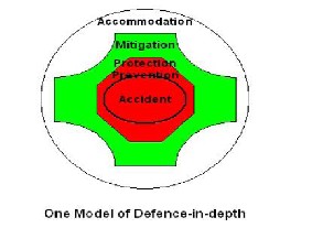
In nuclear engineering and nuclear safety, defense in depth denotes the practice of having multiple, redundant, and independent layers of safety systems for the single, critical point of failure: the reactor core. This helps to reduce the risk that a single failure of a critical system could cause a core meltdown or a catastrophic failure of reactor containment.
The above figure 1 shows the various parameters that need to be considered when an accident is the event. That is for the nuclear accident does the reactor have:
With respect to Narora fire accident the following mechanisms support the defense in depth concept.
3.1Preventionmechanism
3.1.1 Process Water
Here the process water was successful in providing
continuous cooling and prevented the fuel from melt down and also prevented the collapse of the fuel channels[6].
3.1.2 Backup Heat Sinks
They functioned properly and resulted in continuous heat removal from the coolant and ensured the safety of the reactor and prevented fuel meltdown.
3.1.3 Safety Valves.
Here venting was successful and it ensured that there was proper air circulation and prevented any damage to the equipments.
Here safety valves functioned properly and all the
parameters like (pressure, temperature) were kept under control and there was leakage of any coolant[8].
3.1.4 Control systems.
Here the control system such as shut off rods and secondary shut down system functioned properly and ensured safe shut down of the reactor without core meltdown.
3.1.5 Feedback Systems.
Here the feedback systems functioned properly and ensured the continuous coolant circulation[3] .The temperature and pressure of all the other components were kept below the safety limit.
3.1.6 Primary heat transport system.
The PHT functioned successfully and ensured continuous cooling of the fuel and prevented fuel meltdown.
3.1.7 Trained and skilled personnel.
Here the people were trained and skilled personnel as they followed the required safety procedure and ensured the safe shut down of the reactor without any release of radio activity to the environment.
3.2 Protection mechanism
3.2.1 External Natural Disasters
3.2.2 Trip Systems
Trip systems functioned properly and ensured the all the safety systems were turned on at appropriate stages when they were needed; as a result all the safety systems functioned properly and prevented any failure of safety systems.
3.3.3 Shut down systems.
The shutdown systems shutoff rods & secondary shut down system functioned successfully and ensured that there was core no meltdown & no release of radio activity.
3.3.4 ECCS.
3.3.5 Containment building.
This functioned successfully by ensuring that no release of radio activity to the surroundings.
3.3.6 Automatic system Responses
Automatic system responses were good as they were activated at the right time and functioned properly to ensure proper shutdown of the reactor, thereby preventing fuel damage and core meltdown.
3.4 Mitigation mechanism
3.4.1 Venting.
3.4.2 Dedicated heat removal Chain.
Here the dedicated heat removal chain was successful in as the primary coolant removed heat from the fuel continuously and heat from the primary coolant was removed by the secondary coolant continuously thereby ensuring continuous heat removal as a dedicated heat removal chain.
IJSER © 2012 http://www.ijser.org
International Journal of Scientific & Engineering Research, Volume 3, Issue 2, February-2012 4
ISSN 2229-5518
3.1.6 Large Fire Water for Emergency purpose.
3.1.7 External Warnings.
3.1.8 Off Site Responses.
3.5 Accommodation mechanism
3.5.1 Post Shutdown Heat Removal System.
3.5.6 Valves for injection of POISSONS.
3.5.7 External Fire Extinguishers
As mentioned above, the various systems that were present
and support the defense in depth are mentioned. We see that
the ones marked in red color signify that they are absent and due to which the severity of the accident increased. If the mechanisms that are marked in red are present, there would have been chances where the accident would or might have been less effective.
4.1 Large fire water system
Here the large fire water system was absent and there was shortage of water when the fire in the turbine building was to be extinguished and hence the personnel had to call the fire department for additional supply of water and this delay in extinguishing the fire due to shortage of water supply resulted in large damage to the turbine building.
4.2 External warnings
These external warning systems had also failed since they
were not specific in nature, that is during the accident since large number of alarms were seen the operating personnel could recognize it and there was delay in taking the required safety action, this delay resulted in further damage of the turbine building.
4.3 Accommodation
4.3.1 POST SHUTDOWN HEAT REMOVAL SYSTEMS
These systems were successful since they operated properly and ensured safe shut down of reactor by shutdown cooling system. This secondary shutdown system ensured that there was continuous decay heat
removal from the fuel after shutdown and thus prevented the fuel damage to a large extent.
3.4.3 VALVES FOR INJECTION OF POISON
The valves for injection of boron poison also were successful since they ensured that the boron was dropped into the reactor core for complete shutdown and prevented the reactor from attaining second criticality[8].
5. TOP-BOTTOM APPROACH-
In a top-down approach an overview of the system is first formulated, specifying but not detailing any first-level subsystems[7]. Each subsystem is then refined in yet greater detail, sometimes in many additional subsystem levels, until the entire specification is reduced to base elements.
6.1. Redesign of turbine blades.
This includes increasing the thickness of the turbine blades and
the convexity of the turbine blades. The reason for this being Increased convexity avoids back-rake stress reduction. Thus we have less chances of stress accumulation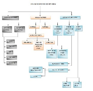
Figure2
IJSER © 2012 http://www.ijser.org
International Journal of Scientific & Engineering Research, Volume 3, Issue 2, February-2012 5
ISSN 2229-5518
6.2 Displacement sensor to be placed to measure eccentricity of shaft. This is to have a track of the operating performance of the inner shaft housing the major components of the turbine[6].
6.3 Some other solutions.
6.3.1 Increase coating of fire resistant material in the
cables.This is so as to prevent the propagation of fire and water droplets in worst cases so as to avoid short circuit and their following effects.
6.3.2 Increase the distance between oil tanks and the turbines. This is to prevent the problem of housing vibrations at continuous levels which can cause disturbances in the flow of fluid that it guides. Hence avoiding this can avoid large flow of the fluid out of the storage tank.
6.3.3 Laying down cables in different ducts so that if one duct catches there is no damage to the power cables in
other ducts.
6.3.4 Increase the insulation layer in turbine
building flooring. This is only a secondary condition in
case of worst accidents.
6.3.5 Adding additional fire control system before the
control so that the control room is not damaged.
6.3.6 Smoke detector inclusion. This is so that detection
can be done at primary stages and the most effective
solution can be adopted for fire related problems.
6.3.7 Inclusion of Adsorber materials like charcoal to
absorb smoke in case of accidents. The adsorber
materials have the properties of purification and therefore there can be continuous purification for a desired time within which the identified problem can be rectified.
6.3.8 Fire fighting systems (sprinklers) can also be used to
mitigate fire at initial states.
Having studied about the Narora nuclear plant accident and also analyzing about the accident,it can be concluded that:
7.1 The electrical and mechanical problems couple in a turbo generator set should never be neglected.
7.2 If the mechanical system is weak, even minor disturbances in electrical systems can cause failures.
7.3 Utmost attention should be given to even seemingly simple and unimportant issues.
7.4 The mechanical and electrical problems seem to be pretty harmless in the presence of a nuclear reactor and usually extreme importance is given for the maintenance of nuclear side of the plant. It should be remembered that a chain is as strong as the weakest link in it.
[1] Fleeting, R and Coats, R., "Blade Failures in the HP Turbines of RMS Queen Elizabeth 2 and Their Rectification", Trans. Inst.. Marine Engr., Vol. 82, p.49,1970F r m W., Schaden Speigel, Vol. 25, # 1, p, 20, 1982
[2] Rao, J. S., Turbo machine Blade Vibration, Wiley Eastern, New Delhi and
J o b Wiley & Sons., New York, 1991
[3] Rao, J. S., Turbo machine Unsteady Aerodynamics[Wiley Eastern Ltd., New
Delhi and Wishwa Prakashm Ltd., London, 1994
[4] Vyas, N. S. & Rao, J. S., "Determination of Blade Stresses under Constant Speed and Transient Conditions with Nonlinear Damping", To appear J of Engng. for Gas Turbines and Power, Trans. ASME.Paris, P. C. and Erdogan, F
[5] "A Critical Analysis of VCrack Propagation ASME J of BasicEngineering, Vol. 85, 963.Rao, J. S., Rotor , 2nd edition, Wiley Eastem New Delhi and John Wiley & Sons, NewYork, 1991
[6] Design Engineering Technical Conferences, DE-Vol.84-2, Volume 3 - Part B, p. 977,1995
[7] Nuclear News: The New Indian Nuclear Plants, Narora and Beyond-By
:Gregg Taylor [April 1990]
[8] Candu Owners Symposium: Narora Turbine Failure Event (March 31,
1993) By: Y.S.R. Prasad, Executive Director [Operations], Nuclear
Power Corporation India Ltd
[9] Nuclear Europe Worldscan: Progress of India 's Nuclear Power Program
[Feb. 2001] World Atlas of Seismic Zones & Nuclear Power Plants [Nov. 1982]
IJSER © 2012 http://www.ijser.org