In this mode the mobile platform is directly controlled
International Journal of Scientific & Engineering Research Volume 2, Issue 4, April-2011 1
ISSN 2229-5518
A Novel comprehensive method for real time
Video Motion Detection Surveillance
Sumita Mishra, Prabhat Mishra, Naresh K Chaudhary, Pallavi Asthana
Index Terms— Graphic User Interface, object tracking, Monitoring, Spying, Surveillance, video motion detection
—————————— • ——————————
ideo Motion Detection Security Systems (VMDss) have been available for many years. Motion detection is a feature that allows the camera to detect any movement in front of it and transmit the
image of the detected motion
to the user. VMDss are based on the ability to respond to the temporal and/or spatial variations in contrast caused by movement in a video image. Several techniques for motion detection have been proposed, among them the three widely used approaches are background subtraction optical flow and temporal differencing. Background subtraction is the most commonly used approach in present systems. The principle of this method is to use a model of the background and compare the current image with a reference. In this way the foreground objects present in the scene are detected. Optical flow is an approximation of the local image motion and specifies how much each image pixel moves between adjacent images. It can achieve success of motion detection in the presence of camera motion or background changing. According to the smoothness constraint, the corresponding points in the two successive frames should not move more than a few pixels. For an uncertain environment, this means that the camera motion or background changing should be relatively small. Temporal differencing based on frame difference, attempts to detect moving regions by
————————
Sumita Mishra is currently pursing doctoral degree in Electronics at DRML Avadh University, India and working as a lecturer in electronics and communication engineering department at Amity University, India
E mail: mishra.sumita@gmail.com
Prabhat Mishra is currently pursuing masters degree program in electronics
and communication engineering in Amity University, India
making use of the difference of consecutive frames
(two or three) in a video sequence.
This method is highly adaptive to dynamic environments hence it is suitable for present application with certain modification. Presently advanced surveillance systems are available in the market at a very high cost. This paper aims at the low cost efficient security system having user friendly functional features which can also be controlled from a remote location. In addition the system can also be used to track the object of a predefined color rendering it useful for spying purposes.
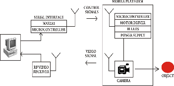
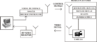
The proposed system comprises of two sections. The transmitter section consists of a computer , RS232
Interface, microcontroller, RF Transmitter, RF video receiver. The Receiver section consists of a Mobile Platform, RF receiver, microcontroller, RF camera, motor driver, IR LEDs. The computer at the transmitter section which receives the visual information from camera mounted on mobile platform works as control centre. Another function of control centre is to act as the web server that enables access to system from a remote location by using internet. The control centre is also responsible for transmitting the necessary control signal to the mobile platform.
The system can operate in four independent modes.
3.1 PC Controlled Mode
IJSER © 2011 http://www.ijser.org
International Journal of Scientific & Engineering Research Volume 2, Issue 4, April-2011 2
ISSN 2229-5518
In this mode the mobile platform is directly controlled
by control centre using a visual GUI program developed using Microsoft Visual Studio 6.0(Visual Basic programming language). The user can control the mobile platform after analyzing the received video.
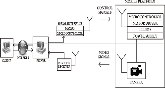
3.2 Internet Controlled Mode
This mode is an extension to the PC Controlled mode where client-server architecture is incorporated. This mode enables an authorized client computer to control the mobile platform from a remote location via internet. Client logs onto the control centre which provides all control tools for maneuvering the mobile platform. Instant images of the environment transmitted from the camera mounted on the mobile
In this mode the system is made to follow the object whose color information has been stored at the control centre in program developed in MATLAB. Basically the program performs the image processing of the object and generates the control signals in order to make the mobile platform to trace the object.
3.4 Motion Detection Mode
In this mode the platform is made to focus on a particular object whose security is our concern. The mobile platform transmits the visual information of the object to the control centre for analysis. A Program developed using MATLAB at the control centre is then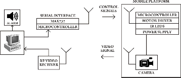
platform are used to generate appropriate control signals.
3.3 Tracing Mode
used to analyze four consecutive and based on this analysis a security alarm is raised if required.
4.1 Program for mode 1
IJSER © 2011 http://www.ijser.org
International Journal of Scientific & Engineering Research Volume 2, Issue 4, April-2011 3
ISSN 2229-5518
This program has been developed in Microsoft Visual Studio 6.0(Visual Basic programming language).It consists of 12 buttons, 2 checkboxes, 1 video box, 1 picture
box. These 16 buttons are configured as:
• 7 buttons to control the directions of the platform.
• 2 checkboxes for controlling lights and night
vision respectively.
• 2 buttons for camera control (start, stop).
• 2 buttons for capturing video.
• 1 button for capturing snapshot
The video box displays the video using VideoCapPro
ActiveX Control, received from the camera mounted on the mobile platform and similarly the picture box displays the snapshot taken when the button for capturing the snapshot is depressed. The program transmits the control signals via serial port using MSCOMM (Microsoft Common Control) component.
4.2 Program for mode 2
This program implements client-server architecture in VB using TCP and socket programming.
The client program (fig. 5) has total of 16 buttons,1 video box, 1 picture box and 2 text boxes which are configured as follows:
• 2 buttons for managing the connection between client and server.
• 1 text box to input the host IP address and other for communicating port.
• 7 buttons to control the directions of the mobile platform.
• 2 buttons for controlling lights and night vision respectively.
• 2 buttons for capturing video.
• 1 button for capturing snapshot.
• 2 buttons for camera control (start, stop).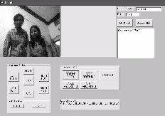
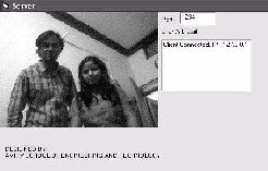
The server program (fig. 6) continuously listen to the port and establishes connection if requested. It then transmits the video to the client using VideocapX control and provides access to its serial port.
When connect button is depressed, client program connects to the server whose IP address has been specified in the IP text box at the given port using WINSOCK (Windows Socket) component. Once the connection is established, the server provides video feedback to the client. The client in turn controls the mobile platform via internet.
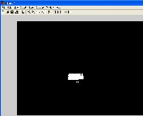
4.3 Program for mode 3
It has been developed in MATLAB (ver 7.01 from Math Works).The captured image is analyzed pixel by pixel. The screen is divided into four quadrants. Each pixel value is then compared with the stored color value. On comparing these values with the pixels of the captured image (fig. 7) of the object, those pixels are highlighted which matches with the specified color. The highlighted pixels (fig. 8) indicate the direction in which the mobile platform is to be moved. According to the quadrant of highlighted area, control signals are automatically transmitted to the mobile platform to track the object.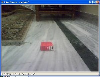
IJSER © 2011 http://www.ijser.org
International Journal of Scientific & Engineering Research Volume 2, Issue 4, April-2011 4
ISSN 2229-5518
difference between four consecutive frames, however, due to the unexpected traffic in the internet, delay in communication between the server and the end user may happen. This causes delays on executing commands and programs and transmitting on-site images.
Again, MATLAB is used for programming. The
GUI (fig. 9) has a button and one text box. The button incorporates multiple functions such as start camera, start and stop monitoring process. Monitoring can only be closed if correct password is entered in the text box. On activation the monitoring of scene in front of camera is performed continuously and visual information is sent to the control centre. At the control centre image processing is performed to detect any motion.
The designed advanced real time video motion detection system allows user to maneuver the mobile platform from a remote location. The system also provides feedback to the end user in terms of visuals rendering the system useful for spying purposes. This system integrates the functionality of four modes and selects one of them for unique application. The image processing discussed in mode 3 proves to be useful in industry applications and mode 4 can be useful for monitoring the highly restricted areas. Unlike most previous methods for real time video analysis the suggested approach used in mode 4 utilizes the
The first author Sumita Mishra is grateful to Prof. B. P. Singh, Maj. Gen. K.K. Ohri, Prof. S.T.H. Abidi and Brig. U. K. Chopra of Amity University, India for their support during the research work.
Nan Lu, Jihong Wang, Q.H. Wu and Li Yang IAENG International Journal of Computer Science, 35:1, IJCS_35_1_16
[3] "Real-Time Mobile Robot Teleoperation Via Internet Based On Predictive Control", Shihua Wang,Bugong Xu, Yunnhui LIU Yeming ZHOU, Front Mech. Engg. China, 3(3):299-306 2008.
[4] "Internet Control Of a Domestic Robot using a Wireless Lan", Johan Potgeiter, Glen Bright, Olaf Diegel, Sylvester Tlale Mechatronics and Robotic Research Group Institute of Technology and Engineering, Massey University, Auckland
[5] "Controlling Robot Through Internet Using Java", Mr. Ravindra Thamma, Dr. Luke H. Huang, Dr. Shi-Jer Lou and Dr. C. Ray Diez, Volume 20, Number 3 - June
2004 through August 2004 [6]http://gow.epsrc.ac.uk/ViewGrant.aspx?GrantRef
=EP/E027253/1 [7]http://www.mathworks.com/matlabcentral/f ileexchange/4412 [8]http://www.mathworks.com/matlabcentral/newsr eader/view_thread/243698
IJSER © 2011 http://www.ijser.org