International Journal of Scientific & Engineering Research Volume 2, Issue 4, April-2011 1
ISSN 2229-5518
A Novel Method for Fingerprint Core Point
Detection
Navrit Kaur Johal, Prof. Amit Kamra
Abstract- Fingerprint recognition is a method of biometric authentication that uses pattern recognition techniques based on high- resolution fingerprints images of the individual. Fingerprints have been used in forensic as well as commercial applications for identification as well as verification. Singular point detection is the most important task of fingerprint image classification operation. Two types of singular points called core and delta points are claimed to be enough to classify the fingerprints. The classification can act as an important indexing mechanism for large fingerprint databases which can reduce the query time and the computational complexity. Usually fingerprint images have noisy background and the local orientation field also changes very rapidly in the singular point area. It is difficult to locate the singular point precisely. There already exists many singular point detection algorithms, Most of them can efficiently detect the core point when the image quality is fine, but when the image quality is poor, the efficiency of the algorithm degrades rapidly. In the present work, a new method of detection and localization of core points in a fingerprint image is proposed.
Index Terms—Core Point, Delta Point, Smoothening, Orientation Field, Fingerprint Classes
—————————— • ——————————
Core points are the points where the innermost ridge loops
1. INTRODUCTION
ingerprints have been used as a method of identifying individuals due to the favorable characteristics such as “unchangeability” and “uniqueness” in an individual’s lifetime. In recent years, as the importance of information security is highly demanded, fingerprints are utilized for the applications related to user identification and authentication. Most Automatic Fingerprint Identification systems are based on local ridge features; ridge ending and ridge bifurcation, known as minutiae The first scientific study of the fingerprint was made by Galton who divided fingerprint into three major classes: arches, loops, and whorls. Henry, later refined Galton’s classification by increasing the number of classification. Henry’s classification is well-known and widely accepted. Henry’s classes consist of: arch, tent arch, left loop, right loop and
whorl .
At a global level the fingerprint pattern exhibits the area that ridge lines assume distinctive shapes. Such an area or region with unique pattern of curvature, bifurcation, termination is known as a singular region and is classified into core point and delta point. The singular points can be viewed as the points where the orientation field is
discontinuous.
————————————————
Navrit Kaur is pursuing M.Tech from Guru Nanak Dev Engineering
College Ludhiana E-mail: navrit.johal@gmail.com
Amit Kamra is with Guru Nanak Dev Engineering College, Ludhiana. E-
mail: amit_malout@yahoo.com.
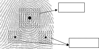
are at their steepest. Delta points are the points from which three patterns i.e. loop, delta and whorl deviate. Definitions may vary in deferent literatures, but this definition of singular point is the most popular one. Figure 1 below represents the core and delta points.
Core Point
Delta Points
Fig 1. The Core and Delta Points on a fingerprint image
This paper is organized as follows. In section 2, are discussed the different types of fingerprints. In Section 3 is explained the drawbacks with the existing techniques of core point detection. Section 4 focuses on the problem solution. In section 5, the core point is extracted using the proposed algorithm. The experimental results performed on a variety of fingerprint images are discussed in section 6 and the conclusion and future scope is discussed in Section
7.
IJSER © 2011 http://www.ijser.org
International Journal of Scientific & Engineering Research Volume 2, Issue 4, April-2011 2
ISSN 2229-5518
2 FINGERPRINT CLASSES
The positions of cores and deltas are claimed to be enough to classify the fingerprints into six categories, which include arch, tented arch, left-loop, right-loop, whorl, and twin-
loop.
Loops constitute between 60 and 70 per cent of the patterns encountered. In a loop pattern, one or more of the ridges enters on either side of the impression, recurves, touches or crosses the line of the glass running from the delta to the core, and terminates or tends to terminate on or in the direction of the side where the ridge or ridges entered. There is exactly one delta in a loop. Loops that have ridges that enter and leave from left side are called the Left Loops and loops that have ridges that enter and leave from right side are called the Right Loops. In twin loops the ridges containing the core points have their exits on different sides.
In a whorl, some of the ridges make a turn through at least one circuit. Any fingerprint pattern which contains 2 or more deltas will be a whorl pattern
In arch patterns, the ridges run from one side to the other of the pattern, making no backward turn. Arches come in two types, plain or tented. While the plain arch tends to flow rather easily through the pattern with no significant changes, the tented arch does make a significant change and does not have the same easy flow that the plain arch does.
In short, while classifying the fingerprints, we can make the assumption that if a pattern contains no delta then it is an arch, if it contains one (and only one) delta it will be a loop and if it contains 2 or more it will always be a whorl. If a pattern does contain more than 2 deltas it will always be an accidental whorl.
Fig 2. Classes of fingerprint (a)Arch, (b)Tented Arch, (c) Right Loop (d) Left Loop, (e) W horl and (f) Double Loop (The double loop type is sometimes counted as whorl)
Fingerprint friction ridge details are generally described in a hierarchical order at three levels, namely, Level 1 (pattern), Level 2 (minutiae points) and Level 3 (pores and ridge shape).Automated fingerprint identification systems (AFISs) employ only Level 1 and Level 2 features. No two fingerprints are alike, but the pattern of our fingerprint is inherited from close relatives and people in our immediate family. This is considered "level 1 detail." The detail of our actual finger and palm print is not inherited. This is considered "level 2 and 3 level detail" and is used to identify fingerprints from person to person.
The following figure briefly explains the three types of
levels of details in our fingerprint:
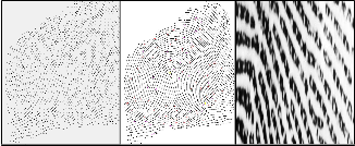
Fig 3. Level 1 , Level 2 and Level 3 Details
In this paper, we propose a new core point detection method which can precisely localize the core point and does not require further post processing as well. The proposed method only concentrates on the core point detection as most of the ridge characteristics e.g ridge endings and ridge bifurcations are present in the core block (centre).
3 PROBLEM FORMULATION
The existing techniques used for detection of core point do not produce good results for noisy images. Moreover, they
IJSER © 2011 http://www.ijser.org
International Journal of Scientific & Engineering Research Volume 2, Issue 4, April-2011 3
ISSN 2229-5518
may sometimes detect spurious core point due to the inability to work efficiently for noisy images. Also techniques like Poincare Index fail for Arch type of Image. The aim of proposed algorithm is to formulate a more accurate core point determination algorithm which can
a) Firstly, the image I(i,j) is divided into non overlapping blocks of size wXw.
b) The mean value M(I) is then calculated for each
block using the following equation:


w w
1 2 2
produce better localization of core points avoiding any
M (I ) =
2 I I I (i, j)
(1)
spurious points detected producing robust results for all
types of fingerprints that have been discussed in this paper.


w i = - w
2
j = - w 2
c) The mean value calculated above is then used to
find the variance using the following equation:


4 PROPOSED SOLUTION w w
2 2
V (I ) = 1
I I (I (i, j) - M (I ))2
(2)

Original Image


w i=-w
2 j =-w2
Normalized Image
d) If the variance is less than the global threshold value selected empirically, then the block is assigned to be a background region; otherwise, it is
assigned to be part of the foreground.
Smoothed Image
Fine Tuning of
Orientation Field
Core Point on the
Smoothed Image
Fig 4. The proposed methodology for Core Point Detection
4.1 SEGMENTATION
The first step of the fingerprint enhancement algorithm is image segmentation. Segmentation is the process of separating the foreground regions in the image from the background regions. The foreground regions correspond to the clear fingerprint area containing the ridges and valleys, which is the area of interest. The background corresponds to the regions outside the borders of the fingerprint area, which do not contain any valid fingerprint information. Cutting or cropping out the region that does not contain valid information minimizes the number of operations on fingerprint image. The background regions of a fingerprint image generally exhibit a very low grey-scale variance value, whereas the foreground regions have a very high variance. Hence, a method based on variance threshold can be used to perform the segmentation. The steps for mean
and variance based segmentation are as follows:
Fig 5. The result of segmentation using a variance threshold of 100 and a block size of 16 × 16.
4.2 NORMALIZATION
In image processing, normalization is a process that changes the range of pixel intensity values. Normalization is sometimes called contrast stretching. In more general fields of data processing, such as digital signal processing, it is referred to as dynamic range expansion. The purpose of dynamic range expansion in the various applications is usually to bring the image, or other type of signal, into a range that is more familiar or normal to the senses, hence the term normalization. Normalization is a linear process. If the intensity range of the image is 50 to 180 and the desired range is 0 to 255 the process entails subtracting 50 from each of pixel intensity, making the range 0 to 130. Then each pixel intensity is multiplied by 255/130, making the range 0 to 255.
Let I(i,j) denote the gray-level value at pixel (i,j), M0 and V0 denote the estimated mean and variance of I, respectively, and N(i,j) denote the normalized gray-level value at pixel (i, j). The normalized image is defined as follows:
IJSER © 2011 http://www.ijser.org
International Journal of Scientific & Engineering Research Volume 2, Issue 4, April-2011 4
ISSN 2229-5518
M +
V (I (i, j) - M )2
if I (i, j) M
Ridge smoothing is then performed which is a process of

N (i, j) = i 0 0 i
(3)
finding out the valid frequency of the binary image of
LM 0 -
V0 ( I (i, j) - M i )
otherwise
ridges. Filters corresponding to these distinct frequencies
Normalization is a pixel-wise operation. It does not change the clarity of the ridge and valley structures. The main purpose of normalization is to reduce the variations in gray- level values along ridges and valleys, which facilitates the subsequent processing steps.
Fig 6. Result of normalization.(a) Input image(b) Normalized (M0 = 100, VAR0 = 100).
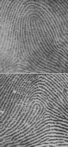
and orientations are then generated. Fig 7 indicates the results obtained after smoothing the image.
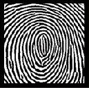
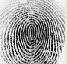
Fig 7. Original and Smoothed Fingerprint images respectively.
The direction of gravity of progressive blocks is then determined, using the following equations (P=3):
4.3 ORIENTATION ESTIMATION
P -1 P -1
A = I IVx
k = 0 l = 0
and
P -1
B = I
k = 0
P -1
IV y
l = 0
(7)
The orientation flow is then estimated using the least square method using the following equations after dividing the input image I into non overlapping blocks of size wXw and
As we know that singular points are the points where the orientation field is discontinuous, hence orientation plays a crucial role in estimating the core point on a fingerprint
then computing the gradients a x
and a y at each pixel.
image. Hence, we need another mechanism to fine tune the
Vx(i, j) =
i + w / 2
I
j + w / 2
I
2ax(u, v)ay(u, v)
(4)
orientation field so as to avoid any spurious core points and the irregularities that has occurred because of noise. The
u =i -w / 2 v = j -w / 2
orientation field for coarse core point is then fine tuned by
adjusting orientation using the following :
Vy(i, j) =
i+ w / 2
I
j + w / 2
I
a2 x(u, v)a2 y(u, v)
(5)
If : B( i , j ) -: 0 then: 8 = 0.5 tan-1( B / A)
(8)
u =i-w / 2v= j -w / 2
else:
8 = n / 2
Where
a x (u,v) and
a y (u,v) represents gradient
if 8 0
then
magnitudes at each pixel in x and y directions respectively.
if : A 0
then: 8 = 8 + n / 2
else: 8 = 8 + n
The direction of block centered at pixel (i,j) is then
computed using the following equation:
else if
A 0
then: 8 = n / 2
8 ( i ,
j ) =
1 tan

- 1 V y ( i ,
j ) \
1
(6)
Hence we calculate the value 8, which is the orientation value of the image.
2 V x ( i. j )
Due to the presence of noise, corrupted ridge and valley structures, minutiae etc. in the input image, the estimated local ridge orientation, e (i,j), may not always be correct. A low-pass filter is hence used to modify the incorrect local ridge orientation.
4.4 SMOOTHING AND FINETUNING
4 PROPOSED ALGORITHM
1. The original fingerprint image is first segmented and normalized using equations (1), (2) and (3).
2. Determine the x and y magnitudes of the gradients
Gx and Gy at each pixel.
IJSER © 2011 http://www.ijser.org
International Journal of Scientific & Engineering Research Volume 2, Issue 4, April-2011 5
ISSN 2229-5518


3. Divide the input image into blocks of size wXw.
4. Estimate the local orientation using equations
(4),(5),(6) and perform ridge smoothening.
5. Of the wXw image size, determine the direction of gravity of progressive blocks (non-overlapping sub block ) using equation (7).
6. Fine tune the orientation field.
7. The blocks with slope values ranging to 0 to pi/2 are located. Then a path is traced down until we encounter a slope that is not ranging from 0 to pi/2
and that block is marked.
8. The block that has the highest number of marks will compute the slope in negative y direction and output on x and y position which will be the core point.
5 RESULTS AND DISCUSSION
The proposed technique can localize the fingerprints at a good success. Experiments have been performed on nearly
180 fingerprints from different fingers and a variation in
noise has been taken into consideration. The results have been obtained in MATLAB, the core point positions hence obtained are used to narrow down the search when using a huge database of fingerprint images in applications like biometrics security, forensics etc. The following table clearly compares the accuracy of results of the proposed technique with the existing state of the art technique.


TABLE 1: Comparison of results of the proposed technique with the existing technique.
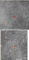
The proposed algorithm gives us near accurate results for noisy images as shown below:
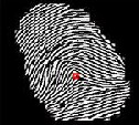
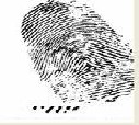
Fig 10. Accuracy of the proposed technique for a poor input image.
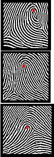
But the algorithm failed its core point detection for images having a very poor quality as shown in figure 11. Those fingerprints are too oily or wrinkled.

Fig 11. Poor quality fingerprint images
6 CONCLUSION AND FUTURE SCOPE
This paper proposes a novel method to consistently and precisely locate the singular points in fingerprint images.
The method applied is based on the enhanced fingerprint
IJSER © 2011 http://www.ijser.org
International Journal of Scientific & Engineering Research Volume 2, Issue 4, April-2011 6
ISSN 2229-5518
image orientation reliability. Our future work will focus on improvements in locating the secondary singular points of fingerprint images and classifying the fingerprints based upon the location of the singularities so that the computational time for matching fingerprints in a huge database may reduce.
7 REFERENCES
[1] Keokanlaya Sihalath, Somsak Choomchuay, and Kazuhiko Hamamoto, “Core Point Identification with Local Enhancement”, JCSSE, May 13-15, 2009 (Vol. 1)
[2] Mohammed S. Khalil, Dzulkifli Muhammad, Muhammad K. Khan and Khaled Alghathbar, “Singular Point Detection using Fingerprint Orientation Field Reliability” , International Journal of Physical Sciences Vol. 5(4), pp. 352-
357, April 2010
[3] Wang Feng, Chen Yun , Wang Hao, Wang Xiu-you “Fingerprint
Classification Based on Improved Singular Points Detection and Central Symmetrical Axis” , 2009 International Conference on Artificial Intelligence and Computational Intelligence
[4] Filipe Magalhães, Hélder P. Oliveira, Aurélio C. Campilho, “A New
Method for the Detection of Singular Points in Fingerprint Images” , 978-1-
4244-5498-3/09©2009 IEEE
[5] Galton F., Fingerprint, McMillan, London, 1892.
[6] Henry E., “Classification and uses of fingerprints” , Rout ledge, London,
1900.
[7] Weiwei Zhang, Yangsheng Wang , “Core-Based Structure Matching Algorithm of Fingerprint Verification” , National Laboratory of Pattern Recognition, Institute of Automation,Chinese Academy of Sciences
[8] Tomohiko Ohtsuka, Daisuke Watanabe, Hiroyuki Aoki1, “Fingerprint Core And Delta Detection By Candidate Analysis” , MVA2007 IAPR Conference on Machine Vision Applications, May 16-18, 2007, Tokyo, Japan
[9] S.Chikkerur, C. Wu and Govindaraju, “A Systematic Approach for
Feature Extraction in Fingerprint Images”, ICBA 2004.
[10] L. Hong, Y. Wan, and A. Jain, “Fingerprint Enhancements: Algorithm and Evaluation” , Proc. IEEE Trans. on Pattern Analysis and Machine Intelligence, vol.20, no. 8, pp. 777-789, 1998.
[11] M. Liu, X. Jiang, and A. C. Kot, “Fingerprint Reference Point Detection” ,
Journal of Applied Signal Processing, vol. 4, pp. 498–509, 2005.
[12] C.-Y. Huang, L. Liu, and D. D. Hung, “Fingerprint Analysis and Singular
Point Detection”.
[13]Ramandeep Kaur, Parvinder S. Sandhu, Amit Kamra,”A Novel Method for Fingerprint Feature Extraction” 2010 International Conference on
Networking and Information Technology 978-1-4244-7578-0 © 2010 IEEE .
[14] Bob Hastings, “A Statistical Investigation of Fingerprint Patterns
Department of Computer Science & Software Engineering The University of
Western Australia, Australia.
Navrit Kaur Johal received her B.Tech degree in Computer Science and Engineering from AIET, Faridkot and is pursuing her M.Tech in Computer Sc. and Engg from Guru Nanak Dev Engg. College, Ludhiana.
Amit Kamra received his B.Tech degree in Electronics Engineering in
2001. and completed his M.Tech in Information Technology in 2004.
He is working as Associate Professor in Guru Nanak Dev Engg. College, Ludhiana and is currently pursuing his Ph.D in image processing.
IJSER © 2011 http://www.ijser.org