International Journal of Scientific & Engineering Research, Volume 4, Issue 6, June-2013 93
ISSN 2229-5518
AUTOMATIC SOLAR TRACKER SYSTEM.
Nikesh.D.Watane Rakesh.A.Dafde watanenikesh@gmail.com rakeshdafde7@gmail.com
ABSTRACT: This paper presents the hardware design and implementation of a system that ensures a perpendicular profile of the solar panel with the sun in order to extract maximum energy falling on it renewable energy is rapidly gaining importance as an energy resource as fossil fuel prices fluctuate. The unique feature of the proposed system is that instead of taking the earth as its reference, it takes the sun as a guiding source. Its active sensor constantly monitors the sunlight and rotates the panel towards the direction where the intensity of sunlight is maximum. The light dependent resistor’s do the job of sensing the change in the position of the sun which is dealt by the respective change in the solar panel’s position by switching on and off the geared motor the control circuit does the job of fetching the input from the sensor and gives command to the motor to run in order to tackle the change in the position of the sun. With the implementation the proposed system the additional energy generated is around 25% to 30% with very less consumption by the system itself. In this paper, an improvement in the hardware design of the existing solar energy collector system has been implemented in order to provide higher efficiency at lower cost.
Keywords-Four quadrant sensor, Light Dependent Resistor (LDR), Automatic Solar Tracking System (ASTS).
1 INTRODUCTION
In remote areas the sun is a cheap source of electricity because instead of hydraulic generators it uses solar cells to produce electricity. While the output of solar cells depends on the intensity of sunlight and the angle of incidence. It means to get maximum efficiency; the solar panels1 must remain in front of sun during the whole day. But due to rotation of earth those panels can’t maintain their position always in front of sun. This problem results in decrease of their efficiency. Thus to get a constant output, an automated system is required which should be capable to constantly rotate the solar panel. The Automatic Solar Tracking System (ASTS) was made as a prototype to solve the problem, mentioned above. It is completely automatic and keeps the panel in front of sun until that is visible. The unique feature of this system is that instead of take the earth as in its reference, it takes the sun as a guiding source. Its active sensors constantly monitor the sunlight and rotate the panel towards the direction where the intensity of sunlight is maximum. In case the sun gets invisible e.g. in cloudy weather, then without tracking the sun the ASTS keeps rotating the solar panel in opposite direction to the rotation of earth. But its speed of rotation is same as that of earth’s rotation2. Due to this property when after some
time e.g. half an hour when the sun again gets visible,
the solar panel is exactly in front of sun. Moreover the system can manage the errors and also provides the error messages on the LCD display. In manual mode, through the software (GUI) at computer, the solar panel can be rotated at any desired angle.
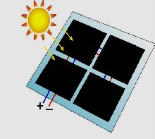
Fig1: Solar panel
Heliostat and Parabolic Trough. ASTS can be used for Parabolic Trough tracker, Dishes tracker, PV (Photovoltaic generator) tracker, Heliostat, Solar Furnace and so on. Even though the theory of the controller system is similar to all the applications, there are some differences: the precision requirement for dishes tracker is stricter than PV tracker, while the
Heliostat and solar furnace need the strictest precision
IJSER © 2013 http://www.ijser.org
International Journal of Scientific & Engineering Research, Volume 4, Issue 6, June-2013 94
ISSN 2229-5518
requirement, and more difficult to apply solar sensor to make a closed-loop control system. So, when design these systems, selection of motor type, controller type and tracking mode should be different.
2 STRUCTURE OF ASTS
ASTS is a hybrid hardware/software project. Its general structural diagram is shown in figure-3.
2.1. The software includes:
• VB 6.0 based GUI.
• Microsoft Access Database.
• Embedded Software (written in C) for microcontroller AT89c52.
2.2. The hardware includes:
• Solar panel assembly structure containing six functional sensors, stepper motor and solar cells.
• System Control Unit containing LCD, Keypad, Error
Indicators and Emergency Stop switch.
• Complete PCB containing two microcontrollers (89c52). First one is the “Master Microcontroller” which controls the automatic operation of ASTS.
While second one, the “Slave Microcontroller” serially communicates (RS232) with VB software in
computer.
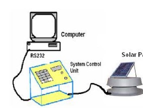
Figure2: General Assembly of ASTS
3 MOTOR SELECTION
There are many types of motor can be selected in ASTS design. Currently, several types of motors being used in the area of ASTS around the world are Step- motor, Servo-motor, AC asynchronous motor, permanent magnetic DC servo motor, permanent magnetic brushless synchronous motor, etc. Generally speaking, as the gear ratio is high for the transmission system, motor control precision has very small impact to the tracking precision. For example, for a system with the gear ratio of 20000:1, the tracker only covers an angle of 0.314mrad when a one complete circle is finished by the motor. Therefore, all kinds of the motor can satisfy the precision of the tracking system. However the feature of each type of motor is different.
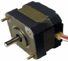
Fig. 3: stepper motor
First of all, let’s take a look at the AC asynchronous motor. To use this kind of motor, we need an encoder to locate the position of the tracker. In our project, we install an encoder at the end of AC motor. The PLC accepts the pulse to locate the tracker, while the transducer is used to adjust the tracker’s speed. Certainly, we can install an encoder at the end of the transmission to ensure the position of the tracker. The obvious advantage to use AC asynchronous motor is its price. Even though it can achieve all the needed functions, AC asynchronous motor is too heavy, too large, and too low in efficiency
IJSER © 2013 http://www.ijser.org
International Journal of Scientific & Engineering Research, Volume 4, Issue 6, June-2013 95
ISSN 2229-5518
to be installed. Also, for this type of motor, the torque at low speed is very small. In addition to these disadvantages, it needs the work frequency be above
5Hz to function properly. The lowest work frequency in our project is 10Hz. As such, the possibility for us to use AC asynchronous motor in the future is eliminated. Secondly, let’s compare the features of DC Servo-Motor and AC servo-motor. There are two types of DC servo-motor: motor with brush and motor without brush. Motor with brush is low in cost, simple in structure, and high in start torque. Also it has wide range of speed adjustment, is easy to control. Though it needs maintenance from time to time, it is very convenient to repair (replace the brush). However it produces electro-magnetic interfere. Motor without brush is small in size, light in weight, high in output, fast in response, small in inertia, smooth in spinning, stable in output torque, low motor maintenance fee, high in efficiency, low in electro-magnetic radiation, long life, and can be applied in different working environments. However it has more complex control system. AC servo-motor is also type of motor without brush. There are two types of AC servo-motor: synchronous AC motor and asynchronous AC motor. Currently, synchronous AC motor is generally used in movement control. It can cover a wide power range, which could be up to a very high power level. Nowadays, with the fast development of semiconductor technology, the shift frequency of power assembly, and the processing speed of micro- computer have been increased significantly. As such, it is possible to put the AC motor controller into a two- axial coordinate system to control the directional current components, in order to achieve the performance similar to the DC motor.
Fourthly, the comparison between AC servo- motor and step motor is done. AC servo-motor runs smoothly during low speed period; while step-motor is apt to have low-frequency vibration. In terms of the frequency-torque Characteristics, the output torque of step-motor decreases with the increasing of rotation speed. Furthermore the decrease is steep in high-speed range. AC servo-motor has a comparably stable output torque, when the rotation speed is within the rated
rotation speed. It gives the constant output power when the rotation speed is beyond the rated value. Step-motor doesn’t have the overload capability; while AC servo-motor posses a satisfactory overload capability. The Panasonic AC servo-system is an example: The maximum Output torque is three times big of the rated output torque, which can be used to overcome the inertia load during the start period. As the step-motor doesn’t have the overload capability, a much bigger size of step-motor is needed. Obviously the step-motor will be over-sized during normal operation. Controller’s type of Step-motor is open- loop type. It is easy to have the error of “step loss” or blockage when the start frequency is high or the load is heavy. Also it is easy to have the error of overshoot when it is stopped. So, to make sure the precision of control be achieved, designer needs to pay more attention to the speed-increase or speed-decrease periods. AC servo-motor system is a closed-loop system. It is possible for the driver-component to sample the signal from the motor encoder to complete a “position cycle” and “speed cycle” internally. As such, AC servo-motor system generally will not have the errors of “step loss” or “overshooting”, and is more reliable in terms of controlling performance. Step- motor needs 200 to 400 mil-seconds to accelerate from still to a typical working speed of several hundred rpm. AC servo-motor is better in terms of acceleration performance. For example, Panasonic MSMA 400W needs only a few mil-seconds to accelerate from still to its rated speed of 3000RPM. So it is clear that step- motor’s performance is not so good. However it’s cheaper. Started from late 70s and early 80s, with the development of micro-process technology, high- power, high-performance semiconductor technology, and manufacturing technology of permanent magnetic material, the performance price ratio of AC servo- system has been improved significantly. Price of AC servo-system also is gradually deceasing in recent years. AC servo motor is becoming the dominant product. The conclusion is that all the motors, step- motor, AC asynchronous motor, DC motor with/without brush, AC servo-motor, can be applied in ASTS. Asynchronous AC motor is the cheapest. But it
is big in size, and low in technical specification. The
IJSER © 2013 http://www.ijser.org
International Journal of Scientific & Engineering Research, Volume 4, Issue 6, June-2013 96
ISSN 2229-5518
step-motor has a simple controlling mode and is also low in price. AC servo-motor has the best performance and wide power range. Its price is also the highest. As for the performance and price for permanent magnetic DC brushless motor, they are both rated between step- motor and AC servo-motor. Its performance is close to servomotor. For the situations that the output torque is not very high (less than 2 NM), permanent magnetic DC brushless motor is a good option.
Fig 4: Four quadrants Sensor In four quadrant sensor system
4 SOLAR SENSOR
Dish type tracking controller and PV tracking controller can be both applied as four- quadrants solar sensor to correct tracking bias. It is known that solar sensor will lose its functionality temporally when it’s cloudy. In the area of solar thermal generation, solar sensor system usually follows the equation based on the astronomic formula to locate the position of the sun. When a MPU (micro- processor unit) is applied to calculate the sun’s position, because of its low process speed and low precision, it’s necessary to include a solar sensor to make a closed loop system. If the tracking system uses a PC or a high-performance DSP as the controller, the bias for the calculated sun position will be within one percent of mrad (milliradian), when the system clock is precisely set (Direct time from GPS is an option). No solar sensor is needed to track the sun, especially when the slope error and the gear-diastema are all small. Exception happens when the motor is a step- motor and the output torque is not enough. The situation can lead to a blockage of the motor (For example, a windy weather), which will fail the tracking system to track the sun precisely. As such, a closed loop solar sensor is recommended in such system. There are many kinds of solar sensor. The four- quadrants sensor was used in our project as
shown in
In four quadrant sensor system, the Photovoltaic current will be bigger for the quadrant of bigger solar facular area, which will indicate whether the sun’s incident ray is parallel with the axial direction of the sensor, then to adjust the angle by the motor. It should be stressed during the solar sensor design that the inside wall of the solar sensor needs to be blacken to avoid misjudgment by the reflection of sunray inside the solar sensor
5 WORKING OF ASTS Basic Principle:
The basic functional blocks of this system are four sensors1, and their operation depends upon the intensity of light falling on solar panel. All sensors (each with different functionality) send their output to microcontroller AT89c52. Then the microcontroller executes predefined task in its software. These sensors are being used with following names and functionality.
Sun Tracking Sensors (STS) These two sensors are mounted in “V” shape (figure-6) exactly in the middle of the solar panel (figure-8). The automatic sun tracking is. Accomplishedaccordingtofollowing3
IJSER © 2013 http://www.ijser.org
International Journal of Scientific & Engineering Research, Volume 4, Issue 6, June-2013 97
ISSN 2229-5518
stepdiagram
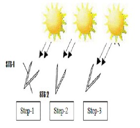
Figure5: Basic Automatic Sun Tracking Operation
• Step-1 shows that when the sun is in front of solar panel, both sensors i.e. STS-1 and STS-2 are getting same amount of light.
• In step-2, after some time as the earth rotates the solar panel gets repositioned with respect to sun and STS-1 obtains less amount of light. At this point the LDR i.e. STS-1 sends signal to the microcontroller (figure 3). Then the controller1 rotates motor, resulting the rotation of solar panel towards the sun.
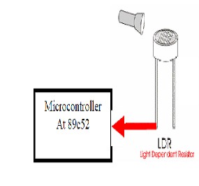
Figure6:Interface of LDR with Microcontroller
Night Time Fault Detector (NTFD) in routine work of the system if a general fault2 occurs during nighttime then the next morning it would not work. So at the next sunrise, this sensor detects whether the solar panel is ready for tracking or not. As shown in figure-8, the NTFD is mounted in east of the solar panel so in normal conditions it does not work because it gets lesser intense light (predefined) as compared to the middle sensors i.e. STS-1 and STS-2, but as the fault arises, it starts working. Day Time Fault Detector (DTFD) except some special conditions e.g. cloudy weather etc, the ASTS is supposed to track the sun the whole day. If the panel stops rotation then DTFD detects this type of fault. The mounting strategy of this sensor is same as that of NTFD except that it is mounted in the west. Night and Cloud Detection In a cloudy day light intensity is less than a normal day.

Figure7: Sensor mounting assembly on solar panel
6 CONTROL STRATEGY OF ASTS
For a successful operation, the ASTS has two types of control approach.
IJSER © 2013 http://www.ijser.org
International Journal of Scientific & Engineering Research, Volume 4, Issue 6, June-2013 98
ISSN 2229-5518
• Automatic Control
• Manual Control
6.1. Automatic Control
With the help of an efficient algorithm (written in C) only one Master Microcontroller1 is being used to manage the automatic operation of ASTS. This controller has following functions.
• Senses all of six sensors.
• Drives stepper motor.
• Drives LCD.
• Controls the warning indicators e.g. buzzer, LED’s etc.
• Communicates (by parallel port) with the slave microcontroller. The central driving components of automatic control are only six sensors. Their operation has been explained on the previous page.
6.2. Manual Control
As no human made system is so perfect so an unpredictable fault may occur in the any system. That is why a manual control option was also kept in ASTS. While designing this part of control two objectives were kept in mind:
• The manual control should work efficiently.
• It should be as user friendly as possible. Following two approaches have been used to accomplish the manual control.
• Stand Alone System Control Unit
• Computer based control unit
6.3. Stand Alone System Control Unit
It is a simple user interface, which includes onboard LCD, Keypad, Buzzer and a complete PCB of the system circuit. The LCD (Hitachi HD44780) displays different messages, which can help the user in manually operating the system. While the keypad includes keys of Numeric Digits, Emergency Stop, clock wise rotation and counter clockwise rotation. Using keypad a user can manually rotate the solar panel by entering angle from 0o to 180o. The angle value is limited to only 180 values because after sunrise, the earth almost rotates only 180 degrees and then the sun disappears. The advantage of this unit is that to run the system it does not need computer but its disadvantage is that at a time it controls only one solar panel. In figure-3 this unit shown in yellow color, in middle of solar panel and computer terminal.

Figure 8: Flow Chart showing automatic operation of ASTS
IJSER © 2013 http://www.ijser.org
International Journal of Scientific & Engineering Research, Volume 4, Issue 6, June-2013 99
ISSN 2229-5518
7 ADVANTAGES& DISADVANTAGES
6.4. Computer Based Control Unit
This is completely software based control, written in VB 6.0. It incorporates a GUI (figure-10) and a Database, linked with Microsoft Access. Using this software the computer serially communicates (RS232) with the ASTS. The Slave microcontroller (89c51) of the system makes this communication successful. Due to some fault if the solar panel stops rotating, then with the help of this software a user can:
• rotate the solar panel manually.
• stop all operations of ASTS (in emergency case)
The database of this system can be used to keep records, which can be retrieved even after a long time. While saving the new data, the database automatically takes the date and time from the computer and keeps them saved along with the data, entered by the human being. The advantages of computer-based control include:
• Facility of Database.
• At a time this software can handle three ASTS
systems.
• It has an attracting GUI
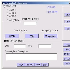
Figure9. VB based GUI of ASTS
7.1 ADVANTAGES:
• This automatic solar tracker is easy to implement since its construction is simple.
• With the implementation the proposed system the additional energy generated is around 25% to 30% with very less consumption by the system itself.
• The solar panel with the sun in order to extract maximum energy falling on it renewable energy is rapidly gaining importance as an energy resource as fossil fuel prices fluctuate.
7.2 DISADVANTAGES:
• This system cannot be used in rainy season.
• Initial cost is high.
8 APPLICATIONS
• This system software and hardware can be used to drive a real and very huge solar panel.
• The computer and System Control Unit would have a wireless communication with the mechanical structure of solar panel.
• To make emergency control better more powerful microcontrollers e.g. PIC 16F877A would be used.
9 CONCLUSION
The designed that system which ensures 25 to 30% of more energy conversion than the existing static solar module system. Although ASTS is a prototype towards a real system, but still its software and hardware can be used to drive a real and very huge solar panel. A small portable battery can drive its control circuitry. Therefore by just replacing the
IJSER © 2013 http://www.ijser.org
International Journal of Scientific & Engineering Research, Volume 4, Issue 6, June-2013 100
ISSN 2229-5518
sensing instrument, its algorithm and control system can be used in RADAR and moveable dish antennas.
References
[1] A.K. Saxena and V. Dutta, “A versatile microprocessor based controller for solar tracking,” in Proc. IEEE, 1990, pp. 1105 – 1109.
[2] Muhammad Faheem Khan and Rana Liaqat Ali
“Automatic Sun Tracking System (ASTS)”, Faculty of
Electronics Engineering, Air University.
[3] T, Esram and P.L. Chapman, “Comparison of Photovoltaic Array Maximum Power Point Tracking Techniques,” IEEE Transactions
[4] Chong, K.K.; Wong, C.W. General formula for one-axis sun tracking system and its application in
improving tracking accuracy of solar collector “Solar
Energy. 2009, 83, pp.298-305.
[5] Al-Mohamad, A.” Efficiency improvements of photo-voltaic panels using a sun tracking system”. Applied Energy 2004, 79, pp.345-354.
[6] Roth, P., Georgieg, A., Boudinov, H. “Design and construction of a system for sun-tracking”, Renewable Energy. 2004, 29, pp.393- 402.
[7] Saxena,A.K.; Dutta, V.“A versatile microprocessor based controller for solar tracking,” Photovoltaic Specialists Conference, 1990. Conference Record of the Twenty First IEEE, 21-25 May 1990, Page(s):1105
-1109 vol.2
[8] Pritchard, D., “Sun tracking by peak power positioning for photovoltaic concentrator arrays,” IEEE Control Systems Magazine, Volume 3, Issue 3, August 1983, pp. 2 – 8
[9]Reddi Chandra sekhar,”Automatic sun tracking system”.
IJSER © 2013 http://www.ijser.org