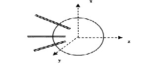
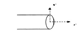
The co-ordinate system of the lens in which the primary feeds are embedded is shown in Figure1a [9]. Figure1b is the coordinate system native to a primary feed.
Figure 1a A Lens with three feeds
International Journal of Scientific & Engineering Research, Volume 2, Issue 11, November-2011 1
ISSN 2229-5518
Analysis of a Lens Based Antenna Using
Spherical Modes
Prakash Biswagar, Dr. S.Ravishankar, S.Shashidhar
Abstract - A fixed shaped beam antenna offers an excellent compromise between cost and system performance in high data rate systems operating in the frequency range of 5- 65 GHz. Shaped Dielectric Lenses perform the task of collimation and shaping, along with physically small feed antennas, to obtain multiple and shaped beams in a fixed set of directions. Lenses are inherently broadband, easy to fabricate, have lower dimensional tolerances, cost effective and act as radome for the primary radiators that are embedded inside or placed behind the lens. Earlier techniques for the analysis of shaped dielectric lenses, employed ray tracing methods of GO and PO, that are valid only in the far field of a primary point source type of radiator. But the dielectric lens is in the near field of finite sized primary radiators oriented at different angles and at different distances from the lens center. In this paper we discuss, a new accurate analytical procedure for the radiation pattern of a spherical lens excited by a rectangular patch. The lens is treated as a scatterer. Techniques for radial translation and spatial rotation of the small aperture Spherical Modal Complex Coefficients (SMCC) are utilized to align them to the phase center of the Dielectric Lens. The SMCC of the scattered fields due to the lens are then obtained by application of boundary conditions. Sample computations are performed to demonstrate the approach and supported by experimental results.
Index Terms - MBS, Smart Antenna, Dielectric Lens, SME, SVWF, SMCC
—————————— ——————————
Modal Expansion (SME) approach. Earlier SME approaches
ew frequency bands were opened up in 5 to 11 GHz, to support WLAN applications and in 40 to 65 GHz bands to support Mobile Broadband Systems
(MBS).To achieve a high rate goal, ‗Smart Antennas‘ were proposed at the base stations[1]. An adaptive multi beam smart antenna has the ability to cope with a rapidly changing environment by distributing the limited power of solid state amplifiers in the best possible way within the cell, as to ensure sufficient signal to noise ratio at a receiver to sustain the desired high data rates. However a cost effective implementation of a ‗Smart Antenna‘ is limited due to high cost of RF array elements, RF distribution and phasing [1-2].
It is for this reason that fixed shaped beam antennas
offer an excellent compromise between cost and system performance especially in an urban scenario where dense
traffic occurs in specified directions only.
Shaped Dielectric Lenses perform the task of
collimation and shaping, along with physically small feed
antennas, to obtain multiple and shaped beams in a fixed
set of directions. Lenses are inherently broadband, easy to fabricate, have lower dimensional tolerances, cost effective
and provide a covering radome for the primary radiators that are embedded inside or placed behind the lens. The drawback thus far has primarily been an accurate analysis, apart from reducing internal reflections, dielectric losses and eventually the size of the dielectric lens [2-4].
Earlier techniques for the analysis of shaped dielectric
lenses, employed ray tracing methods of GO and PO, that
are valid only in the far field of a primary point source type
of radiator. But in reality, the dielectric lens is in the near
field of finite sized primary radiators oriented at different
angles and at different distances from the lens center.
In this work, a new accurate analytical procedure is
proposed for the radiation pattern of multiple primary
radiators in the near field of a dielectric lens using Spherical
to solve for the field scattered by a dielectric sphere approximated the primary radiator as a far field Huygens source [9].
The lens is treated as a scatterer. Techniques for radial translation and spatial rotation of the small aperture Spherical Modal Complex Coefficients (SMCC) are utilized to align them to the phase center of the Dielectric Lens. The SMCC of the scattered fields due to the lens are then obtained by application of boundary conditions.
The analysis is flexible enough to accommodate different types of radiators and different shapes for the dielectric lens.
Consider a set of primary feeds radiating in the presence of a dielectric sphere as shown below.
The co-ordinate system of the lens in which the primary feeds are embedded is shown in Figure1a [9]. Figure1b is the coordinate system native to a primary feed.
Figure 1a A Lens with three feeds
IJSER © 2011
International Journal of Scientific & Engineering Research, Volume 2, Issue 11, November-2011 2
ISSN 2229-5518
Ei (R
, '' , '' )
(A tn M'' n
Btn N '' )
(3)
H (R, " , " ) ( jY ) A N"
B M" )
i 0 tn mn n
tn mn
(4)
Figure 1b A single primary feed
The near fields radiated by the primary feed at any point in its own coordinate system are given by
In equation(3) & (4) the symbol ‖ is used to represent a radiator coordinate system that has been translated to the lens phase center but not spatially aligned to it. The translated SMCC‘s Atn and Btn are computed for a distance
‗d‘ between the primary radiator aperture centre and the
lens phase centre (Figure 1a) using the expressions below.
A tn (a n A vn b n B vn )
v (5)
' ' '
' '
B (a B
b A )
Ei (R , , )
(a n Mmn n
bn Nmn)
(1)
tn n vn v
n vn
(6)
' ' '
' '
The running index ‗v‘ is up to N
. The translation
Hi (R , , )
'
( jYO )
n
'
(an Nmn
bnMmn)
(2)
max
coefficients Avn and Bvn in (5) and (6) are given by [6].
p
Here M mn and N mn are the mutually orthogonal TE & TM Spherical Vector Wave Functions (SVWF) respectively,
e jt
Avn C(v, n)[( j) {n(n 1) v(v 1) * a(m, n,m,v, p)}Z p (kd)]
p
(7)
defined in [10] with a
time variation. The TE and TM p
Spherical Modal Complex Coefficients (SMCC) are denoted
Bvn C(v, n)[( j)
p
{2jmkd * a(m, n,m, v, p)}Zp (kd)]
by a n and bn
respectively. Here ‗n‘ is the spherical modal
e j m
Where
(8)
index and ‗m‘ is the azimuthal index occurring as
. For
linearly polarized primary radiators m 1 . Yo is the
admittance of the surrounding medium. The maximum
value of the running index ‗n‘ is set to
C(v, n) (1) 2mv ( j) vn
(2v 1)
![]()
2v(v 1)
and
N max ceil[k * lensdia] that accounts for more than 99.9%
Zp (kd) h 2 (kd)
is the spherical Hankel function of second
of the energy radiated by collimating type of antennas as shown by Arthur [12] and like the ones considered in this
kind.
The summation over ‗p‘ runs as![]()
![]()
n v .............n v
and
work.
Compute the far fields over an enclosing sphere centered
at the aperture center by aperture field integration described in [11].The fields over an enclosing sphere may also be obtained by an accurate measurement for any one primary radiator in an anechoic chamber. Using the
includes 1+max [v, n] terms. The values of a p a(m, n,m, v, p) are computed using the recursion relations [6] as below.
p3p4 (p2 p1 4m2 )p2 pap 0
(9)
orthogonality of the SVWF‘s, the SMCC‘s
a n and b n of the
Where
primary radiator are obtained. These are valid anywhere in
a p a(m, n,m, v, p)
,
p n v, n v 2,........(,n v) and
near and far space [9].
p
[(n v 1)2 p2 ][p2 (n v)2 ]
![]()
4p2 1
(10)
The SMCC of the primary radiator are to be translated to
the phase center of the dielectric sphere, as it is the
reference point for evaluating the fields finally scattered by the lens. This is accomplished by translation addition theorems and a recursion method of computation described in [6-7].But it should be noted that while the translated origin would coincide with the phase center and coordinate origin of the dielectric lens, it is not yet spatially aligned to it. The translated SMCC would have the following
The recursion relation is performed in the descending order of the index.
The translated SMCC in equations (5) and (6) are now referred to the lens phase centre coordinate system by performing a spatial rotation. If R represents the mathematical rotation group, then as described by
n
expressions.
Edmonds [8], the symbol
IJSER © 2011
Dmu(R) would be the matrix of
International Journal of Scientific & Engineering Research, Volume 2, Issue 11, November-2011 3
ISSN 2229-5518
rotation coefficients for one element of the rotation group
defined by a set of three Eulerian angles
(, , ) that
Ei Es E d
(15)
would align the translated primary radiator coordinate
system with the lens phase centre coordinate system. The translated and rotated SMCC of the primary radiator are
Hi Hs Hd
(16)
computed using
Atn
and
B tn in (5) and (6) after
substituting into the expressions below.
Hi Hs Hd
(17)
A nm
A tn u
n (R)
(11)
Bnm
B tn u
n (R)
(12)
In the case of a spherical dielectric lens of radius ro, the
orthogonality conditions of SVWF [10] can be invoked on the surface of the sphere by integrating the dot product of![]()
Dn (R) (e j m ) * dn
() * (e j u )
E with the vector wave functions Mmn and Nmn over
and
mu mu
(13)
In
applying orthogonality of the Associated Legendre
functions in θ, to obtain four linearly independent
(11), (12) and (13), ‗u‘ is the polarization index and ‗m‘ is
the azimuthal index. In our case the primary radiators
d n ()
chosen always have u = m = 1. The rotation factors )
equations for each spherical modal index ‗n‘. Thus all the 4
* Nmax unknowns are easily solved as closed form expressions and given below for a spherical lens.
2 2
are computed from the recursion relations for Jacobi
polynomials for small values of ‗n‘ as described in [8].For
A nd A nm [jn (kr0 )h n (kr0 ) jn (kr0 )h n (kr0 ) / W1
(18)
large values of ‗n‘ it is computationally more efficient to compute the rotation factors by employing complex FFT and a data reduction techniques. Since we are dealing with
Ans Anm[jn (kr0 ) jn (kd r0 ) (Yd / Y0 )jn (kd r0 ) jn (kr0 )] /W1
(19)
Nmax of less than 50 the recursion relation was preferred 2 2
here.
Boundary conditions are applied on the surface of the dielectric lens for the total field, which are represented as
Bnd Bnm [ jn (kr0 )h n (kr0 ) jn (kr0 )h n (kr0 ) / W2
Bns Bnm[jn (kd r0 ) jn (kr0 ) (Yd / Y0 ) jn (kd r0 )jn (kr0 )] /W2 .
(21)
(20)
Ei Es Ed
and
Hi Hs Hd .Here
E i is the incident
Here is the differential operator expanded typically as
field of the primary radiator, E s
is the field scattered
1
![]()
jn kr
d[rj n (kr)]
dr
and
outside the lens and E d is the field scattered inside the lens.
y
The incident field E i is now characterized by its Translated
d 2
1 n d 0
0 n
d 0 2 0
W
j (k
r )h n (kr )
j (k
r ) h n (kr )
and Rotated SMCC [Anm , Bnm ] as in (11) and (12) referred
to the lens phase centre. The unknown scattered fields
y o
y
(22)
E s and
E d are represented by their unknown SMCC
W d j (k r )h2 (kr ) j (k r )h2 (kr )
[A ns , Bns ]
and
[And , Bnd ]
respectively now referred to
d 0 n 0
o
n d 0 n 0
unprimed lens phase center coordinate system. Substituting
(23)
the spherical modal expressions for E i , E s
and E d in terms
When the lens shape is not spherical, a closed form
of their SMCC, it is evident that there are two known
solution may not be possible. However this technique can
coefficients
[Anm , Bnm ]
and four unknown
be easily extended to dielectric shells easily. The scattered
coefficients [Ans , Bns ] , [And , Bnd ]
for each modal index ‗n‘.
filed outside the shell is obtained by the same method but
the field inside the spherical shell needs reapplication of the
Thus there are
4 * Nm ax
spherical modal complex
boundary conditions that yields a different sect of SMCCs
coefficients that are unknown and to be determined. To solve for these, we apply equations of continuity of![]()
![]()
![]()
E E E
inside the spherical shell.
With all SMCC for E i
[A ns , Bns ]
as [Anm , Bnm ] and E s as
tangential electric and magnetic field
the surface of the sphere r r0
Ei Es E d
(14)
over
now known, the total field at any point in space
in the near or far field is computed by addition of the incident and scattered fields using the equations (1) and (2).
IJSER © 2011
International Journal of Scientific & Engineering Research, Volume 2, Issue 11, November-2011 4
ISSN 2229-5518
A sample computation was performed to test the validity of the analysis. A single element rectangular patch was made to radiate at a frequency of 2.5 GHz, in front of a Teflon sphere ( d 2.08 ) of diameter 12cms in an anechoic chamber. The distance of separation between the patch and center of the dielectric lens was kept at 5 cm, where the reflection losses were better than -20 db. To perform the measurement, the dielectric sphere was kept on a supporting stand made of polystyrene foam with d 1.08 practically same as free space, so that the radiation pattern of the aperture-lens combination does not get perturbed.
Figure 2a and 2b show the single element rectangular
patch and the spherical lens fabricated for the purpose respectively. Figure 3 shows the actual set up used for the experiment. Figures 4 show the return losses of the patch antenna.
The rectangular patch–lens combination was excited by a
RF signal generator at a frequency of 2.7GHz. At this frequency, the number of modes considered was,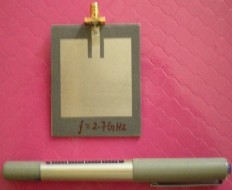
The scattering coefficients And, Ans, Bnd, and Bns, are obtained by invoking the boundary conditions on the lens surface for the total fields using the expressions (18)-(21). The fields Es and Ed scattered by the lens are found out by substituting these scattering coefficients in (1) and (2). Figure 9 shows the fields scattered by the lens, which are in close agreement with the fields obtained by direct aperture integration shown in Figure 6.
N m ax 30
i.e.
Nmax ceil[k * lensdia] which accounts for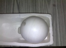
Figure 2a Rectangular Patch
about 99.9% of the energy.
The SMCCs an and bn of the primary radiator are computed using the field expressions (1) and (2) of the SME
model by exploiting the orthogonality properties of Mmn and Nnm[11]. The magnitudes of an and bn are shown in Figure 5 for 100 modes. The fast decay of the SMCCs indicates that most of the energy is concentrated in the first few modes (~5) where as the higher order modes contain negligible energy.
Using these SMCCs, the far fields of the rectangular patch are reconstructed by substituting them in expressions (1) and (2). The fields of the rectangular patch were also calculated using Aperture Integration Method [11]. There was a satisfactory match between the patterns obtained by the two methods as is evident from Figure 6.
As the phase centre of the dielectric lens is the reference
point for the analysis, the SMCC‗s obtained in the previous steps are subjected to the operation of radial translation using the equations (5) and (6) for a radial distance of
2.5cms.
As expected, the SMCCs decay fast indicating that the translation operation has not changed the energy content of the modes. The far fields are reconstructed again using the SME expressions (1) and (2), but with the translated SMCCs and are shown in Figure 7. The translated SMCCs are then spatially rotated using the rotation matrix to align them to the phase centre of the lens with the help of expressions in (11) and (12). The fields after the rotation operation are calculated by substituting the rotated SMCCs in expressions (1) and (2) and is shown in Figure 8.There is a reasonably close match between these fields and those in Figure 6.
Figure 2b Teflon Spherical Lens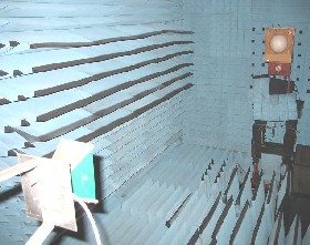
Figure 3 Lens Setup in an Anechoic Chamber
IJSER © 2011
International Journal of Scientific & Engineering Research, Volume 2, Issue 11, November-2011 5
ISSN 2229-5518
0
-5
-10
-15
-20
-25
-30
RETURN LOSS VERSES FREQUENCY
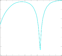
2 2.1 2.2 2.3 2.4 2.5 2.6 2.7 2.8 2.9 3
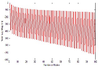
Figure 5 Plot of an and bn
FREQUENCY IN Hz
9
x 10
Figure 4 Return Loss of the Patch Antenna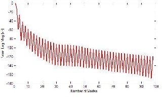
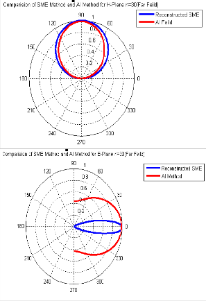
Figure 6 Far Fields calculated by SME and AI Methods (Initial Reconstruction)
IJSER © 2011
International Journal of Scientific & Engineering Research, Volume 2, Issue 11, November-2011 6
ISSN 2229-5518
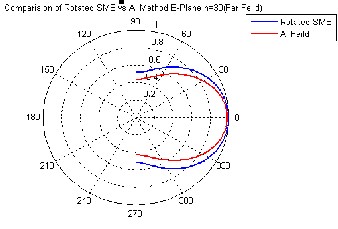
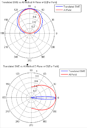 Figure 8 Far Fields after spatial rotation
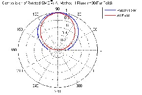
Figure7 Far Fields after linear translation 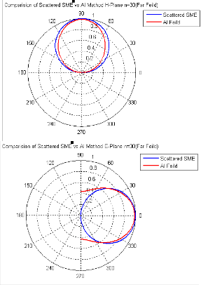
Figure 9 Far Fields after scattering
An analytically accurate and novel solution to the problem of prediction of radiation patterns of small aperture primary radiators in the presence of dielectric lenses has been presented. This uses Spherical Modal Expansion to characterize the primary radiator fields and the unknown scattered fields are obtained from a closed form solution for
IJSER © 2011
International Journal of Scientific & Engineering Research, Volume 2, Issue 11, November-2011 7
ISSN 2229-5518
spherically shaped lenses. The procedure involved translation and rotation of the primary radiator SME coefficients. The validity of this theoretical procedure has been demonstrated for a typical case of primary radiators like rectangular waveguide, small horns and patch arrays radiating in the presence of a Teflon spherical lens by comparing results with an experimental program. The analysis is easily applied to any type of radiating aperture
S.Ravishankar, received his Ph.D. degree in Electromagnetic Scattering from IIT Madras. His research interests are in the fields of Wire line Signal Processing Technologies, Electromagnetic Scattering and Antennas. He has published more
and any shaped dielectric lens.
[1] Carlos A Fernandes, ―Shaped dielectric lenses for Wireless Millimeter-
Wave Communicatiobs‖, IEEE Antennas and Propagation Magazine, vol
41, No 5, pp 141-150, October 1999.
[2] Leandro Fernandes, ―Developing a system concept & Technologies for Mobile Broadband Communications‖ IEEE Personal Communications Magazine, pp 54-59, Feb 1995.
[3] Carlos A Fernandes, Jose G Fernandes, ―Performance of Lens
Antennas in Wireless Indoor Millimeter Wave Applications,‖ IEEE
Transactions on Microwave theory and Techniques, vol 47, No 6, pp 732-
736, June 1999.
[4] William F Croswell, J S Chattejee, V Bradford Mason, ―Radiation from a homogeneous sphere mounted on a waveguide aperture,‖ IEEE Transactions on Antennas and Propagation, vol AP-23, No 5, pp 647-656, Sept 1975.
[5] H.S. Ho, C.J.Hagan, M.R. Foster, ―Microwave irradiation design using
dielectric lenses,‖ IEEE Transactions on Microwave theory and
Techniques, vol MTT-23, pp 1058-1061, Dec 1975.
[6] J. H. Bruning and Y.T. Lo, ―Multiple scattering of EM waves by spheres: Part I Multipole expansions and Ray optical solutions,‖ IEEE Transactions on Antennas and Propagation, vol AP-19, No 3, pp 378-390, May 1971.
[7] O.R. Cruzon, ―Translation addition theorems for spherical vector wave
functions,‖ Quarterly of Applied Mathematics, Vol20, No 1, pp 15-24,
1961.
[8] A.R. Edmonds, Angular Momentum in Quantum Mechanics, Princeton University Press, Princeton, 1974.
[9] S.Ravishankar and M.S. Narasimhan, ―Multiple Scattering of EM Waves by Dielectric Spheres located in the near field of a source of Radiation,‖ IEEE Transactions on Antennas and Propagation, vol AP-35, No 4, pp 399-405, April 1987.
[10] Julius Adam Stratton, Electromagnetic Theory, New York, McGraw
Hill Book Company, Chapter 7, 1941.
[l1] Constantine A Balanis, Antenna Theory - Analysis and Design, 2nd
Edn, Singapore: John Wiley and Sons: Chapter 12, 2002.
[12] Arthur Ludwig, ―Near–Field Far-Field Transformations Using
Spherical-Wave Expansions,‖IEEETrans. Antennas Propgat, vol.AP-19, N0.2, pp 214-220 March 1971.
than 25 papers in journals and international conference proceedings.
Prakash Biswagar is currently working as Associate Professor in the Department of Electronics and Communication Engineering at R V College of Engineering, Bangalore, India. He is currently pursuing his Ph. D degree in the field of Smart Antennas. His research interests are Antennas, Electromagnetics and Communication Systems
S. Shashidhar is pursuing his post graduate degree in Communication Systems at R V College of Engineering, Bangalore.
Authors may be contacted at
prakashbiswagar@rvce.edu.in
The authors sincerely acknowledge the financial support by ISRO (Indian Space Research Organization), Bangalore, India.
IJSER © 2011