International Journal of Scientific & Engineering Research, Volume 4, Issue 4, April-2013 1446
ISSN 2229-5518
A VHDL Implementation of Wireless Power
Transfer Technique on Mobile Robot Drive
System
K.Arun prakash,T.Angala parameshwari,K.Kokulavani
Abstract— The recharging system of a mobile robot must guarantee the ability to perform its tasks continuously without human intervention. Since mobile robots are powered by batteries, their energy and operating times are limited. Limited onboard power supplies significantly hamper long term autonomous mobile robot operation, particularly when working with swarm-sized populations. In this paper an efficient wireless power transfer system by running the vhdl code, that heats an IC which get connected to sensor that observes the heat and produces the electricity. The prototype consists of a power surface that provides power to an initial evaluation test robot consuming 350mW. An investigation on power transmission between a IC and sensor has carried out depending upon the alloy used. The power received is evaluated by the amount of heat that gets converted as electricity. Since Pyroelectricity is one of the form to generate the temporary voltage. W hether it is for business purposes or personal use, we need an efficient way of charging the battery of electronic drives. A possible application of this method includes powering of swarm
Index Terms— Charging of Mobile Robot, vhdl code, Pyroelectricity, Sensor Technique and W ireless Power Transfer.
1. INTRODUCTION
Mobile robots can be used in many missions such as surveillance, space and underground exploration, rescue assistance after disasters, etc [2-3]. As most mobile robots are powered by batteries, their energy and operation times are deficient. Therefore, how to minimize energy consumption and keep mobile robots stay alive becomes an important problem. Limited onboard power supplies significantly hamper long-term autonomous mobile robot operation, particularly when working with swarm-sized populations. In these situations, battery life usually varies depending on the activity level of each robot. This adversely affects researchers‟ ability to examine new algorithms and sensor systems both by creating troublesome logistical barriers and preventing the evaluation of large numbers of robots or algorithms with long running times.
K.Arun prakash is currently pursuing masters degree program in VLSI Design in Sri Eshwar College Of Engineering Affiliated To Anna University-Chennai, Tamilnadu, India, PH-8754237898.
E-mail: contactarun90@gmail.com
T.Angala parameshwari is currently pursuing master’s degree program in VLSI Design in Sri Eshwar College Of Engineering Affiliated To Anna University-Chennai, Tamilnadu, India
K.Kokulavani is currently pursuing masters degree program in VLSI Design in Sri Eshwar College Of Engineering Affiliated To AnnaUniversity-chennai,Tamilnadu,,India
The recharging system for a mobile robot must guarantee the ability to perform its tasks continuously without human intervention. To stay alive, the system need to guarantee that if a robot does not have enough energy, it should be able to return to a docking station for battery changing or recharging, which needs to be done in an energy- efficient way to save energy. Therefore, how to reduce energy consumption and keep mobile robots to stay alive becomes a crucial problem. Previous solutions in the literature have relied on battery exchange, docking or recharging schemes, or specialty power sources such as fuel cells.
In this paper, the research focuses on vhdl codes to heat an IC that get utilized by the sensors. The power received is to bring efficient drive system with long lasting performance. The design improves from previous literature [1] including a power management system and improves the power transmission, which gets, implemented to achieve a faster and more efficient drive system. As an illustration of long-term autonomy, the proposed system shows that, the robot is able to carry out a monitoring task for far longer than it would have been able to return for recharging.
IJSER © 2013
http://www.ijser.org
International Journal of Scientific & Engineering Research, Volume 4, Issue 4, April-2013 1447
ISSN 2229-5518
transfer. Resonant Inductive power transmission depends on a changing magnetic field that is usually generated by a power transmitting coil and a receiving coil in this magnetic field, where both operate at the same frequency. If the magnetic flux through the receiving coil is changed, a voltage will be induced in the receiving coil. The simplest way to generate a changing magnetic flux in the receiving coil is to actuate the transmitting coil by an alternating current.
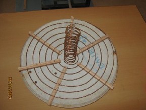
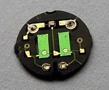
Fig.1 Circuit to produce the pyroelectricity
To realize the wireless energy supply, the microwave, the laser energy transmission is considered to be the most hopeful. The microwave energy transmission has an advantage of higher energy conversion efficiency and can be used through the cloud, but it is not easy to concentrate the power in a small region. The Laser method of power transfer requires an uninterrupted line of sight which cannot be used in underground exploration.
Recently, the use of a docking station has even been adapted to several commercial cleaning
robots. However, all docking stations which have been suggested by researchers and then commercialized suffer from the following three significant problems: (i) the low error tolerance of the docking mechanism, (ii) the low adaptability of the docking mechanism for various mobile robots as the most docking mechanisms are specifically designed to match the shape and size of their own robots, (iii) the requirement for the mobile robot to be shut down during recharging, turned on by the user and returned to the previous task after full recharging. These are impediments to the development of mobile robots as independent systems are able to perform tasks continuously without external assistance.
2. RELATED WORK
Many techniques have been developed to transmit power without wires. Each method has its own design, methodology, principle of operation and efficiency. The first method is Resonant Induction method of energy transfer is considered to be the effective one and this method is based on the principle of Resonant Induction energy
Fig. 2 Transmitting winding coil
The Fig.2 describes the process of sending electromagnetic waves in a highly angular waveguide, evanescent waves are produced which carry no energy. If a proper resonant waveguide is brought near the transmitter, the evanescent waves can allow the energy to tunnel to the power drawing waveguide, where they can be rectified into DC power. Since the electromagnetic waves would tunnel, they would not propagate through the air to be absorbed or dissipated, and would not disrupt electronic devices or cause physical injury like microwave or radio wave transmission.
Electromagnetic induction works on the
principle of a primary coil generating a predominant magnetic field and a secondary coil within that field, so that a current is induced within its coils. This causes a relatively short range due to the amount of power required to produce an electromagnetic field. The primary coil generates an electromagnetic field around its circumference. When the receiver coil operating at the same frequency comes into that field, magnetic field induces an alternating current in it. Over greater distances the non-resonant induction
IJSER © 2013
http://www.ijser.org
International Journal of Scientific & Engineering Research, Volume 4, Issue 4, April-2013 1448
ISSN 2229-5518
method is inefficient and wastes much of the transmitted energy just to increase range. It is
where the resonance comes in and helps efficiency dramatically by "tunneling" the magnetic field to a receiver coil that resonates at the same frequency. The receiving coils are single layer solenoids with closely spaced capacitor plates on the end, which in this combination allows the coil to be tuned to the transmitter frequency, thereby eliminating the wide energy wasting "wave problem" and allowing the energy to focus on a specific frequency increasing the range.
There are many docking techniques available to make robot to stay alive. One of the methods is autonomous docking with a recharging station that makes direct electrical contact with the robot. This method is commonly used in commercial robots such as robot’s. Because of the impracticality of simultaneously docking large numbers of robots, as would be required to dock and recharge an entire swarm at once, various battery exchange behaviors have also been explored. Unfortunately, these techniques still suffer from the inherent drawbacks of onboard battery power and inability to support continuous operation of the entire group of robots.
3. PROPOSED SOLUTION
The solution that this paper proposes is a complete system for the autonomous charging of a mobile robot’s motor. As for the charging procedures, we integrated the essential electrical circuits a solid and firm structure to supply the needed power. In the proposed method the VHDL code which is already located at the memory of swarm robot get induced for compiling by a signal from the docking systems which controls the mobile robot. This helps in identification of the charging condition of the drives. Docking system which has to controls all the drives when they are tends to do the research purposes. If any of the drives memory is corrupted the signal from the docking system are not loaded and utilized, so that the system is controlled and observed properly. The corrupted memory can also be corrected by the test vectors by wireless transmission.
There are many types of sensors that get used in transformation of heat energy to electrical
energy. Thus the highly sensitive sensors, which are of nano scale provides the high efficiency. The output and compatibility of the sensors are the major parameters which have to taken in account in the designing purpose. Electricity produced by the sensor, gets connected to the pins which absorbs and charge the robots. Since the basic concept is that the code gets executed by compiler and it is to be run continually for the finite number of time and that heats the sensor. The number of execution of the code depends on the size of the battery and the robot. The continual running should not affect the compiler and other library functions. The sensor placement is also a important factor, that they have to absorb the complete amount of heat.
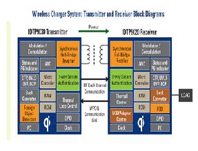
Fig.3 wireless transmission of power
4. DESIGN OVERVIEW
A. vhdl codes to heat an IC
There are two types of widely used hardware description languages i.e. Verilog HDL with C-language like syntax, easy to learn and another is VHDL which follows the structure of ADA programming language. Verilog and VHDL each have about 50% share of the commercial user base [8]. VHDL is acronym for VHSIC i.e. very large scale integrated circuit hardware description language. It was standardized by IEEE. VHDL is used for synthesis construct and implement a design on silicon. VHDL is used for simulation to imitate real world scenarios for verification. If you want to run the HDL simulator on the different drives. When both applications run on the same
IJSER © 2013
http://www.ijser.org
International Journal of Scientific & Engineering Research, Volume 4, Issue 4, April-2013 1449
ISSN 2229-5518
prototype, we have the choice of using shared memory or TCP sockets for the communication
channel between the two mobile drives. After coding one of the models’s components in VHDL or Verilog and simulate it in the HDL simulator environment, the integration part of the HDL with the specific IC’s which is ready to change its normal condition. Thus the atomic values get changed, which tends the IC to produce heat.
B. Program to heat a ASIC
TEMP_CSN : out std_logic;-- Temp Sensor SPI Select
-- TEMP_SCK : out std_logic;-- Temp Sensor SPI Clock
-- TEMP_SDO : inout std_logic;-- Temp Sensor SPI
Data
process (Clk, Rst)
variable BitCnt : integer range 0 to 16;
begin
if Rst='1' then
in...
TEMP_CSN <= '0'; TempH <= (others=>'0');
TempL <= (others=>'0'); BitCnt := SPi_Nbits; stSPI <= spiRead1;
end if;
when spiRead1 =>
if Tick4us='1' then
TEMP_SCK <= '1'; -- rising edge stSPI <= spiRead2;
if BitCnt = SPi_Nbits then
Sign <= FPGA_uW_SIOr; -- Shift the sign
if Tick4us ='1' then TEMP_SCK <= '0'; if BitCnt /= 0 then
stSPI <= spiRead1; else -- No more bit TEMP_CSN <= '1';
if Cnt05s(Cnt05s'high) = '0' then
WrTemp <= '1'; -- signal we want to
WrTemp <= '0';
TEMP_CSN <= '1';
TEMP_SCK <= '0';
Sign <= '0';
stSPI <= spiBoot;
BitCnt := 0; FPGA_uW_SIOr<= '0'; TempH <= (others=>'0'); TempL <= (others=>'0');
elsif rising_edge (Clk) then
WrTemp <= '0';
FPGA_uW_SIOr <= TEMP_SDO or TEMP_SDO;
case stSPI is
when spiBoot =>
if Tick4us='1' then
stSPI <= spiIdle;
end if;
when spiIdle => TEMP_CSN <= '1'; TEMP_SCK <= '0';
if Cnt05s(Cnt05s'high) = '1' then -- read
temperature ~ 2 times / s
display the temp
stSPI <= spiIdle;
end case;
end if;
end process;
end block;
C. pyroelectricity and power generation
Pyroelectricity can be visualized as one side of a triangle, where each corner represents energy states in the crystal: kinetic, electrical and thermal energy. Although artificial pyroelectric materials have been engineered, effect was first discovered in minerals such as tourmaline. These materials are said to exhibit ferro electricity. All pyroelectric materials are also piezoelectric, the two properties being closely related. However, note that some piezoelectric materials have a crystal symmetry that does not allow pyroelectricity. Very small changes in temperature can produce an electric potential due to a materials' pyroelectricity. Progress has been made in creating artificial pyroelectric materials, usually in the form of a thin film, out of gallium nitride (GaN), cesium nitrate (CsNO3), (LiTaO3) is a crystal exhibiting both piezoelectric and
IJSER © 2013
http://www.ijser.org
International Journal of Scientific & Engineering Research, Volume 4, Issue 4, April-2013 1450
ISSN 2229-5518
pyroelectric properties, which has been used to create small-scale nuclear fusion ("pyroelectric
fusion").
The pyroelectric coefficient may be described as the change in the spontaneous p temperature

Where pi (Cm-2K-1) is the vector for the pyroelectric coefficient.
Possible advantages of pyroelectric generators for generating electricity include potentially lower operating temperatures, less bulky equipment, and fewer moving parts.
D.Adaptations of sensors
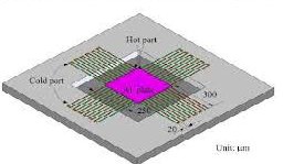
into electrical power using a thin, nano scale
Fig.4.Schematic of Thermoelectric micro generator
Material which positions it to address market opportunities that standard bulk thermoelectric devices and other energy scavenging or energy reclamation systems. Nextreme’s eTEG devices generate electricity via the See beck Effect where a voltage is produced from the temperature differential produced by heat flow through the device.
The multi ferric alloy, with the catchy name Ni45Co5Mn40Sn10, was created by combining its various elements at the atomic level. Multi ferric materials are known for having unique elastic, magnetic and electric properties, and in the case of this alloy, that takes a form of an usual phase change. When heated, the non-magnetic solid material suddenly becomes a strongly magnetic solid. the material absorbed heat in its environment and proceeded to produce electricity in an attached coil. Nextreme’s thin film thermoelectric materials deliver the world’s smallest thermoelectric generator (eTEG) with the highest output power density. Optimized to provide power for high heat fluxes (>20 W/cm²), Extreme’s eTEG enables convenient conversion of heat to electrical power in a very thin, lightweight form factor. Five to 20 times thinner than conventional bulk thermo electrics, Extreme’s thin- film thermoelectric materials convert waste heat
TABLE I
Electrical Properties (as a generator)*
Power** | 13 Watts | Minimum |
Load Voltage | 1.65 Volts | ±0.1 |
Internal Resistance | 0.15 Ohm | ±0.05 |
Current | 8 Amps | ±1 |
Open Circuit Voltage | 3.5 Volts | ±0.3 |
Efficiency | 4.5 % | Minimum |
5. RESULT AND DISCUSSION
The temperature produced by the ASIC (Spartan family), gets observed by the sensors completely and the process of conversion of heat to electrical energy gets regulated. Since the process begins when the charge of the mobile robots get utilized for their purposes. As the heat dissipated at the time of the usage of the charges get noted and that heat also get converted to charge the mobile robots. By increase of the temperature the output of sensor is also increasing. Though various other techniques is also used in charging the drives but if the drives are not controlled by the docking system then the total process is of waste. By the VHDL code which is already present at the mobile robot it can be executed easily. In case of drives lose its control from the docking system, the heat that dissipated from the battery of the mobile drive heats a sensor and so it gets activated again.
IJSER © 2013
http://www.ijser.org
International Journal of Scientific & Engineering Research, Volume 4, Issue 4, April-2013 1451
ISSN 2229-5518
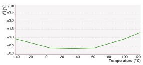
Fig.5 Representation of usage of temperature
A new power generation technology that uses heat as a source of electricity for low-power wireless applications. Electrical connections can be made using the on-board 2-pin or 6-pin connectors. The
6-pin connector is a Texas Instruments connector
that mates to the eZ430 wireless target board, making the WPG-1 an ideal wireless power source for the eZ430 development platform. The power transmission efficiency was estimated by comparing the generated heat of ASIC and the output power of the sensor.
6. CONCLUSION
The test results showed that the wireless power transmission system can supply relatively constant power throughout a large working area. Multiple times of execution of the VHDL code to charge the single mobile robot, avoids the wastage of time. As a cost of these features, this power transmission system has a relatively reasonable efficiency. This method gives a positive result both in long run and in expense. By properly selecting the sensor and thermo diode which is of appropriate sensitivity, size will bring up the efficiency. From the experimental set up the following observations has been made. It is estimated that the cost of the power reception and conditioning circuitry on the swarm robot to be approximately $2.00 per robot. This can be compared very favorably with the cost of lithium ion batteries and their associated charge control circuitry. The achieved result shows an unlimited long run time of the autonomous vehicle through wireless energy transfer thereby bringing up a new trend in the enhancement of robot performances. If the system is designed for many small sized robots like swarm robots, the use of batteries and can be eliminated there by cost is minimized. It also
provides an eco friendly environment. Hence this method makes the mobile robot to involve
in all rescue operation and investigation areas with long run-time performance.
7. REFERENCES
1. Karalis, Aristeidis, J. D. Joannopoulos and Mar in Soljačić,
„Wireless Non-Radioactive Energy Transfer‟, Annals of
Physics 323, pp. 34–48 (2008).
2. Gao.J, „Inductive power transmission for untethered micro-robots‟, 31st Annual Conference of IEEE Industrial Electronics Society (IECON), pp. 6–11 (2011).
3. Sedra.A.S and Smith.K.G. “Micro-Electronic Circuits”,
Oxford University, Newyork, 2004.
4. Hagerty.J.A. “Nonlinear Circuit and Antennas for
Microwave Energy Conversion”, University of Colorado,
2009
5. Pylarinos.L and Roger.E, “Charger Pumps: An Overview”, Department of Electrical and Computer Engineering, University of Toronto.
6. R. D. Hunt, Patent No. WO2004004016-A1, January 8,
2004.
7. N i k o l a T e s l a , “ T h e t r u e w i r e l e s s ” , E l e c t r i c a l E x p e r i m e n t s , M a y , 2 0 0 0 .
IJSER © 2013
http://www.ijser.org