International Journal of Scientific & Engineering Research, Volume 4, Issue 7, July-2013 109
ISSN 2229-5518
A Survey on Free -Standing Phase Correcting gain enhancement Devices
Neha Singh, Kamal Kishor Choure, Meenu Kumari
Abstract— Free-standing phase-correcting structures are very useful devices for various antenna applications. These devices are usually required to modify the incoming beam from a feeder antenna and transform it to obtain high gain or gain enhancement. The gain of any antenna is directly proportional to the aperture size of that antenna. For gain enhancement, we have to increase the aperture size. Generally this is done by introducing a device of size larger than the feed antenna. The best known application is the reflector antenna. Lens antennas are another example. Lens antennas are also operating like a reflector but in transmission.
Gain of an antenna is also increased by using multiple antenna elements in an array configuration. Phasing is an important parameter for these kinds of devices. Maximum broadside gain is achieved with uniform phasing. When such type of control is possible, uniform amplitude as well as a uniform phase will ensure a maximum antenna gain. If we want shaped beam to achieve some specifications, then amplitude and phase can be varied at the price of a gain penalty.
This paper focuses on various type of free-standing phase correcting devices of the transmissive type. Although they look physically different, but they have the same operation principle of gain enhancement and phase correction of electromagnetic waves which are propagating through them.
Index Terms— Phase correction, Reflector antenna, Spherical wave, Zoning, Artificial dielectric, Transmitarray, Phase shifting surface lens antenna,
1. Introduction
—————————— —————————
Email: nehasingh_ch@yahoo.com
For transmitting or receiving energy, in advanced wireless system an antenna is required to optimize the radiation energy in desired directions and suppress energy in undesired direction. Thus the antenna must also have a directional property [1].
The gain of any antenna is directly proportional to the size
of aperture of that antenna. For gain enhancement we have to increase the aperture size. This is done by using a device of larger size than the feed antenna. The best application for gain enhancement is the reflector antenna. In place of reflector, lens antennas can also used. Another way of gain enhancement of any antenna is by using multiple antenna elements in an array configuration. But implementation of array is very high cost, for that reason, their use is very limited. This paper focuses on free-standing phase correcting devices of the transmissive type. The most common phase correcting devices are lenses. Various type of lens is used, they look physically different, but their operating principle is same.
Lenses have many advantages over reflecting structures;
that’s why instead of reflector antenna, lens antennas are
used. Lens has no feed blockage and very high fabrication tolerances as compare to reflectors [2].
Now day’s millimeter wave applications are rapidly increasing in wireless systems such as radio astronomy and image sensing radiometer. At these frequencies lens antennas are become acceptable in size and weight for many applications [3].

Neha Singh, Kamal Kishor Choure, and Meenu Kumari are currently pursuing MTech Degree in Electronics and Communication department.
At high frequency, the lens antenna is usually preferred because of its small size, less weight and high gain enhancement capacity. Lens antenna also used to increases
the directivity of the overall antenna system. Directivity of the any antenna depends on size of the antenna and relative dielectric permittivity of the material. Directivity is increased with antenna size [4].
Lens antenna system composed by two things: the feeder antenna and lens. Feeding antenna can be any type of antenna or antenna array that collimates incident divergent energy to arising it from spreading in undesired directions. Various types of feeding antennas are used for lenses, such as dipoles, horns, and dielectric rod antenna [3].
2. Feeder Antenna Description
The horn antenna is widely used as a feeder antenna for radio astronomy and satellite tracking. The horn antenna is nothing just a hollow pipe of different cross sections [1]. Horn and lens combination is a small part of a larger quasi optical system. Horn and lens combination is basic starting point for designing quasi-optical systems [5].
The size of the horn antenna is based on the operating
frequency range and desired application [6]. The horn is
widely used as a feeder antenna because of its various advantages. A horn can support the balanced hybrid HE11 - mode, and exhibits low cross polarization and also low side lobes over a wide frequency range [7].
At millimeter wavelengths, antennas which are physically
small can radiate relatively narrow beams. Such antennas
IJSER © 2013 http://www.ijser.org
International Journal of Scientific & Engineering Research, Volume 4, Issue 7, July-2013 110
ISSN 2229-5518
are very well suited for miniaturized transceivers. Other antennas can also used as a feeder such as microstrip patch arrays, but their efficiency decreases with increasing
frequency .Waveguide-based slot arrays can also used, but
they require expensive, tightly tolerance machining to fabricate. So we can say that conventional horn antennas are an inexpensive alternative [8].
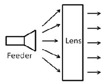
Fig. 1 A lens antenna with feeder horn
3. Lens Antenna Description
By properly shaping, and choosing the proper material of the lenses, they can transform spherical wave into plane waves. Classification of lens antennas are done on the basis of their shape and material from which they are constructed [1]. For microwave applications, lens antenna is used to converge radiation to or from a source antenna known as the feed. The lens and the feed together create a large aperture or high gain antenna. When the lens antenna is in transmitting mode, it focuses the radiation from the feed into a narrow beam; when lens is in receiving mode, the lens focuses the incident field from the aperture into the feed [9].
The lens antenna is designed to create equal electrical path lengths between a planar wave front and a focal point. At microwave frequencies, dielectric lens antenna can be formed from bulk materials or artificial materials. An artificial dielectrics material consist of a lattice of discrete metal particles, e.g., metal strips, rods and many more [9]. Lens antenna can also used in quasi-optical systems to correct the phase errors of feeder antennas [10]. Lens offer some advantage over reflectors such as high efficiency, no feed blockage, and reduced sensitivity to manufacturing tolerances [11].
These properties of lenses are very useful for higher
frequency designs. However, microwave lenses have a major disadvantage in terms of weight and thickness because of small value of F/D (Here F is focal length and D is diameter of lens) [2].
In next section we discuss various types of lens antenna
with their advantages, disadvantages, and limitation.
4. Types of lens antenna
In this section we discuss various type of lens antenna which are used for phase correction and gain enhancement.
4.1 Dielectric Plano hyperbolic lens antenna
(DPHLA)
The primary objective of designing DPHLA has been the development of such antenna which minimize the radiated signal levels outside the main beam region, with low levels of far-out-side lobe and back lobe regions. Low levels in these regions are particularly important in applications requiring minimization of interference [12].
The DPHLA (shown in Figure 2, where D is diameter of
DPHLA and t is total thickness of DPHLA) is designed
using a well known expression for single-surface lenses given in the literature [13].
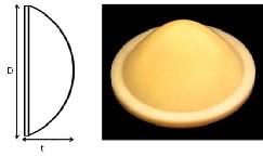
Fig. 2 Dielectric Plano hyperbolic lens antenna (a) side view and (b) front view [2]
DPHLA provide high gain, and large operating bandwidth. DPHLA has a big disadvantage that its thickness is very large so that it is not suitable for many applications, that’s why a new lens antenna called phase correcting Fresnel zone plate (PC-FZPA) is designed for removing the disadvantage of Dielectric Plano Hyperbolic Lens Antenna.
4.2 Phase correcting-Fresnel zone plate antenna
(PC-FZPA)
To reduce the weight of large lenses, some portion of the lens can be removed and creating a new lens which is known as phase correcting Fresnel zoned plate lens antenna (PC-FZPA). Zoning removes material in multiples of one wavelength, so that phase of the electrical path length is unchanged. Since the shape of the lens is referenced to a specific wavelength, zoned lenses are frequency dependent. Zoning also introduces some diffraction in the lens [9].
The idea of a phase-correcting zone plate, based on
Fresnel’s zone method, was presented by Lord Rayleigh
IJSER © 2013 http://www.ijser.org
International Journal of Scientific & Engineering Research, Volume 4, Issue 7, July-2013 111
ISSN 2229-5518
[14], when he introduced a method to improve the focusing ability of the zone plate described by Soret [15]. Instead of blocking the incident field in alternating Fresnel zones as Soret did, Rayleigh suggested that the phase of the incident field in these zones be reversed. This technique allows the entire full-wave Fresnel zone to contribute to the focusing, instead of only half of each zone, as is the case for the Soret- type zone plate.
A telescope using a zone plate designed in this manner was
constructed by Wood [16]; a contribution that has been acknowledged by frequent use in the literature of the term Wood-type zone plate to refer to a phase-correcting zone plate [17]. Extending this logic and subdividing the Fresnel zones to correct the phase of electromagnetic wave in finer increments results in a zone plate that should have improved focusing ability [18].
Zone plate antenna cannot design without any drawbacks.
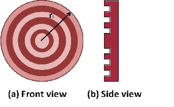
The most common drawbacks of these antennas are their limited bandwidth with thickness reduction [19]. As diffractive devices, zone plate antennas are designed to work at one particular frequency, if PC-FZPA use at another frequency than its performance degrades. Zone plates offer less weight, this make them especially well- suited for use at low frequencies [20]. Phase correction may be 45°, 90° or 180°. For 45° phase correction P=8, for 90° phase correction P=4 and for 180° phase correction P=2. For P=2 PC-FZPA shown in Figure 3, where ri is radius of each zone.
PC-FZPA have advantage over DPHLA in terms of
thickness, it also have a disadvantage over DPHLA in terms of bandwidth. PC-FZPA becomes more and more band limited with reduction in thickness.
Fig. 3 Phase correcting-Fresnel zone plate antenna for P=2
4.3 Metallic waveguide lens
In the middle of the twentieth century, Kock introduced metallic waveguide lens antennas [21] consisting of parallel conducting plates used as hollow waveguides to control the phase velocity of the electromagnetic waves propagating
through the plates. These are of two types E-Plane and H- Plane. E-Plane type of metallic waveguide lens antenna is shown in figure 4 [22], where t is thickness of metallic plates.
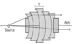
Fig.4 E- Plane type of Metallic waveguide lens [22]
In this configuration the wave passing through the plate has a higher phase velocity than free-space velocity, which is opposite to that of dielectric materials for which the phase velocity is lower than in free-space. The motivation behind the use of metallic waveguides is to reduce the weight of microwave lenses. However, they suffer from thickness issues, bandwidth limitations and polarization sensitivity [21, 23].
4.4 Artificial dielectric lens
Another very important concept for phase correction is given by Kock which is artificial dielectric lenses [21]. The concept of artificial dielectric has also well documented by Cohn in [24]. Artificial dielectric lens are used for forming various artificial surfaces, e.g., high impedance surfaces, and anti reflection coatings [25]. The main application of artificial dielectric lens was to replace the heavy dielectric material in lens antennas [26].
Artificial dielectrics lens consist of a series of thin, and parallel dielectric layers containing two-dimensional arrays of small metallic implants, whose size and spacing are small compared to the wavelength. The size of the metallic implants and their spacing is designed in such a way that desired effective dielectric constant is achieved.
A lens designed by this concept requires many dielectric
layers. It is not thinner as compare to other conventional
lens, but can be lighter than solid dielectric because of light- weight material. Kock’s idea was to produce the higher relative permittivity by inserting metallic implants (thin strips or disks) within a dielectric host of lower relative permittivity, generally foam ( εr ≈ 1) is chosen. The gain enhancement and phase correction is achieved by shaping the thick artificial dielectric in the same way as conventional lens is shaped to traditionally form a hyperbolic lens shape [2].
IJSER © 2013 http://www.ijser.org
International Journal of Scientific & Engineering Research, Volume 4, Issue 7, July-2013 112
ISSN 2229-5518
As we know that Foam is a very light material, the advantage is a significant weight reduction, but thickness is very large. Figure 5 presents a prototype of an artificial dielectric lens of metal spheres and metal strip, where w is width of metal strip. An artificial dielectric which presents variable metallic implants throughout the aperture of the lens is used to design a lens. A single layer of implants was not enough to provide sufficient phase correction; many layers were inserted in cascade, spaced by thick layers of low dielectric constant. Although this results in a flat lens, the thickness remains particularly high [27].
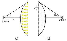
Fig. 5 Artificial dielectric lens antenna of (a) metal spheres and (b) metal strip
4.5 Flat lens antenna using microstrip patches
A very limited research has been carried out for reducing the thickness of phase-correcting lenses. The first thin, flat phase-correcting device was introduced in 1986 by McGrath [29] and it was revisited in 1996 by Pozar [30]. McGrath introduces a design for a three-dimensional discrete-element lens whose front and back surfaces are planar. The concept of flat lens is to use front and back layers of resonant microstrip patch antennas connected by varying lengths of transmission lines. The length of the transmission lines is carefully adjusted at every location on the plane surface of the layer in order to perform an overall lens function, i.e. to obtain the desired phase correction between the incoming and outgoing wave fronts. This is a thin, single-piece free- standing device that uses mature fabrication technique i.e. called photolithographic (wet chemical) etching process.
This thin lens device suffers from two major drawbacks i.e.
increased complexity of fabrication, or a large number of layers, and high quantisation error because a single patch antenna occupies large area of the lens aperture [30]. Patch size of microstrip antenna is on the order of half a guided wavelength, and the separation between two patches has to be less than half a free-space wavelength to avoid grating lobes. The main disadvantage of high quantisation error is reduction in the overall aperture efficiency of the lens antenna. The reflection loss, transmission line loss and
bandwidth limitation are also some another drawback of patch antenna which make it unsuitable for various millimeter wave application. The design element and interconnection for a microstrip constrained lens introduced by McGrath is presented in Figure 6.
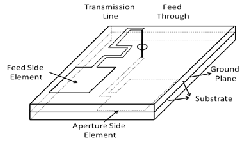
Fig. 6 Design element for realising a flat lens antenna using microstrip patches [29] .
4.6 Transmitarray
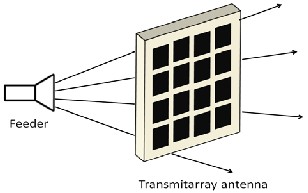
A transmitarray is a free-standing device that is composed of an array of multiple discrete elements; it is used as a transmitting device. The name of transmitarray is inspired from the reflectarray, but is used as a transmitting surface rather than a reflective surface. As a reflectarray can replace a conventional reflector, a transmitarray can also replace a conventional lens. A single layer is not enough to provide a broad range of phase shift; as a result, many layers need to be cascaded [31].
A transmitarray antenna is combination of two antennas i.e. lens and phased array. Unlike the reflectarray antenna that the electromagnetic wave reflects from the surface, transmitarray transmits through the surface. The feeder antenna (generally horn) is located behind the surface and the configuration looks like a lens antenna setup as shown in Figure 7. The advantage of transmitarray is the preservation of the symmetry of antenna aperture [32]. A transmitarray for single-band and dual-band, which consisting of few dielectric sheets where the constitutive layers are inspired by frequency-selective surface (FSS) elements is presented in [33]. Transmitarray is thinner than a traditional dielectric lens; but it have one major drawback with current transmitarray designs is the requirement of air gap between dielectric layers in order to maximize gain. This does not allow for achieving an optimum thickness reduction [2].
IJSER © 2013 http://www.ijser.org
International Journal of Scientific & Engineering Research, Volume 4, Issue 7, July-2013 113
ISSN 2229-5518
Fig. 7 A transmitarray antenna [32]
4.7 Phase correction- Phase shifting surface- Lens antenna (PC-PSS-LA)
It is well known that the physical size of antenna for achieve a given phase shift is proportional to the wavelength, assuming that the dielectric constant or index of refraction is unchanged. As the wavelength is increased, the physical size of the phase shifting device will increase proportionally, leading to bulky designs at microwave and millimeter wavelengths. That’s why a new concept is required for designing light weight lens antenna which is known as PSS [2].
The Phase shifting surface (PSS) concept can be used to
design antennas. PSS is used to design a thin Lens antenna called Phase Shifting Surface Lens Antenna (PSS-LA). As its name suggests, phase shifting surface (PSS) is a free- standing surface that allows for controlled or changing of the phase of an electromagnetic wave which is propagating through it.
In order to achieve gain enhancement, the PSS is made non-
uniform, it means every location on its surface has to
provide different phase shifts. In PSS a dielectric surface is divided into a rectangular or square lattice of unit cells and each unit cell have a metallic patch (as shown in figure 8, where c is cell size, p is metallic patch, and g is gap between two patches) which provide a predetermined amplitude weighting and phase shift. For this reason, the unit cell parameters are of great importance since the combination of these physical parameters leads to different phase (and/or amplitude) shift.
In place of small rectangular or square lattice of unit cells a continuous large rectangular cells (continuous in X axis) are used (as shown in figure 9); to save simulation time and RAM memory. A single metallic layer not provide a complete phase shift of 3600 ; that’s why 3 metallic layers are used in z direction which provide a phase shift of 3050. Almost perfect transmission is realized for 3000. That’s why usually 3 metallic layers are used for designing PSS-LA [2], Shown in figure 10. After designing PSS-LA, phase correction concept (P=2, P=4, or P=8 any type of phase
correction can apply) is applied in it, and it become Phase correction-Phase shifting surface-Lens antenna (PC-PSS- LA) shown in figure 11 [34]. PC-PSS-LA is very recent research to increase the gain of feeder antenna, it is very thin as compare to other lens devices, its thickness is of order of 0.1λ₀ - 0.2λ₀, and its bandwidth performance is also good.
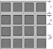
Fig. 8 Front view of the square uniform periodic structure composed of square unit cells with square metallic patches (the dielectric is shown in light colour and the metal is shown in dark colour by hatched line) [2].
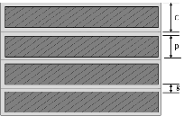
Fig.9 Front view of the uniform periodic structure composed of strip elements [2]
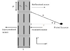
Fig. 10 PSS-LA side view with three metallic layers
IJSER © 2013 http://www.ijser.org
International Journal of Scientific & Engineering Research, Volume 4, Issue 7, July-2013 114
ISSN 2229-5518
Fig. 11 PC-PSS-LA for 900 phase correction made by using
3 metallic layers [34]
5. Conclusion
The main objective of using lens antenna is to get high gain or gain enhancement. Lens and feeder antenna combination is very important part of wireless communication. In this paper, background information relevant to the work on gain enhancement with phase correction, phase transformation or phase shifting was presented. In this paper, the work on various lens antenna technologies, including the work on dielectric plano hyperbolic lens, phase correction Fresnel zone plate antenna, metallic waveguide lens, artificial dielectric lens, flat lens antenna using microstrip patches, transmitarray, and phase shifting surface lens antenna was reviewed. Advantages, disadvantages and application of each lens are also discussed. From above discussion we know that best lensing device for getting high gain with no bandwidth limitation is DPHLA (when thickness is not matter), but when thickness of lensing device is matter than PSS-LA is good choice for getting high gain with large operating frequency band .
References
[1] Constantine A. Balanis, “Antenna theory’’ John Wiley & Sons Third edition 2005
[2] N. Gagnon, “Phase Shifting Surface (PSS) and Phase and Amplitude Shifting Surface (PASS) for Microwave Applications” PhD Thesis submitted in university of Ottawa, Canada, 2011
[3] J. P.Thakur, W.G. Kim, and Y.H. Kim, “Large Aperture
Low Aberration Aspheric Dielectric Lens Antenna For W- Band Quasi- Optics ’’ Progress In Electromagnetics Research, PIER 103, 57-65, 2010
[4] A. Karttunen, J. Ala-Laurinaho, R. Sauleau, A.V. Raisanen, “Reduction Of Internal Reflections In Integrated Lens Antennas For Beam-Steering” Proc. 4th European
Conference on Antennas and Propagation, Barcelona, Spain, Apr. 12–16, 2010, p. 1.
[5] Jussi Tuovinen, Taavi M. Hirvonen, and Antti V. Raisanen, “Near-Field Analysis of a Thick Lens and Horn Combination: Theory and Measurements” IEEE transactions on antennas and propagation, vol. 40, no. 6, june 1992
[6] Xu Li, Susan C. Hagness, Min K. Choi, and Daniel W. van der Weide, “ Numerical and Experimental Investigation of an Ultrawideband Ridged Pyramidal Horn Antenna With Curved Launching Plane for Pulse Radiation” IEEE antennas and wireless propagation letters, vol. 2, 2003
[7] ERIK LIER, “A Dielectric Hybrid Mode Antenna Feed:
A Simple Alternative to the Corrugated Horn” IEEE transactions on antennas and propagation, vol. ap-34, no. 1, january 1986
[8] Eric L. Holzman, “A Highly Compact 60-GHz Lens- Corrected Conical Horn Antenna” IEEE antennas and wireless propagation letters, vol. 3, 2004
[9] Rudi Henry Phillion “Flat Lenses for Circularly
Polarized Electromagnetic Waves” PhD Thesis submitted in
Calgary, Alberta December, 2010
[10] Patrik Pousi, “Active And Passive Dielectric Rod
Waveguide Components For Millimetre Wavelengths” PhD Thesis submitted in Aalto University Espoo, November
2010
[11] R.J. Dewey, “Reflector And Lens Antennas For Millimetre-Wave Radiometers”, IEEE Microwave Conference, 1981, 11th European pages 573-578
[12] H. Paris Coleman, Russell M. Brown and Bill Dy.
Wright “Low Sidelobe Antennafso R Millimeter Wave
Communications Systems”, IEEE Antenna and Propagation Society International Symposium, June 1975 pages 240-243 [13] P.F. Goldsmith, “Quasioptical Systems” IEEE Press, New York, NY, 1998
[14] L. Rayleigh, “Wave theory,” in The Encyclopædia
Britannica, 9th ed. New York: Henry G. Allen and Co.,
1888, vol. 24, pp. 428–429.
[15] J. L. Soret, “Ueber die durch kreisgitter erzeugten diffractions phänomene,” Ann. Phy. Chem., vol. 156, pp.
99–113, 1875, Reprinted in J. Ojeda-Castañeda and C. Gòmez-Reino, Eds., Selected Papers on Zone Plates. Bellingham, WA: SPIE, 1996, pp. 11–25.
[16] R. W. Wood, “Physical Optics”, 3rd ed. New York: Macmillan, 1934.
[17] H. D. Hristov, “Fresnel Zones inWireless Links, Zone
Plate Lenses, and Antennas” Boston, MA: Artech House,
2000.
[18] F. Sobel, F. L. Wentworth, and J. C. Wiltse, “Quasi- optical surface waveguide and other components for the
100- to 300-Gc region,” IRE Trans. Microw. Theory Tech., vol. MTT-9, pp. 512–518, Nov. 1961.
IJSER © 2013 http://www.ijser.org
International Journal of Scientific & Engineering Research, Volume 4, Issue 7, July-2013 115
ISSN 2229-5518
[19] J. E. Garrett and J. C. Wiltse, “Fresnel zone plate antennas at millimeter wavelengths” Int. J. Infrared Millimeter Waves, vol. 12, no. 3, pp. 195–220, Mar. 1991
[20] David R. Reid and Glenn S. Smith “A Comparison of
the Focusing Properties of a Fresnel Zone Plate with a Doubly-Hyperbolic Lens for Application in a Free-Space, Focused-Beam Measurement System” IEEE transaction on antennas and propagation, vol.57, no. 2, February 2009
[21] W.E. Kock, “Metal-Lens Antennas,” Proceedings of the
IRE, vol. 34, no. 11, pp. 828-838, November 1946.
[22] John D. Kraus, Ronald J. Marhefka “ Antennas for all
application” third edition 2004 TaTa McGRAW-HILL
EDITION
[23] Andrey A. Nosich, Ronan Sauleau, Akira Matsushima,
Yuriy V. Gande, “Accurate modeling and optimization of metallic-plate waveguide lenses ” IEEE Antennas and propagation, 2009, EuCAP March 2009
[24] S.B. Cohn, “Artificial Dielectrics for Microwaves,” in Proceedings of the Symposium on Modern Advances in Microwave Technique, New York, NY, November 1954.
[25] Jan Machac, “Microstrip Line on an Artificial Dielectric
Substrate” IEEE Microwave And Wireless Components
Letters, Vol. 16, No. 7, July 2006
[26] L. Thourel, “The Antenna,” Wiley, Hoboken, NJ, 1960.
[27] C. Abella et al., “Artificial Dielectric Lens Antennas: Assessment of their Potential for Space Applications,” in
23rd European Microwave Conference, Madrid, Spain, pp.
896-898, September 1993.
[28] A. Petosa, A. Ittipiboon, S. Thirakoune, “Design and
Performance of a Perforated Dielectric Fresnel Lens,” IEEE Proceedings on Microwaves, Antennas and Propagation, vol. 150, no. 5, pp. 309-314, October 2003.
[29] D.T. McGrath, “Planar Three-Dimensional Constrained Lens,” IEEE Transactions on Antennas and Propagation, vol. 34, no. 1, pp. 46-50, January 1986.
[30] D.M. Pozar, “Flat Lens Antenna Concept Using
Aperture Coupled Microstrip Patches,” IEE Electronics
Letters, vol. 32, no. 23, pp. 2109-2110, November 1996.
[31] M.R. Chaharmir, A. Ittipiboon, J. Shaker, “Single-Band
and Dual-Band Transmitarray,” in 12th International Symposium on Antenna Technology and Applied Electromagnetics (ANTEM 2006), Montréal, Canada, pp.
491-494, July 2006.
[32] King-wai Lam, Sze-wai Kwok, Yeongming Hwang and
Terry Kin-chung Lo, “Implementation Of Transmitarray Antenna Microstrip Patches Concept By Using Aperture- Coupled”, Asia Pacific Microwave Conference, 1997
[33] C.G.M. Ryan, et al., “A Wideband Transmitarray Using
Dual-Resonant Double Square Rings,” IEEE Transactions
on Antennas and Propagation, vol. 58, no. 5, pp. 1486-1493, May 2010.
[34] N. Gagnon, Aldo Petosa, and Derek A. McNamara
“Comparison between Conventional Lenses and an
Electrically Thin Lens Made Using a Phase Shifting Surface (PSS) at Ka Band”, Loughborough Antennas & Propagation Conference 16-17 November 2009, Loughborough, UK
IJSER © 2013 http://www.ijser.org