International Journal of Scientific & Engineering Research, Volume 3, Issue 11, November-2012 1
ISSN 2229-5518
Manu GV, Namratha M, Pradeep
ABSTRACT
The aim of this paper is to design a simulator which helps in monitoring and controlling the system at INC (IRNSS
Navigation Center) for IRNSS. The simulator visualizes the working of various ground segment elements. W e design and develop an indigenous, independent satellite based regional navigational system under Indian control catering to various national needs. It should provide accurate position, navigation and time (PNT) to the user with following specifications accuracy better than 20 meter in horizontal and vertical position within the service volumeand time better than 20 nano seconds. Provide navigation services over the Indian landmass and surrounding areas extending to 15000 kilometers beyond its geopolitical boundaries.Expand service area subsequently, to an area bounded by 40deg S and 50deg N latitude. Housekeeping and navigation operations by establishing control centers and uplink/downlink facilities and established dedicated two way ranging system for validating one way are the configuration objectives..
Keywords: INC, IRNSS, Layered Architecture, Sequence diagram, Ground segment, Space segment, User segment
I. INTRODUCTION
The proposed architecture of the IRNSS[1],[4],[5] consists of space segment, ground segment and user segment. The space segment consists of three GEOs located at 34° E, 83° E and 132° E and four GSOs. The 4 N-GSOS will be placed in the orbit at an inclination angle of 29° with longitude crossing at 55° and 111° East. The ground segment consists of IRNSS ranging and integrity monitoring which will be located at 20 places and most of them will be located in the airports along with GAGAN ground elements. IRNSS will have the two Master Control Stations (MCS), which may be co-located with GAGAN. The intended coverage area for IRNSS has been proposed to be over the Indian subcontinent and service area will be primarily on the Indian land mass and adjoining areas. The service area for IRNSS is specified as between longitude 40oE to 140o E and between latitude
± 40o.
————————————————
Manu G V is currently pursuing masters degree program in Computer Science, SJCIT, Chikkabalapur, India and working as Technical Lead-Testing, Calsoft Labs, Bangalore,India . PH-+91-9844573186. E-mail: gorurmanu@gmail.com
Namratha M is currently pursuing masters degree program in Software Engineering in PESIT, Bangalore, India. PH-+91-9986503668. E-mail:
Pradeep is currently pursuing masters degree program in Software Engineering in PESIT, Bangalore, India. PH-+91-9844049258. E-mail:
pradeepcd85@gmail.com
More specifically the coverage should include the Indian subcontinent plus about 1500 Km beyond the
IJSER © 2012 http://www.ijser.org
International Journal of Scientific & Engineering Research, Volume 3, Issue 11, November-2012 2
ISSN 2229-5518
Indian geographical area. IRNSS system provides dual frequency (S & L5 band) usage with a targeted posit ion
accuracy of less than 10 meters within India. At present one down link in S-band and three down links in L5 band are planned. The system can be augmented with local area augmentation for higher accuracy.
The main objectives are:
![]() Design and develop an indigenous, independent satellite based regional navigational system under
Design and develop an indigenous, independent satellite based regional navigational system under
Indian control catering to various national needs.
![]() Provide accurate position, navigation and time (PNT) to the user with following specifications
Provide accurate position, navigation and time (PNT) to the user with following specifications
1. Accuracy better than 20 meter in horizontal and vertical position within the service volume.
2. Time better than 20 nano seconds.![]()
Provide navigation services over the Indian landmass and surrounding areas extending to 15000
kilometers beyond its geopolitical boundaries.
![]() Expand service area subsequently, to an area bounded by 40deg S and 50deg N
Expand service area subsequently, to an area bounded by 40deg S and 50deg N
latitude.![]()
Provide all weather report 24*7.
IRNSS ground segment definit ion and configuration objectives
![]() Housekeeping and navigation operations by establishing control centers and uplink/downlink facilities.
Housekeeping and navigation operations by establishing control centers and uplink/downlink facilities.
![]() Established dedicated two way ranging system for validating one way.
Established dedicated two way ranging system for validating one way.
Ground Segment Architecture
IRNSS has three main segments.
![]() Space segment
Space segment
![]() Ground segment
Ground segment
IJSER © 2012 http://www.ijser.org
International Journal of Scientific & Engineering Research, Volume 3, Issue 11, November-2012 3
ISSN 2229-5518
![]() User segment
User segment
Satellite will be placed in two different orbital planes.![]() GEO
GEO ![]() GSO
GSO
IRNSS ground control system[1] is divided into two basic segments.
![]() IRNSS satellite control facility
IRNSS satellite control facility
![]() IRNSS navigation center
IRNSS navigation center
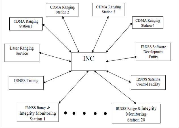
Fig 1.1: Architecture of INC
A Simulator has to be built which keeps track of IRIMS and IRCDR stations. The simulator has to detect the fault in
IJSER © 2012 http://www.ijser.org
International Journal of Scientific & Engineering Research, Volume 3, Issue 11, November-2012 4
ISSN 2229-5518
the stations and an alarm has to be raised. It should be flexible enough to drill down to particular equipment from
where the fault has been detected. The fault has to be corrected without affecting the operations of other stations. All the stations should be shown graphically and should be flexible enough to add or delete stations.
II. SYSTEM DESIGN
This paper aims at designing a simulator which helps in monitoring and controlling the system at INC (IRNSS Navigation Center). The simulator visualizes the working of various ground segment elements. This simulator covers the following operational scenario in a typical INC of IRNSS:
1: Operations and status monitoring of all station equipments of IRIMS( IRNSS Ranging and Integrity Monitoring
System) from INC.. analysis.
2: It displays the interconnections of all the equipments in each station.
3: Values of various parameters within the equipments are displayed for
4: Erroneous parameters are displayed in the error log.
5: The erroneous parameters are corrected to the default values.
This is done by reading the XML file[2],[3] from the disk and comparing the various station equipment’s parameters and displaying the respective status.
This section gives an explanation about the design of the system. The layered architecture is used to accomplish the
task.
IJSER © 2012 http://www.ijser.org
International Journal of Scientific & Engineering Research, Volume 3, Issue 11, November-2012 5
ISSN 2229-5518

Fig 2.1: Layered Architecture
III.SYSTEM DESIGN FOR FUNCTIONAL REQUIREMENTS:
Input File:
As shown in the above diagram, a XML file is read, where the required parameters are kept under different tags and these values are sent to the first layer Input Layer.
Input Layer:
This layer is basically used to collect the data from the XML file and pass it on the layer below that is Comparison and Processing
Comparison and Processing:
IJSER © 2012 http://www.ijser.org
International Journal of Scientific & Engineering Research, Volume 3, Issue 11, November-2012 6
ISSN 2229-5518
This layer is the heart of the project, as the data collected from the layer above is compared with the standard
XML file and id there is any error in the value suitable status is sent to the next layer.
Display:
This layer is responsible for displaying the various status of the stations and their equipments.
System design for non functional requirements:
System Design for Non Functional Requirements is an important part of overall design. The User Interface or the GUI[6] is one of the most important parts of a software product. This is mainly because the product being developed must be usable by any type of user with basic knowledge. The user’s job must be made very simple. The user must be able to access complex algorithms and functions at the touch of a button. These non functional requirements are not necessary for the basic functioning of the system but these are guidelines to make the product work well and be user friendly.
IV. DETAILED DESIGN Input Layer:
This layer consists of 2 modules.
1: Read module: This module is used to read data from the XML files.
2: Schedule module: This module is used to schedule the IRCDR stations. The IRCDR
stations are randomly picked for scheduling.
3: Module to create and delete stations: In this module, whenever a new configuration file is created, it will result in creation of IRCDR or IRIMS station based on the configuration file.
Processing and Comparison:
This module is used to read the data from the XML files and is checked against the standard range of values.
Display:
The status information will be received from the above layer and appropriate status info will be displayed.
IJSER © 2012 http://www.ijser.org
International Journal of Scientific & Engineering Research, Volume 3, Issue 11, November-2012 7
ISSN 2229-5518
User Interface[7]:
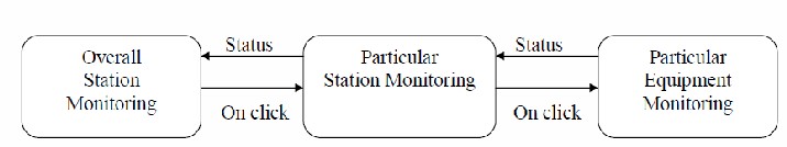
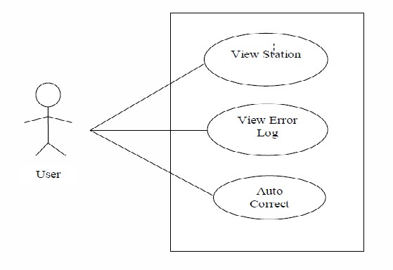
Fig 4.1: User interface
Fig 4.2: Use Case Diagram
IJSER © 2012 http://www.ijser.org
International Journal of Scientific & Engineering Research, Volume 3, Issue 11, November-2012 8
ISSN 2229-5518
User Reader Module File S)rstem
I I I I I I I
I, I
I I I I I
,...
{Verify File Type}
I I I I
I
- I
IJSER ©2012 http://www.qserorq
International Journal of Scientific & Engineering Research, Volume 3, Issue 11, November-2012 9
ISSN 2229-5518
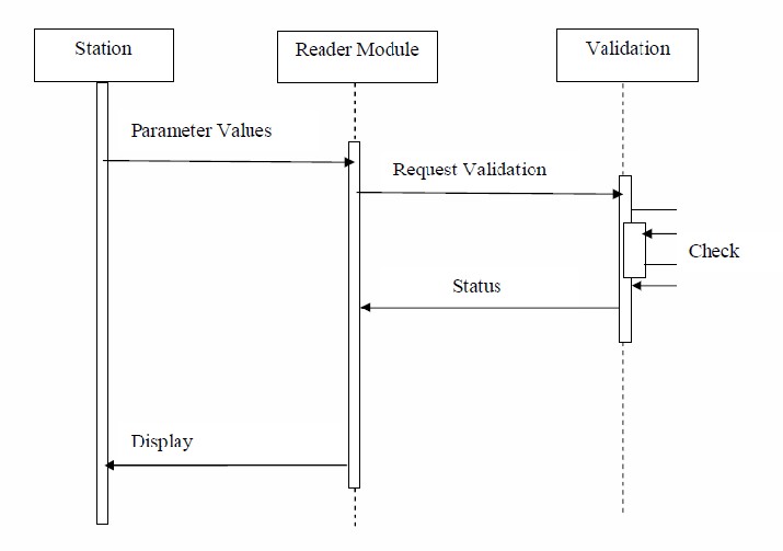
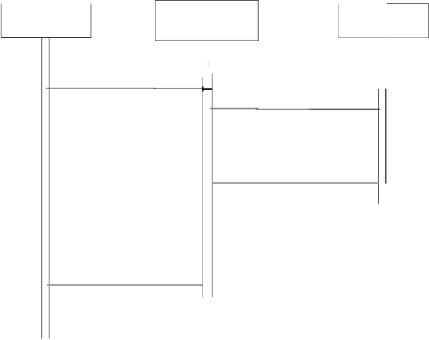
Fig 4.3: Sequence diagram for reader module
IJSER © 2012 http://www.ijser.org
International Journal of Scientific & Engineering Research, Volume 3, Issue 11, November-2012 10
ISSN 2229-5518
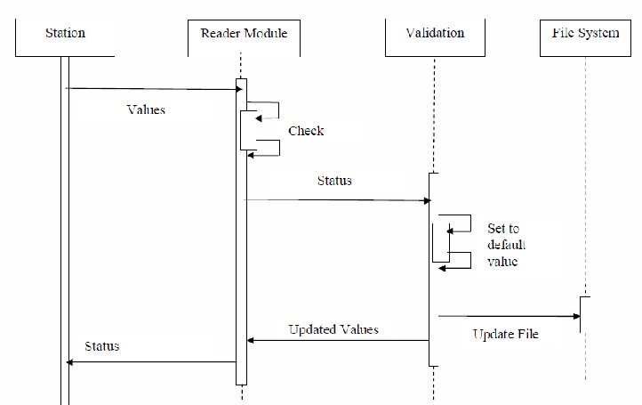
Fig 4.4: Sequence diagram for validation module
IJSER © 2012 http://www.ijser.org
International Journal of Scientific & Engineering Research, Volume 3, Issue 11, November-2012 11
ISSN 2229-5518
![]()
r·-·-·-·-·-·-·-·-·-·-·-·-·-·-·-·-·-·-·-·-·-·-·-·-·-· -·-· -·-·-·-·-·-·-1
. .
Model
ContTol Station factory ImpI
initO CreateO
Create IRNSS() Createstation( ) Create Equipment() CreatPayment
Parameter Impl
Name edefault :String Name:String Value:String
getName() setName() getVa lue( ) setValue()
Station Impl
Namedefault :String Name:String TYPE_DEFAULT:String Location:string
getName( )
IRNSS Impl
Namedefa ult :String Name:String Location_edefault:String Location:string
set ame() getName( ) getType( ) setame() setTypeO getLocation( ) getEquipments( ) setlocation( ) getLocation( ) getStation( )
! setLocation( ) getReference Station( ) !
L·-·-·-·-·-·-·-·-·-·-·-·-·-·-·-·-·-·-·-·-·-·-·-· -·-·-·-·-·-·-·-·-·-·-1
Fig 4.5: Class diagram
IJSER © 2012 http://www.qserorq
International Journal of Scientific & Engineering Research, Volume 3, Issue 11, November-2012 12
ISSN 2229-5518
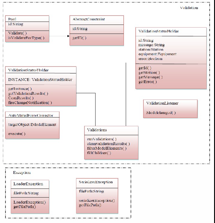
Fig 4.6: Class diagram
V. TESTING
IJSER © 2012 http://www.ijser.org
International Journal of Scientific & Engineering Research, Volume 3, Issue 11, November-2012 13
ISSN 2229-5518
Testing is part of Verification & Validation. Testing performs a very critical role for quality assurance and for
ensuring the reliability of the software.
During testing, the program to be tested is executed with a set of test cases, and the output of program for the test cases is evaluated to determine if the program is performing as it is expected to. Test cases are based primarily on the software requirements and developed to verify correct functionality and to establish conditions that reveal potential errors. Three levels of testing were carried out:
Unit Testing:
In computer programming[6],[7], unit testing is a software verification and validation method in which a programmer tests if individual units of source code are fit for use. A unit is the smallest testable part of an application. In procedural programming a unit may be an individual function or procedure.
Ideally, each test case is independent from the others: substitutes like method stubs, mock objects, fakes and test harnesses can be used to assist testing a module in isolation. Unit tests are typically written and run by software developers to ensure that code meets its design and behaves as intended. Its implementation can vary from being
very manual to being formalized as part of build automation.
Sl. No | Test sample | Expected result | Observed result | Test result Pass/Fail |
1 | Check for correctness of individual station | Status of station(Error/Healthy) | Station’s status(Error/Healthy) | Pass |
2 | Addition of Equipments | Equipments should be added | Equipments added | Pass |
3 | Addition of Parameters to Equipments | Parameters should be added to equipments | Parameters added | Pass |
4 | Autocorrect erroneous station | Station should be rectified | Station rectified | Pass |
5 | Delete Equipments | Equipments should be deleted | Equipments deleted | Pass |
6 | Delete Parameters From equipments | Parameters should be deleted | Parameters deleted | Pass |
IJSER © 2012 http://www.ijser.org
International Journal of Scientific & Engineering Research, Volume 3, Issue 11, November-2012 14
ISSN 2229-5518
7 | Add one or more level of hierarchy to the file | Hierarchy should be added | Hierarchy cannot be modified | Fail |
Table 1 Unit Testing
Integration Testing:
Integration testing is the phase in software testing in which individual software modules are combined and tested as a group. It occurs after unit testing and before system testing. Integration testing takes as its input modules that have been unit tested, groups them in larger aggregates, applies tests defined in an integration
test plan to those aggregates, and delivers as its output the integrated system ready for system testing.
Sl. No | Test sample | Expected result | Observed result | Test result Pass/Fail |
1 | Add Equipments to two or more stations | Equipments should be added | Equipments added | Pass |
2 | Add Parameters to Equipments to two or more stations | Parameters should be added | Parameters added | Pass |
3 | Autocorrect two or more stations | All stations should be rectified | All stations are rectified | Pass |
4 | Add stations to the model | Station should be added without affecting other stations | Stations are added | Pass |
Table 2 Integration Testing
System Testing:
System testing of software or hardware is testing conducted on a complete, integrated system to evaluate the system's compliance with its specified requirements. System testing falls within the scope of black
box testing, and as such, should require no knowledge of the inner design of the code or logic. As a rule, system
IJSER © 2012 http://www.ijser.org
International Journal of Scientific & Engineering Research, Volume 3, Issue 11, November-2012 15
ISSN 2229-5518
testing takes, as its input, all of the "integrated" software components that have successfully passed
integration testing and also the software system itself integrated with any applicable hardware system. The purpose of integration testing is to detect any inconsistencies between the software units that are integrated together or between any of the assemblages and the hardware. System testing is a more limit ing type of testing; it
seeks to detect defects both within the "inter-assemblages" and also within the system as a whole.
Sl. No | Test sample | Expected result | Observed result | Test result Pass/Fail |
1 | Check whether stations are independent of each other | Stations should be independent | Stations are independent | Pass |
2 | Check whether simultaneous inputs can be given to all the stations | Stations should accept the inputs | Stations accept inputs | Pass |
Table 3 System Testing
VI. ANNEXURE SCREENSHOTS
IJSER © 2012 http://www.ijser.org
International Journal of Scientific & Engineering Research, Volume 3, Issue 11, November-2012 16
ISSN 2229-5518
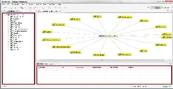
Fig 6.1: Main Window
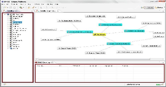
Fig 6.2: Station Window

Fig 6.3: Equipment Connection
IJSER © 2012 http://www.ijser.org
International Journal of Scientific & Engineering Research, Volume 3, Issue 11, November-2012 17
ISSN 2229-5518
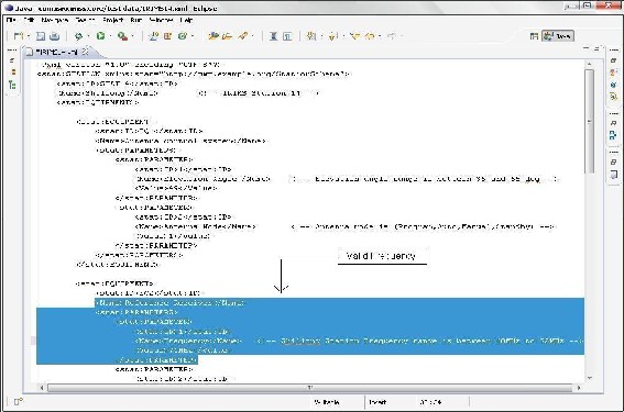
Fig 6.4: Valid XML File
IJSER © 2012 http://www.ijser.org
International Journal of Scientific & Engineering Research, Volume 3, Issue 11, November-2012 18
ISSN 2229-5518
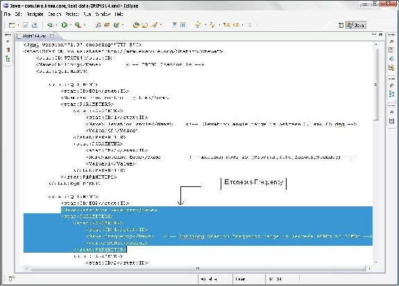
Fig 6.5: Erroneous Values
IJSER © 2012 http://www.ijser.org
International Journal of Scientific & Engineering Research, Volume 3, Issue 11, November-2012 19
ISSN 2229-5518
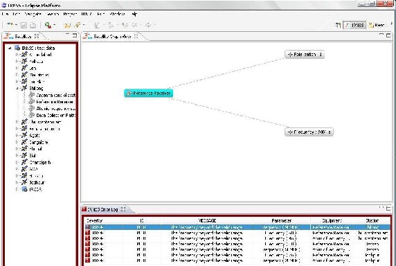
Fig 6.6: Error Log Showing Errors
IJSER © 2012 http://www.ijser.org
International Journal of Scientific & Engineering Research, Volume 3, Issue 11, November-2012 20
ISSN 2229-5518
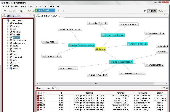
Fig 6.7: Auto Correct
IJSER © 2012 http://www.ijser.org
International Journal of Scientific & Engineering Research, Volume 3, Issue 11, November-2012 21
ISSN 2229-5518
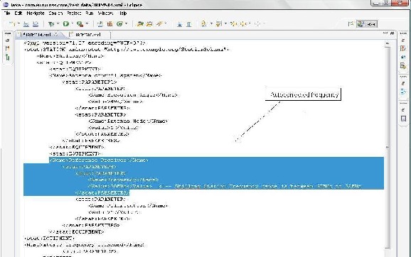
Fig 6.8: Auto Corrected XML File
IJSER © 2012 http://www.ijser.org
International Journal of Scientific & Engineering Research, Volume 3, Issue 11, November-2012 22
ISSN 2229-5518

Fig 6.9: Preferences
VII. CONCLUSIONS AND FUTURE ENHANCEMENTS
The simulator could simulate the behavior of both IRIMS and IRCDR stations. All the stations equipments and parameters could be monitored and could be displayed graphically. Any erroneous stations can be identified along with faulty equipments, which can be useful for rectification. Any addit ional station, along with the equipments and parameters can be added dynamically without affecting other stations. The simulator is extremely useful for monitoring the data acquired from the satellites and is platform independent.
The simulator can be extended to handle inputs using TCP/IP protocol. It can be enhanced to handle data of various formats. The simulator can be enhanced to perform other operations such as ranging and calibrations.
VIII. REFERENCES
[1] Indian Regional Navigational Satellite System(IRNSS) from ISRO.
IJSER © 2012 http://www.ijser.org
International Journal of Scientific & Engineering Research, Volume 3, Issue 11, November-2012 23
ISSN 2229-5518
[2] The Complete Reference Java, Herbert Schildt
[3] Thinking in Java - Bruce Eckel's
[4] http://www.isro.org/
[5] http://en.wikipedia.org/wiki/Indian_Space_Research_Organisation
[6] http://java.sun.com/
[7] http://www.java-forums.org/
IJSER © 2012 http://www.ijser.org
International Journal of Scientific & Engineering Research, Volume 3, Issue 11, N ovember-2012
ISSN 2229-5518
IJSER ©2012 http://www.qserorq