The research paper published by IJSER journal is about A Simulation Based Evaluation of Different Compressors For Fast Multiplication 1
ISSN 2229-5518
A Simulation Based Evaluation of Different
Compressors For Fast Multiplication
Nilay Nagdeve, Vishal Moyal, Ms. Archana Fande
Abstract— In this paper, a comparison between different compressors is presented. A proper compressor selection approach to get minimum XOR delay is also shown. Again Booth’s Modified Algorithm can be use for signed multiplication to get reduced partial products after which these compressors or a network of compressors can be used. This paper will help to choose a proper compressor for higher multiplication.
Index Terms— Compressor; Analysis; Multiplier; Modified Booth’s; adders; fast; performance
—————————— ——————————
1 INTRODUCTION
n adition is one of the basic process in maximum opera- tions. Also the various adders are available for large ad-
dition. But the result is not considered till all the bits have not been calculated, specially the MSB bits. Fortunately we have some fast adders which calculate the result in re- duced time than the normal. Compressors are one of the ways to calculate/Reduce the partial products of multiplication dur- ing an addition process. We have many of the compressors available to calculate. We will here compare the optimized compressors amongst all. Currently, TDM multiplier is one of the faster ways of multiplication.
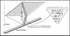
Fig. 1. Generation of partial product reduction tree in TDM multiplier
(Assady, 2009)
2 COMPRESSORS
2.1 Need of Compressors
The conventional adders are the chain of Full adders which generates carries and sum at each level. There was a delay while generating the Final MSB bits of result. During multipli- cation, Booth’s Algorithm or any conventional/Modified ap- proach can be used. But during the partial product addition, the conventional adders are not enough to reach the time con- straints. The normal adder structure for n bit addition is shown in figure 2 which adds two numbers with n number of bits but the output is not valid till the last MSB bit not appears. The carry travels through the adder to adder. This generates a delay which is consuming for carry propogation and altimate- ly efficiency of total circuit gets decreases.
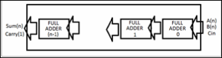
Fig. 2. Conventional Adder structure for n bit addition generating n bit sum and 1 bit carry
During the large operations like large multiplications for DSP applications, large chain of Full adders and half adders will need while following the large chain will lead to generate the larger and larger delays.
2.2 3:2 compressor
3:2 compressors are internally used shown in figure 3, for the ternary add capability. The two 3-LUT implementation can be merged easily with surrounding logic. There are enough spare inputs to absorb the AND gates associated with the first stage of a multiplier. Programmable negation XOR gates are another likely application.
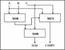
Fig.3. Basic structure of 3:2 compressor incudes 2 XORs and 1 Mux. (KWON, NOWKA, & EARL E. SWARTZLANDER, 2002)
2.3 4:2 Compressor
The higher compression rate is having by 4:2 compressors
IJSER © 2012
http://www.ijser.org
The research paper published by IJSER journal is about A Simulation Based Evaluation of Different Compressors For Fast Multiplication 2
ISSN 2229-5518
than 3:2 and shown in figure 4. The further work in improving the speed of a multiplier by optimizing Partial Product Reduc- tion Tree (PPRT) was extended by Oklobdzija, Villeger and Liu. Their approach was to optimize the entire PPRT in one pass, thus the name Three Dimensional optimization Method (TDM) shown in figure 1. The very main portion of this me- thod is hidden in sorting of fast inputs and producing fast outputs. It was realized that the most important step is to properly interconnect the elements used in the PPRT. Thus, appropriate counters (3:2 compressors in a particular case) were characterized in a way which identifies delay of each input to each output. Interconnecting of the PPRT was done in a way in which signals with large delays are connected to "fast inputs" and signals with small delay to "slow inputs" in a way that minimizes the critical paths in the PPRT. (Pallavi Devi Gopineedi, 2012)
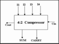
Fig. 4 4:2 compressor general structure
The 4:2 compressor structures actually compress five partial products bits into three [1, 2, and 3]. The architecture is con- nected in such a way that four of the inputs are coming from the same bit position of the weight j while one bit is fed from the neighboring position j-1(known as carry-in). The outputs of 4:2 compressor consists of one bit in the position j and two bits in the position j+1.This structure is called compressor since it compresses four partial products into two(while using one bit laterally connected between adjacent 4:2 compressors)
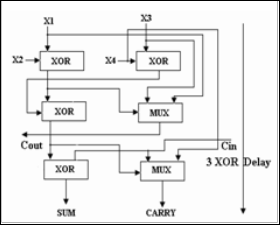
Fig.5. Alternative implementation of 4:2 compressor
Figure 4 shows the block diagram of 4-2 compressor. A 4-2 compressor can also be built using 3-2 compressors. It consists
of two 3-2 compressors (full adders) in series and involves a critical path of 4 XOR delays as shown in Figure 5. An alternative implementation is shown in Figure 5. This implementation is better and involves a critical path delay of three XOR's, hence reducing the critical path delay by 1 XOR. The output Cout, being independent of the input Cin accelerates the carry save summation of the partial products.
2.4 5:2 Compressor
The block diagram of a (5:2) compressor shown in Figure 6 has seven inputs and four outputs. Five of the inputs are the pri- mary inputs I1, I2, I3, I4 and I5 and two other inputs, Cinl and Cin2. The architecture is connected in such a way that five of the inputs come from the same bit position of the weight j while other two inputs (Cinl and Cin2) are fed from the neigh- boring position j-1(known as carry-in). The outputs of 5:2 compressor consists of one bit in the position j (sum) and two bits in the position j+1 (cout1, cout2, carry).
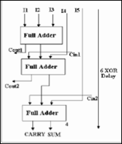
Fig.6. 5:2 Compressor general structure
A simple implementation of the (5, 2) compressor is to cascade three (3, 2) full adders in a hierarchical structure, as shown in Figure 6.
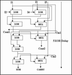
Fig.7. Alternative implementation of 5:2 compressor
This architecture has a critical path delay of 6 XOR gates. Figure 6 shows architecture of a (5:2) compressor. The
IJSER © 2012
http://www.ijser.org
The research paper published by IJSER journal is about A Simulation Based Evaluation of Different Compressors For Fast Multiplication 3
ISSN 2229-5518
implementation shows that this design has a critical path delay of 4XOR + 1MUX unlike the conventional implementation with a delay of 5XOR.
2.5 Higher compressors
The higher compressors like 6:2 and 9:2 compressors can also be made with the use of such 4:2 or 3:2 basic modules. The 5:2 compressor also can be made from the basic two.
3 SIMULATION MODEL
3.1 Compressor Structure
Here is the structure of 3:2 compressors which shows the application of 2 XOR delays. 3 inputs will reduce to Sum and carry. We can here use simple full adders. In a single adder there is a single XOR delay so combination may generate two or more XOR delays.
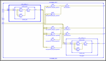
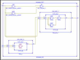
Fig.10. 5:2 RTL Schematic in Xilinx 12
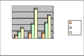
4 SIMULATION FITTING ANALYSIS
25
20
15
10
5
0
Microcells Pterms Used Functinal
3 To 2
4 To 2
5 To 2
Used
Blcok Input
Used
Fig.8. 3:2 RTL Schematic in Xilinx 12
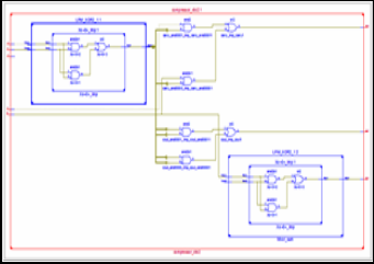
Fig.9. 4:2 RTL Schematic in Xilinx 12
Graph.1. Compressors comparision for area acquisition
Targeted device (xc9572-pc84)
Total Micro- cells Used MCHP+MCLP | 3 : 2 | 4 : 2 | 5 : 2 |
Total Micro- cells Used MCHP+MCLP | 2% | 5% | 8% |
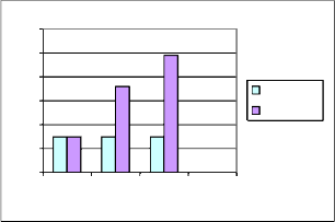
6 TIMING ANALYSIS
From the figures shown in graph 2, the minimum delay for all the 3 compressors are about same. This is the delay that the compressor having in 2 pads for which it requires least time. The maximum delay from graph 2 shows gradual increment. Ofcourse, when the size increses it affects the speed, but here the increment is not that much with respect to different com- pression rates. So higher is the compression rate may lead to higher delay but in exponential increment.
IJSER © 2012
http://www.ijser.org
The research paper published by IJSER journal is about A Simulation Based Evaluation of Different Compressors For Fast Multiplication 4
ISSN 2229-5518
30
25
20
15
10
5
0
3 To 2 4 To 2 5 To 2
Min Delay
Max Delay
Graph.2. Compressors comparision for timing delays (pad to pad) Targeted device (xc9572-pc84)
7 CONCLUSION
Different Counter and Compressor Families were compared. When the size compressor increses, the maximum delay asso- ciated with 2 pads will be higher than lower compressors but not greater than the ratio of the delay in them. Increse in size will cause the delay to be increase exponentially. The best way is to build a compressor of the maximal size (i.e. the entire size of the multiplier).
8 REFERENCES
[1] A 16-Bit by 16-Bit MAC Design Using Fast 5:3 Compressor Cells. KWON, OHSANG, NOWKA, KEVIN and EARL E. SWARTZLANDER, JR. 2002. 2002, Journal of VLSI Signal Processing, pp. 77-89.
[2] A New Multiplication Algorithm Using High-Speed Counters. Assady, P. 2009. 2009, European Journal of Scientific Research, pp. 362-368.
[3] Pallavi Devi Gopineedi, Hamid R. Arabnia. 2012. Novel
and Efficient 4:2 and 5:2 Compressors with Minimum number of Transistors Designed for Low-Power Operations. Georgia : Athens, 2012.
[4] Low Power CMOS Pass Logic 4-2 Compressor for High-Speed
Multiplication. D. Radhakrishnan, A.P. Preethy, Singapore,
2000
[5] G.M. Blair, “Designing Low Power CMOS”, IEEE Electronics and
Communication Engineering Journal, vol. 6, pp. 229-236, 1994.
[6] Z. Wang, G. A. Jullien and W. C. Miller, “A new design
technique for column compression multipliers,” in trans.
Comput., vol. 44, pp. 962-970, Aug. 1995.
[7] K. Prasad and K. K. Parhi, “Low-power 4-2 and 5-2
compressors,” in proc.signals,systems and computers, vol. 1, pp. 129-133, Nov. 2001
IJSER © 2012
http://www.ijser.org