International Journal of Scientific & Engineering Research, Volume 3, Issue 11, November-2012 1
ISSN 2229-5518
A Secured Voice over Internet Protocol (VoIP) Setup Using MiniSipServer
Ogundile O.O 1, Lawal B.H1 and Osanaiye O.A2
Abstract - What an alternative. Most people argue that if something works well there is no sense in changing it. This is exactly what is happening with VoIP today. Voice over Internet Protocol usually called VoIP is the transmission of voice, video conferencing, data, faxes over an IP based network. VoIP technology has received much attention due to several emerging application in voice communication. This paper presents a tutorial on a basic way of deploying VoIP using miniSipServer on an existing Metropolitan Area Network (MAN). After which security solution is deployed on the network using Virtual Private Network (VPN) due to the high security risk posed by VoIP as compared to the Public Switch Telephony Network (PSTN).
Index Terms - Networks, VoIP Setup and calls, VoIP Security, Virtual Private Network, VoIP as an alternative to PSTN.
—————————— ——————————
1 Introduction
As voice communication fast occupies the centre
stage in research and development, VoIP technology has emerge as a potential means of voice communication that will completely replace the existing PSTN [1]. VoIP uses a common network for the transmission of both voice and signal, thus, provides several benefits such as internet conferencing rooms, personalized call transfer, instant messaging, and cheaper call rate. VoIP technology reduces the operational cost with easier IT management for combined network for voice and data, which gives it an edge over PSTN [2].

1 - Department of Physics and Telecommunication, Tai
Solarin University of Education, Nigeria.
2 - Department of Telecommunication Engineering, Federal University of Technology, Minna, Nigeria.
Despite the numerous advantages VoIP technology posses when compared to the legendary PSTN, it is subjected to high security risk because of the open nature of the internet [3]. VoIP users always overlook the security threat posed by this technology. VoIP like every other new IT services or technology has some underlying security risk and susceptibility connected to it which can affect the efficiency, functionality and confidentiality of any business or organization. This security risk is as a result of the VoIP architecture which is different from that of the traditional circuit switched based telephone. Therefore, this paper presents a step by step practical VoIP setup on an existing MAN and measures of securing the setup VoIP network using VPN due to the security challenges associated with VoIP technology.
The rest of this paper is structured as follows. Section 2 presents the VoIP network setup at different locations on the existing MAN. Section 3 analyses the VPN tunnel deployed as a security measure on the network to prevent potential attack. Section 4 critically summarizes and concludes the paper while suggesting some future work that could be done.
2 VoIP Setup
IJSER © 2012 http://www.ijser.org
International Journal of Scientific & Engineering Research, Volume 3, Issue 11, November-2012 2
ISSN 2229-5518
The VoIP setup was carried out in a telecommunication training and research centre based in Lagos State, Nigeria. This research centre has three branches connected wirelessly via a Metropolitan Area Network (MAN) - the MAN service adopted for this network is the internet. The research centre has an existing network connecting its three branches in Lagos State. This has been considered as the right IT infrastructure to deploy this VoIP solution.
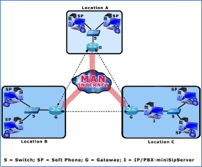
Figure 1: VoIP Setup across the Intranet.
Figure 1 presents the VoIP setup across the intranet of the research centre within the three locations - location A, B, and C. Voice traffic within each location does not require a gateway since the PCs are on the same network, but traffic to other locations will pass through a gateway for the purpose of resolving the name or phone number into an Internet Protocol (IP) address. Inter-site voice and data traffic shares the same network. In PSTN, the Private Branch Exchange (PBX) is used as the server to control the phones and other traffic on the network, but in VoIP the IP/PBX is used to control IP phones and softphones on remote sites, such that remote workers with IP access are enabled for voice calling. Traffic can also be routed to PSTN numbers through the gateway or gatekeeper by resolving the local telephone number into an IP address.
The following components are used in setting up the VoIP network:
Gateway
IP/PBX - MiniSipServer
Softphones
Gateway - Interconnects or allows communications among devices that are not accessible within the IP network, e.g. call from or to analog phones. It converts the signals from the traditional telephony interfaces to VoIP. Its main function includes voice packetization, compression or decompression, call routing and control signaling [4].
IP/PBX - MiniSipServer - The IP/PBX is a telephone switching system usually situated within the enterprise; it functions include switching, controlling and processing calls between VoIP users on a local line while enabling users to share some certain number of external phone lines [5]. It can be used to switch calls between a VoIP and PSTN user just like the conventional PBX does. It also has an advantage of converging data and voice network which provides flexibility and reduced long-term operational and maintenance cost for an organization. The IP-PBX can either be hardware or software based devices. A software based IP/PBX called miniSipServer is used for this VoIP setup. Softphones - These are end user devices in form of software installed on a personal computer (PC) to initiate and terminate calls. They can also be installed on mobile devices and have the same base features as VoIP phones [6].
2.1 Intranet VoIP Configuration
In setting up the VoIP network to make internal
calls within the research centre network, the first step is to install the miniSipServer (this software can be downloaded or purchased online). Since there is an existing network in the research centre, with all PCs allocated IP addresses. The miniSipServer is installed on a PC (IP address-
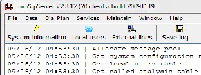
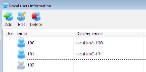
192.168.1.120) at location C which acts as the VoIP server for the MAN. After its installation the next thing is to make sure that the PC’s and the network are working well, therefore, the software is run on the PC (see figure 2). Immediately after installation, three default extension numbers are created. This can be viewed by clicking the local user icon on the main miniSipServer window. The default passwords for these extension numbers are 100, 101 and 102 (see figure 3). These default extension numbers cannot be edited but can be deleted or renamed - its display name can be changed.
IJSER © 2012 http://www.ijser.org
International Journal of Scientific & Engineering Research, Volume 3, Issue 11, November-2012 3
ISSN 2229-5518
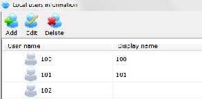
Figure 2: MiniSipServer Interface.
Figure 3: Extension Numbers.
After creating the VoIP server for the WAN, The client soft phones at all three locations can now be configured to connect to the server. Firstly, extension numbers or user IDs only (since all the PCs already have IP addresses) is allocated to all the PCs on the WAN. Softphones are then installed on the PCs on the MAN. The 3cx phone is the softphone used for this research work (Download- www.3cx.com). Let assume we were to install the
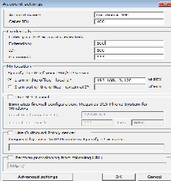
3cx phone on a PC (IP address-192.168.2.110 with extension number 100) at location A. After installation, we click >>> Account settings, then edit account (see figure 4). In the pop-up window, a Session Initiation Protocol (SIP) [7, 8, references therein] account is added.
Figure 4: Account Setting.
Table 1 describes the important entries used in completing the 3cx phone configuration.
Table 1: Setting Description.
After inputting these entries, the ‘OK’ button is clicked to complete the configuration. The 3cx phone will register with the miniSipServer. If it is successful, it reads configuration data and display information that it has connected. Similar procedure is also used to connect a PC (IP address-
192.168.3.116 with extension number 101) at location C to the miniSipServer.
The miniSipServer’ local user information status should be checked to confirm if the PCs are connected to the miniSipServer. Their icons display should be blue in colour (see figure 5) as against that of figure 3.
Figure 5: Checking Users Status.
A basic VoIP network has been established between a user at location A and location C. Therefore, the user in location A can dial ‘101’ to call the user in location C, and the user in location C can dial ‘100’ to call the user in location A.
The same procedure was used in connecting all the PCs on the MAN to the miniSipServer including the PCs in the same location as the server. However, new extension numbers were first added to the miniSipServer to accommodate all the PCs (see figure 6).
IJSER © 2012 http://www.ijser.org
International Journal of Scientific & Engineering Research, Volume 3, Issue 11, November-2012 4
ISSN 2229-5518
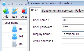

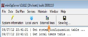
Figure 6: Adding New Extensions.
2.2 Extranet VoIP Configuration
As shown, it is so easy to establish internal VoIP

network for users at all locations (A, B, and C) of the research centre to enjoy. However, to establish external calls or to connect to the PSTN, we need a VoIP provider. Therefore, we connect the miniSipServer to a VoIP provider (see figure 7).
Figure 8: External Line Settings.
Table 2 describes the important entries used in adding the external line.
Item | Value |
External line | 08703920455 |
Password | Yes |
Peer server address | sip.sipgate.co.uk |
Peer server port | 5060 |
Automatic attendant | Yes |
Share outgoing calls with other local users | Yes |
Figure 7: VoIP Setup for External Calls.
Now that we have an SIP account-08703920455 from a VoIP provider, we can then configure the miniSipServer to connect to the VoIP provider. Firstly, we go back to the main miniSipServer window and then click the ‘External lines’ button to add external line information (see figure 8). In the pop up window, we click the ‘Add’ button to add an external line with VoIP provider’s account information.
Table 2: Settings for Adding External Line.
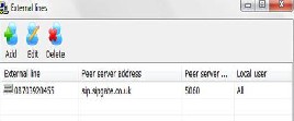
The miniSipServer’ local user information status should also be checked to confirm if the external lines can connect to the peer server (see figure 9).
Figure 9: Checking External Line Status.
2.2.1 Outgoing Calls
IJSER © 2012 http://www.ijser.org
International Journal of Scientific & Engineering Research, Volume 3, Issue 11, November-2012 5
ISSN 2229-5518
It has been established that all users can make internal calls by dialing individual extension numbers. Also, it is possible for users to make external calls, since the miniSipServer has been connected to a VoIP provider. However, to make outgoing calls a prefix ‘9’ will be added before we can dial the number. The prefix “9” is the default out-group prefix which is used to distinguish call type in miniSipServer. In this regard, if we want to call an external number -07045060004, you will add the default miniSipServer prefix - 907045060004
2.2.2 Incoming Calls
During the external line configuration automatic
attendant is activated so that when a call comes in, miniSipServer will prompt the caller to enter an extension number of the person he wants to talk to. For example, if a customer calls ‘08703920455’ (the external line provided by VoIP provider), the caller will hear ‘Welcome, please enter extension number’, the person can then enter 100 to call the user in location A or enter 101 to call the user in location C, or any other user on the network. This default announcement can be modified to suit the research centre’s real requirement.
3 VoIP Security Implementation
We have successfully setup a VoIP network across
the three branches of the research centre. However, it is incomplete if there is no safe passage of traffic on this network because there are now two valuable assets to protect - Voice and Data. Therefore, we need to ensure there is adequate security for this network. The problem of security would not have been much of a concern if the service adopted is the leased line - the lease line ensures confidentiality, integrity and availability which are now the three major attributes to be attained to establish a secured network. But using a leased line is very expensive. So the service adopted in this study is the internet which is a porous environment, and can encounter different security threats such as Man-in-the-middle Attack, Denial of service, IP-spoofing, masquerading, replay attacks [9, 10, references therein], which may affect the confidentiality, integrity, and availability of a user on this network.
VPN solution was deployed on the network to solve these issues arising from the aforementioned security threats and many more. Virtual Private Network is a private network that uses a public network to connect remote sites and users together and establishes its security on the network. It is the extension of a private network to allow links across shared or public networks like the internet. It permits traffic to be sent across a public or shared network in a mode that mimics the properties of a private network.
VPN is termed private because it ensures privacy and integrity on traffic that traverse the organization internetwork and the internet. It ensures this through the following:
Authentication
Encryption
Encapsulation
Authentication: The identity of a VPN client must be confirmed before gaining access to the network. Unregistered person will not be allowed on the network, and it also keep record and audit to show those who connected to the network and for how long.
Encryption: Traffic through the network would be meaningless to anyone who tries to interrupt it. It may be in the form of different letters of different languages and symbols. The encrypted traffic can only be deciphered by someone with the appropriate key and knowledge. Encryption ensures data integrity on the network, because it would become difficult for any person to modify the transmitted data.
Encapsulation: This is the process of enveloping the traffic as it pass across the network. An encapsulated data cannot be seen by an intruder, unlike encryption which renders the data jumbled. Encapsulation ensures confidentiality of clients on a network.
The bandwidth of the VoIP network should be the first issue to be considered when implementing security over VoIP network. Implementing security over VoIP network comes with a price. The encryption and decryption process that occurs during call transmission over the VPN tunnel (see figure 10) increases the overhead of the network
IJSER © 2012 http://www.ijser.org
International Journal of Scientific & Engineering Research, Volume 3, Issue 11, November-2012 6
ISSN 2229-5518
which in turn affects the bandwidth. VPN consumes additional bandwidth and lowers the call capacity when compared to the original transmitted voice packets before implementing it. If this issue is not properly addressed, it can affect the speech quality and the estimated Mean Opinion Score (MOS) which can leads to delay or latency.
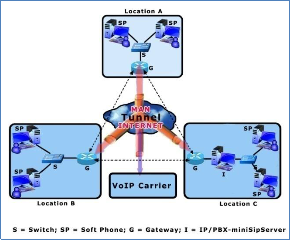
Figure 10: Example of VPN Tunnel.
VPN establishes security using what is referred to as Tunneling Protocol. Tunneling is the process of encapsulating packets within other packets to protect their integrity and privacy during transit [11]. A tunnel performs such tasks as encryption, authentication, packet forwarding, and masking of IP private addresses. Tunneling is a method whereby an internetwork infrastructure is used to transfer data from one network over another network [12]. Protocols enable the settings of authentication, encryption and encapsulation on the VPN.
Since we aim at establishing security on an intranet, a site-to-site VPN will be deployed. Therefore, protocol (Internet Protocol Security - IPSec) for site-to-site VPN is established at layer three (Network layer) of the Open System Interconnection (OSI) model - that is, the VPN solution is deployed on the router (gateway).
Internet Protocol Security (IPSec) is used to send secured traffic over a public network. It allows packets to be authenticated, encrypted and encapsulated before being transmitted across the network. In addition, it negotiates by checking the configuration among the gateways, it ensures that
the same key is used for all the gateways, if there is any difference during negotiation, the network will fail to establish. IPSec is used only at the network layer since it is a site-to-site VPN protocol. It ensures authentication between clients and also protects traffic flow between security gateways - that is, network-to-network or between a gateway and a host [13].
The table below explains the protocols employed in using IPSec over the VoIP network setup.
Table 3: IPSec Protocol Key
Though, negotiation came last in table 4, but it is usually the first security measure because the three routers have to negotiate before the network could be established, this implies that same keys is used when configuring the authentication, encryption and encapsulation keys. For example, if MD5 is used as the authentication key for the VPN router in location B, MD5 must also be used as the authentication key for the VPN router at other locations, otherwise, the network connection will not be established. For security reasons, the keys used will not be mentioned.
MD5 or SHA1 is the key used for authenticating in IPSec. It authorizes eligible members on the network and protect against unregistered person. We have to know that it ensures network availability since it will only allow registered members on the network which will in turn manage the available bandwidth. Its function in protecting the network is limited because it cannot protect against a registered member on the network who wants to infringe its security.
DES, 3DES, or AES are the keys that can be used for encrypting traffic as it passes through the network. What this key does is to encrypt the traffic to be transported into something meaningless so that if a sniper gets into the network such person will be unable to interpret the message let alone
IJSER © 2012 http://www.ijser.org
International Journal of Scientific & Engineering Research, Volume 3, Issue 11, November-2012 7
ISSN 2229-5518
modifying it, therefore, we have ensure integrity on the VoIP network - that is, what the sender intends is properly delivered at the receiving end.
AH or ESP is the key used to create a tunnel in the network in which any traffic transported through it will be safe. This is the most important aspect of IPSec that makes it an essential security tool because the key encapsulates the header or both the header and data of the payload depending on the key type, and placing it in a new IP Packet. The only information that can be seen is the IPSec header and the new IP Header for the encapsulating packet.
Since our network is established through a
gateway, a tunnel will be created between the gateways. The IP addresses of the gateways are used as the unencrypted IP address. If an intruder intercepts these packets, he would be unable to determine the packet contents as well as its origin and destination. Though, traffic analysis is possible to some extent in tunneling, because the gateway addresses are readable. An attacker can resolve the identity of the communicating organizations from the gateway addresses. The identity of this organizations can only be determined if the gateway is used exclusively by the organization, but IPSec does one more thing which is negotiating the security policy which defines the security protocol - that is, defining the authentication key, encryption algorithm key, and encapsulation key to be used. Though the addresses might be known but the attacker will be unable to join or tamper with the network, or know the content being transported.
Note that in securing the VoIP network, we aim
at securing the entire MAN such that any message (voice or data) that passes through the network is secured. Also, the key type choice for authentication, encryption and encapsulation depends on the need or priority of the user. However, users must ensure the same configuration settings among the gateways, and the bandwidth of the network must be taken into consideration to avoid delay or latency in the network. Few seconds delay in data transmission may be accepted, but similar delay will render VoIP useless and unacceptable to it users.
4 Summary and Conclusion
This paper has demonstrated how to deploy VoIP
solution across a Metropolitan Area Network using miniSipServer. It has been shown that VoIP provides favourable environment, as it does not require much infrastructure as compared to the legendary PSTN, all it requires is a working network which is already in existence - Internet. We only need to integrate our voice call on this network. However, the security threats associated with the internet has been a setback for the integration of VoIP into this global network.
Also, we have demonstrated in this paper a suitable way of securing a VoIP network using VPN. But, there is a trade-off between the quality of service and this security implementation because of the amount of bandwidth consumed while the network is undergoing this security check. If VoIP could ensure maximum security on the confidentiality, integrity, and availability of the voice traffic passing through the network, then, there is reason for making VoIP an alternative to the PSTN.
Acknowledgement
The authors acknowledge TTC mobile Lagos,
Nigeria, an IT based research and training centre, for their support in carrying out this research work.
References
[1] S. Ansari and A. Khan (2007), ‘Voice over
Internet Protocol Security problems in wireless
Environment,’ Journal of Engineering and Science,
1(2), pp. 82-85.
[2] M. Ranganathan and L. Kilimartin (2003),
‘Performance analysis of secure session initiation protocol based VoIP networks,’ Computer Communications 26(6), pp.552-565.
[3] E. Amoroso (1994), ‘A book introducing critical issues in computer security technology,’ Fundamentals of Computer Security Technology, Bell Laboratories.
[4] R. Dhamankar (2005), ‘Intrusion Prevention: The Future of VoIP Security,’ White paper by Tripping Point.
IJSER © 2012 http://www.ijser.org
International Journal of Scientific & Engineering Research, Volume 3, Issue 11, November-2012 8
ISSN 2229-5518
[5] Ramachandran (2006), VoIP Security: asserting the trust boundary, ‘The Global Voice of Information Security,’ ISSA Journal pp.8-13.
[6] M. Desantis (2008), ‘Understanding Voice over
Internet Protocol (VoIP),’ US-CER.
[7] S. Karapantazis and F. Pavlidou (2009), ‘VoIP: A comprehensive survey on promising technology,
’Computer Networks, 53(12), pp.2050-2090.
[8] D. Geneiatakis, C. Lambrinoudakis and G. Kambourakis (2007), ‘An ontology - based policy for deploying secure SIP-based VoIP services,’ Computer & Security, 2006(27), pp.285-297.
[9] E. Fernandez, J. Palaez, and M. Larrondo-Petrie (2007), ‘Security Patterns for Voice over IP Networks,’ Journals of Software, 2(2), pp. 19-29. [10] D. Ramirez (2007), ‘Security within VoIP networks,’ Information Systems Control Journal, Vol 6.
[11] Cisco Networkers 2000, http://www.cisco.com/networkers/nw00/pres/2403. pdf Accessed date 21st of September, 2012.
[12] Microsoft Windows Server 2003 White Paper. [13] Kent, S. Atkinson, R. (November 1998). IP Encapsulating Security Payload (ESP). IETF. RFC
2406. Accessed date 21st of September, 2012.
IJSER © 2012 http://www.ijser.org