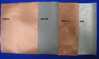
like. Flectron, Shieldit, Zelt and Pure Copper Polyester
Taffeta.
International Journal of Scientific & Engineering Research, Volume 4, Issue 12, December-2013 696
ISSN 2229-5518
A Review on Wearable – Textile Patch Antenna
Sweety Purohit,Falguni Raval
Abstract—W ireless communication technology increasing day by day because of rapid development of antenna. W earable antenna is mainly used in medical field, mobile communication, navigation and military. W earable antenna is device which used as man and machine interface device, which is part of smart clothing. Textile patch antenna used fabric material for substrate, patch and ground and it becomes part of wearable clothing.Fabric dielectric constant is low so it is used to reduce to surface wave losses and improve bandwidth.There is certain criteria for selection of fabric as substrate or patch and using different method it can fabricate.
Body-centric communications takes its place firmly within the sphere of personal area networks (PANs) and body area networks (BANs). One of the applications – the on-body communications – It is the link between bodies mounted devices communicating wirelessly, while off-body communication is the radio link between body worn devices and base units or mobile devices located in surrounding environment. Finally, in-body communication is communication between wireless medical implants and on body nodes [1]. Patch antenna has many advantages, like low weight, low profile, easy to fabricate, integrated into
like. Flectron, Shieldit, Zelt and Pure Copper Polyester
Taffeta.
Fig 1 Microstrip patch antenna
IJSER
microwave integrated circuits [2].
The limitations of conventional microstrip patch
antennas are more deposition of electromagnetic signals in
the human body that is high specific absorption rate (SAR)
though their physical size is large. Secondly, due to size it is
difficult to integrate and make them hidden inside the clothing of wearer [3-9]. Hence, a wearable antenna that is the textile based antenna is one of the better alternatives for such type of applications. The wearable antenna should be light weight, flexible, compact, and hidden and should be easily integrated within the clothing and it should not affect the health of wearer.
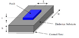
Micro strip patch antenna consists of a radiating patch on one side of a dielectric substrate which has a ground plane on the other side as shown in Fig. 1.The patch is generally made of conducting material such as copper or gold and can take any possible shape. The radiating patch and the feed lines are usually photo etched on the dielectric substrate.
Two types of partial wearable antenna are possible.In Partial wearable patch antenna substrate is dielectric material within range of 2 to 10 and either ground; patch should be conducting fabric material.
In fully wearable antenna substrate is fabric like jeans, polyster, cotton. And patch, ground are conducting fabric
The permittivity, ε that is a complex value parameter. It is also expressed as a relative value εr : ε = ε0 εr = ε0(ε’r− jε’’r), where ε0 is the permittivity of vacuum, which is 8.854 ×
10−12 F/m [2]. In general, the dielectric properties depend on the frequency, temperature, and surface roughness [2], and also on the moisture content, purity and homogeneity of the material. The real part of the relative permittivity, ε’r, is called the dielectric constant, but one must note that it is not constant in frequency.
For the design of patch antenna dielectric constant of substrate is in the range of 2.2 ≤ εr≤ 12. But for textile material dielectric constant is less than 2.
The lower dielectric constant reduces the surface wave losses which are tied to guided wave propagation within
the substrates. Therefore, lowering the dielectric constant increases spatial waves and hence increases the impedance bandwidth of the antenna, allowing the development of antennas with acceptable efficiency and high gain.
Loss tangent tanδ (also known as dissipation factor) characterizes the amount of power turned into heat in the material. It is given by the ratio of imaginary ε ′′ to the real part ε ′ of the permittivity: tan δ = ε ′′/ ε ′ The higher the loss tangent values the more loss the dielectric substrate. Higher losses mean reduced radiation efficiency.
IJSER © 2013 http://www.ijser.org
International Journal of Scientific & Engineering Research, Volume 4, Issue 12, December-2013 697
ISSN 2229-5518
The bandwidth and efficiency of a patch antenna is mainly decided by the substrate dielectric constant and its thickness. The thickness h of substrate is usually in the range of 0.003λ ≤ h ≤ 0.005λ where λ is a wavelength. For a fixed relative permittivity, the substrate thickness may be chosen to maximize the bandwidth of the patch antenna. However, this value may not optimize the antenna efficiency. Therefore, the choice of the thickness of the dielectric material is a compromise between efficiency and bandwidth of the antenna [4,31]. The influence of the thickness on the bandwidth (BW) of the antenna may be
explained by Equation (1), where Q is the antenna quality
factor
Fig 2 Sample of taffeta, shieldit, flectron ,zelt electro-textile material
1![]()
BW~
Q
(1)
For textile the extent to which a material is sensitive to
The Q factor is influenced by the space wave (Qrad) losses,
the conduction ohmic Qc ) losses, the surface waves (Qsw)
and dielectric (Qd) losses as shown in Equation (2) [4]:
moisture is described by its regain, which is defined, by the ratio of the mass of absorbed water in specimen to the mass of dry specimen, expressed as a percentage, [8]![]()
![]()
1 = 1
![]()
![]()
![]()
+ 1 + 1 + 1
(2)
Although this value depends on the salinity, temperature
Qt Qrad Qd Qc
Qsw
For thin substrates the quality factor associated with radiation (Qrad) is inversely proportional to the height of the substrate [4]. Therefore, increasing the height of the substrate lowers the Q factor (Qt). As the Q-factor decreases
and frequency [3], water has a much higher and more stable
dielectric constant than textile fabrics, whose dielectric
constant is generally in the range ε’r = 1 – 2 because of their
high porosity. Therefore, when water is absorbed by the
IJSER
with an increased aperture between the patch and the
ground planes of the antenna, a thicker substrate allows a larger antenna bandwidth [6]. Moreover, the thickness of the substrate also influences the geometric sizing of the antenna. This means that a thick substrate with low relative permittivity (value between 1 and 2) results in a large patch and a thin substrate with the same dielectric constant results in a smaller patch [5].
These fabrics must have a very low electrical surface resistance in order to minimize the electric losses and thus increase the antenna efficiency. Despite the fact that the surface resistance value should be constant over the area of the antenna [9], the fabric may present some heterogeneity, such as for instance some discontinuities in the electric current. If these discontinuities are parallel to the surface current they will not interfere with the electromagnetic fields [5], but if discontinuities impede the flow of the electrical current, the fabric resistance will increase [9].
textile fibres or is trapped into the fabric structure, it
changes the electromagnetic properties of the fabric,
increasing its dielectric constant and loss.[3]
A curvature on a human body consists of a superposition of bends in arbitrary directions. Because of their excel flexibility and elasticity textile materials adapt well to these surfaces. However, when the textile fabric adapts to the surface topology it bends and deforms, causing changes to its electromagnetic properties and its change the antenna performance .[3] Indeed, the bending and the elongation of the dielectric fabric influence its permittivity and its thickness, which affects the resonance frequency of the antenna and especially the bandwidth, as previously explained [3].
To design, a rectangular microstrip patch antenna which has the given fabric material as its substrate is to be designed assuming an approximate value of dielectric constant. The value of the dielectric constant of this fabric substrate material may be computed by simply measuring the resonant frequency of the patch radiator. The design of the microstrip patch antenna involves the calculation of its patch dimensions.
The patch width (W) has a minor effect on the resonant
frequency (fr), and it is calculated using the following
formula [5]
IJSER © 2013 http://www.ijser.org
International Journal of Scientific & Engineering Research, Volume 4, Issue 12, December-2013 698
ISSN 2229-5518
c![]()
w =
2fr
2![]()
�
(εr + 1)![]()
(3)
Where c is the speed of light in free space and εr is the
relative permittivity of the fabric material under test. The microstrip patch lies between air and the dielectric material, and thus, the EM wave sees an effective permittivity (εreff ) given by [5]
adhesives was impractical. As a result, the adhesive acts as insulator among the conductive yarns. Because of the uneven distribution, electrical resistance showed in homogeneity, and it could rise by a factor of ten at certain spots.
antennas patch and ground plane because the sewing
IJSEneedle pulledRsmall conductive fibers from the patch
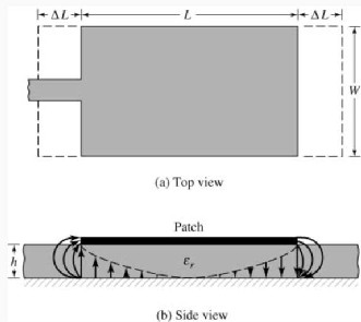
Fig 3 Physical and effective length of microstrip patch
through the substrate and shorted them with the ground
plane. Besides, sewing could not be used with the spacer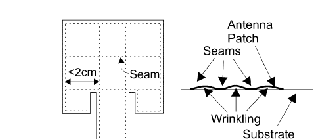
𝜀𝑟eff = �
![]()
![]()
𝜀𝑟 + 1
� + �
2
𝜀𝑟 − 1
2
� �1 +
12ℎ
𝑊
![]()
−1�2
�
(4)
fabric substrate since the high pressure of the sewing seam compressed the substrate permanently.
Where h is the thickness of the substrate.
The patch length (L) determines the resonant frequency and
It is a critical parameter in design because of the inherent narrow bandwidth of the patch The design value for L is given by [5]![]()
c
L = � � − 2∆L (5)
�2fr√ εreff�
Where εreff is the effective permittivity of the material
under
test. The additional line length on ΔL both ends of the patch
length, due to the effect of fringing fields, is given by [5]
Fig 4 Sewed antenna (a) sewed patch antenna with seam grid (b) Wrinkling of antenna between seams
![]()
ΔL
= 0.412 �
(εreff + 0.3)
w
� � h + 0.264�� (6)
deposits as a thin layer on the conductive textile by ironing.
Moreover, the adhesive only penetrates the surface of the
h (εreff − 0.258)![]()
![]()
�w + 0.8�
h
conductive textile such that patch sheet resistance and
substrate permittivity are not changed.
The effective patch length Le is written as
Le = L + 2∆L (7)
Hence, the knowledge of the actual (measured) resonant
frequency for extracting the value of εr of the fabric
For fabrication, the following four methods are used.
Besides that, a more flexible fabrication technique to use a
conductive spray technique, which can be applied to any
textile material [17]. The spray, which is a mixture of copper
with gases under pressure, can be used to obtain a
conductive layer on the textile surfaces exposed to the
spray. Figure 7 A SMA jack was connected to the textile antenna using conductive two component glue conducting part of the antenna copper tape, copper thread and conductive spray was used to see their affect on wearable antenna performance. In order to improve the bond
IJSER © 2013 http://www.ijser.org
International Journal of Scientific & Engineering Research, Volume 4, Issue 12, December-2013 699
ISSN 2229-5518
between the conducting layer and textile fabric a new assembly technique based on adhesive sheet and ironing was proposed [45] by designing a rectangular ring antenna using fleece fabric and electro textile. After choosing the textile materials to design an antenna, their assemblage in the antenna is also crucial and specific, as they are very deformable materials. Thus, the conformation of the conductive patch with the dielectric substrate is critical [2]. Many authors have been improving the manufacturing processes [2,5,24,27] to construct textile antennas and some guidelines can be summarized as follows:
1. The geometrical dimensions of the patch should remain stable while connecting to the dielectric substrate as the mechanical stabilization of both materials is essential to preserve the desired antenna characteristics
2 The techniques used to connect the various layers must not affect the electrical properties of the patch, such as its surface resistivity, nor the properties of the substrate. Connections using adhesive sheets or conductive fabrics with a thermal adhesive face have shown good results [2,5,29,31]. Indeed, the adhesive remains at the interface of the materials and therefore the surface resistance of the patch and the relative permittivity of the substrate are not
3 The positioning of the textile components must consider the differences between right and back faces, in terms of roughness and of density of conductive elements [7,10]. In [10], a satin 5 woven was tested in a microstrip resonator, placing it in two positions: (1) with the right face against the dielectric substrate and (2) with the back face, the conductive one, against the dielectric substrate. It was observed that when the conductive face is placed on the top of the substrate and so underneath the nonconductive yarns of the nonconductive face, most of the electrical field is contained in the substrate. Thus, the dielectric loss in the nonconductive yarns is minimized.
4 The core of the antenna may be obtained by stacking low- loss fabrics [7], adjusting this way the desired thickness of the substrate. However this introduces heterogeneities in the substrate due to the extra layers of air between the fabrics, influencing its dielectric properties.
5. Finally, the connections at the antenna terminals may also be critical as in wearable and flexible antennas these connections have to be mechanically robust. In general, textile fabrics cannot be directly soldered to (an exception is Flectron® that already showed good resistance to soldering [5]). Therefore conductive epoxy has been used, but some
IJSER
significantly changed. However, in [29] the authors Sensors
2012, 12 15852 show that the adhesive layer introduces extra
losses in the substrate. This process of attachment of the
superposed layers is very simple to perform by a simple
ironing operation. However, attention should be made to
the ironing process, in special if the patch is made of a fabric with metallic components. Indeed, the oxidation of the metallic component, due to the hot moistening of the fabric, may increase the surface resistance of the fabric and so decrease the efficiency of the textile antenna [27]. Connection with seams is an alternative technique [7,31] but it presents some difficulties. Firstly, the seam must be plane, without wrinkling, what might be difficult to achieve with deformable materials. Secondly, the stitch passes through all materials: the patch, then the substrate and further the ground plane of the antenna, which may cause electrical shorts between them. In Locher et al. [2] report that the sewing needle has pulled conductive fibers from the patch through the substrate, shorting the patch with the ground plane. Another technique is connecting with liquid adhesives [31]. However, it is difficult to apply a thin layer of glue. This difficulty introduces heterogeneity and in the zones where there are accumulations the glue may play the role of insulator between the conductive yarns of the patch. Furthermore, these adhesives are usually stiff and brittle, and so they cannot be applied in an area-wide manner on textiles as they will interfere in their flexibility [2]. In order to obtain a uniform thickness of the attachment of the several layers, Tronquo et al. [29,31] perform an additional stitch, in addition to the glue. In [5] a smooth fabric was added to both faces of the substrate to optimize the attachment of the conductive components.
concerns remain as this connection is not very resistant [44]
.
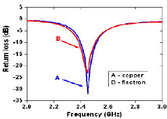
Fig 5 Return loss characteristic of circular W LAN antenna
IJSER © 2013 http://www.ijser.org
International Journal of Scientific & Engineering Research, Volume 4, Issue 12, December-2013 700
ISSN 2229-5518
The health parameters that may be transmitted wirelessly to remote stations (off body mode) in telemedicine systems.[10] In addition to off body applications, on body mode is also necessary for communication between sensors devices located on or within the patient's body[6].Therefore a reliable low profile antenna is required for best performance. Various types and design approaches of wearable antennas are being proposed including: Electro- textile, microstrip patches, buttons antennas, wearable MIMO systems, or hybrid systems based on one or more of such designs.Wearable antennas are required to be small size, lightweight, but robust at the same time.[10]They also have to be comfortable and conformal to the body shape, yet they must maintain high performance in terms of reliability and efficiency.[10]Electro textile based antennas seem to be a low profile low profile solution for wearable application; however, they are more prone to discontinuities in substrate material, fluids absorption, bending, twisting, and compression. The wearable antenna for telemedicine has proven to be better option for patient monitoring. [10]
In [2] textile patch antennas for Bluetooth in the frequency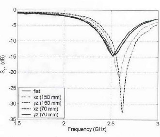
antennas' resonance length. The more the antenna is bent, i.e., around smaller diameter, the more resonance length is reduced, and thus it is shifted up. This is observable for both antennas. However, yz-plane bending affects on the resonance frequency of the conventional patch antenna as well.
Fig 6 Results of S11 for patch antenna under bending
range from 2400 to 2483.5IMHz. JOur antennaSs feature a 10- ER
dB bandwidth of 200 MHz on average. Even when bent
around a radius of 37.5 mm resembling a mounting on a
human upper arm, Bluetooth specifications can be assured. The planar structure with a maximal thickness of 6 mm maintains wearing comfort when integrated into clothing.
In wearable systems, flat antenna surfaces cannot be provided in general [3]. Therefore, antennas should properly function even if they are bent.
7.2.1 Return loss of Antenna
It can be observed that yz-plane bending has minor effect on antenna performance compared to xz-plane bending. This is due to the fact that xz-planebending affects on the
7.2.2 Radiation Pattern of Antenna The radiation
characteristics under bending conditions were measured in
an Anechoic Chamber. The standard AUT (antenna under
test) positioned setup in the chamber was modified for this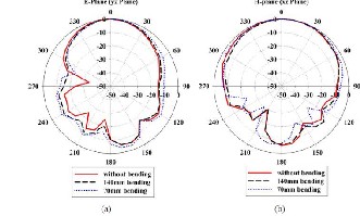
purpose.
Fig 7 Measured Radiation pattern for (a) E plane (b) H plane
The radiation patterns were measured for two orthogonal bending planes (E-plane and H-plane). The measured pattern cuts in E-plane and H-plane for these two bending positions on 140mm and 70mm foam cylinders are shown in Figure 6-6 and Figure 6-7 respectively. The patterns for the unbending case are also plotted to compare the variation in pattern shape. The results show that antenna bending has remarkable effect on radiation characteristics, i.e., radiation pattern shape and gain. It is intuitively clear that antenna
IJSER © 2013 http://www.ijser.org
International Journal of Scientific & Engineering Research, Volume 4, Issue 12, December-2013 701
ISSN 2229-5518
bending broadens the radiation pattern in the bending plane which results in a drop of gain. For bending on smaller 70mm diameter this effect is more obvious. For H- plane bending there was not much deviation in pattern shape in relation to the unbending case for both E-plane and H-plane cuts.
The antenna maintained its broadside radiation
performance under bending condition. Also the 3dB HPBW
in H-plane cut was broader as compared to E-plane as was the case without bending. The front-to-back ratio (F/B) in E- plane remained at 10dB while in H-plane it reduced to 8dB on 140mm cylinder and 6dB on 70mm cylinder. Also for H- plane cut under E-plane bending the radiation pattern seemed to be changing to omni directional which is not desirable for on body antennas. It can therefore be concluded that this antenna functions normally under bending condition in general. However, bending along E- plane should be avoided as it affects the directional characteristics of antenna.
7.3 Polarization of Antenna
Polarization of Antenna the resonant frequency changed when antenna was bent in the E-plane while H-plane bending has minimal effect on the resonant frequency.
Measurement setup for bending condition. (a) H-plane
Fabric antennas made of textile material contain voids that can easily absorb water and moisture and can consequently change the resonant frequency and impedance bandwidth of an antenna.[]
8 CONCLUSION .
From this paper we conclude that wearable antenna is useful for off body communication in personal area network. It use in medical application, military, sports. In future washable wearable antenna, with different textile material can be possible. To feed antennas commonly used metallic SMA connectors, microstrip feeding, coaxial probe feeding was employed. These connectors are large in size and heavy in weight especially for wearable applications. In future new types of connectors can be proposed that are small and light weight. And also different feeding tech. can be possible for future work. The SAR is potentially important to any wearable antenna as they are placed in very close proximity to the body. There is nonspecific legislation which considers wearable devices; however minimization of SAR is a sensible design goal. For this reason the SAR characteristics of wearable antennas
designed in this research could be carried as future work.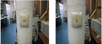
bending, (b) plane bendingI[3] JSER
I wish to thank Dr S.Sankaralingam who is Senior Member of IEEE .He help me to enhance fabrication and design criteria of wearable patch antenna.
Fig 8 Measurement setup for bending condition (a) E plane bending (b) H- plane bending
Public concern regarding the health effects of radiation and legal requirements around the world have urged engineers and researchers to always consider the amount of power absorbed by the human body. Therefore, specific absorption rate (SAR) by wireless devices has been defined. The two most commonly used SAR limit are those of IEEE [20]
1.6W/kg for any 1g of tissue, and ICNIRP (International
Commission on Non-Ionizing Radiation Protection [21])
2W/kg for any 10g of tissue. In [22], a torso model
constructed from CT and MRI image of real human body
was employed in the SAR modeling. The model was used to study the antenna performance when the antenna placed was on the upper portion of the human body. Figure 8 is an example of simulated SAR distribution at 2.2 GHz. From the simulated result, the SAR distribution was given for 1 Watt delivered power and the color bar showed relative SAR value in dBi.
10 REFERENCES
[1] Hall, P. S., and Hao, Y., “Antennas and Propagation for Body Centric Communications”, European Conference on Antennas and Propagation (EuCAP), November 2006
[2] Baker-Jarvis ; Janezic, M.D.; DeGroot, D.C. High-Frequency
Dielectric Measurements. IEEE Trans. Instrum. Meas. 2010, 13, 24–
31.
[3] Rita Salvado 1,*, Caroline Loss 1, Ricardo Gonçalves 2 and Pedro Pinho Textile Materials for the Design of Wearable Antennas: A Survey
[4] S.Sankaralingam and Bhaskar Gupta “A Circular Disk Microstrip
WLAN Antenna for Wearable Applications”
[5] Balanis, C.A. Antenna Theory: Analysis and Design, 3rd ed.; Wiley Interscience: Hoboken, NJ, USA, 2005.
[6] Hertleer, C.; Rogier, H.; Member, S.; Vallozzi, L.; Langenhove, L.V. A “Textile Antenna for Off-Body Communication Integrated into Protective Clothing for Firefighters”. IEEE Trans. Adv.Pack.
2009, 57, 919–925
[7] Sonia C. Survase,Vidya V.Deshmukh “Design of Wearable
Antenna for Telemedicine Applicatio”,IJESIT
[8] Morton, W.E.; Hearle, W.S. Physical Properties of Textile Fibres,
4th ed.; Woodhead Publishing: Cambridge, UK, 2008.
[9] Locher, I.; Klemm, M.; Kirstein, T.; Tröster, G. Design and Characterization of Purely Textile Patch Antennas. IEEE Trans. Adv. Pack. 2006, 29, 777–788.
IJSER © 2013 http://www.ijser.org
International Journal of Scientific & Engineering Research, Volume 4, Issue 12, December-2013
ISSN 2229-5518
702
[10] Wearable Yagi Microstrip Antenna for Telemedicine Applications Haider R. Khaleel*, Hussain M. Al-Rizzo, Daniel G. Rucker, and Taha A. Elwi Haider R. Khaleel*, Hussain M. Al-Rizzo, Daniel G. Rucker, and Taha A. Elwi University of Arkansas at Little Rock, Little Rock, AR 72204.
[11] Shahid Bashir Doctoral Thesis "Design and Synthesis of Non
Uniform High Impedance Surface based Wearable Antennas"